1. Introduction
Nowadays, many people use smartphones and tablets as computers to work and perform certain tasks. Along with portability, these devices provide working tools and entertainment functions simultaneously.
The dynamic receiver is a small speaker used in mobile devices to generate sounds during voice communications. It emits sounds through holes located around the display panel. The vibration and sound are two kinds of the important features for consumers while selecting smartphones. For this reason, many research studies have been conducted.
In the past, the design trend for smartphones was to make these mobile devices thinner. Thus, vibration motor and speaker was widely adopted. For tactile feedback, a horizontal vibration motor was proposed and analyzed in literature to reduce the thickness of the smartphone [
1,
2]. A novel structure of the vibration motor was proposed and analyzed to improve the acceleration of the conventional motor [
3]. Analysis of the vibration motor using an electromagnetic and a mechanical finite element method (FEM) was introduced and verified via experiments. For the coupling analysis, nonlinear parameters including inductance and speedance was considered. The electrical, magnetic, and mechanical coupling effects of vibrating motor are solved by considering nonlinear parameters with FEM and numerical iteration method [
4].
With regard to the small speaker used in cellular phones, Kwon et al. developed a small rectangular speaker to minimize size while retaining adequate performance [
5]. To develop thinner speaker for cellular phones, Lee et al. created a novel magnetic circuit by considering the manufacturing process while minimizing the loss of acoustic performance. Instead of using vertically magnetized outer magnets, horizontally magnetized outer magnets were used to reduce the thickness [
6]. A rectangular speaker with a modified structure used in liquid crystal display (LCD) phones was developed to improve sound performance. By adding new structures to the yoke, the flux density was improved [
7]. Topology optimization was also used to analyze the magnetic circuit in order to improve the speaker performance in cellular phones [
8].
Since the industry has progressed toward development of thinner devices, new materials are being used for speakers. To dramatically reduce device thickness, a piezoelectric speaker was developed in [
9]. The piezoelectric speaker is a multilayer structure that is thinner than the dynamic receiver. However, the piezoelectric speaker is not widely used owing to its high manufacturing cost and limited performance.
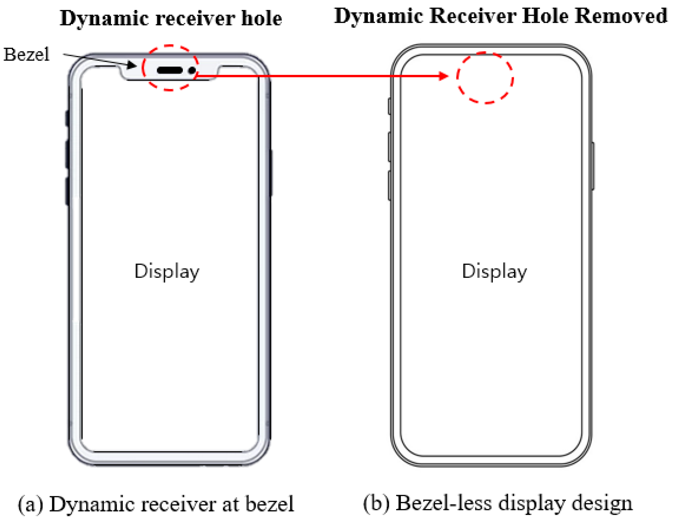
Nowadays, the design trend of the smartphone is shifting toward bezel-less display. Owing to enlarged display, the available space for the dynamic receiver has decreased. The sizes of the holes for dynamic receivers have been reduced, and some parts of the display panels have been either cut or modified to allow for the dynamic receiver holes. However, the dynamic receiver holes are a hindrance to bezel-less display design. The design changes in smartphones are shown in
Figure 1.
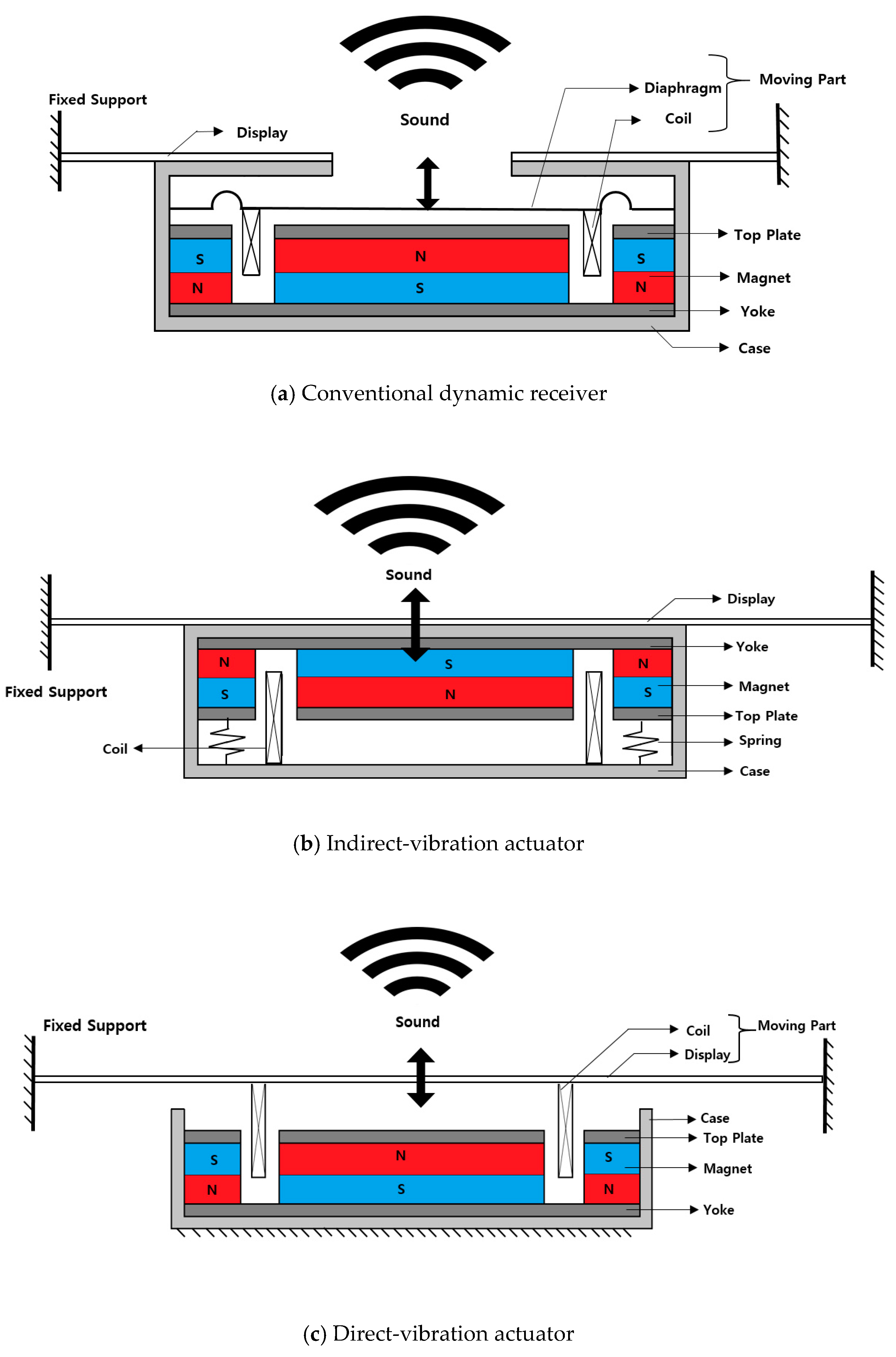
The conventional dynamic receiver generates sound by directly vibrating a diaphragm connected to a moving coil, and the sound is transmitted to a listener through a hole located at the top of the display panel. The simplified structure of the dynamic receiver is shown in
Figure 2a.
Sound can be generated by vibrating elastic objects. In a smartphone, the vibrating display can generate sound that replaces the dynamic receiver. For a bezel-less-display smartphone, indirect-vibration actuators have been introduced and analyzed [
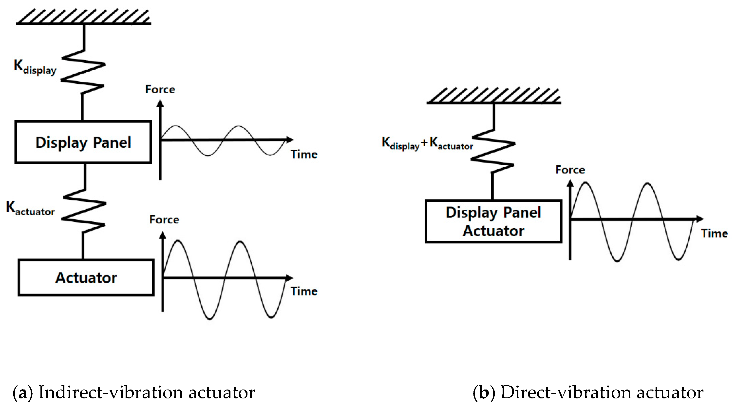
10]. In the indirect-vibration actuator, the oscillating coil is located inside a case. Then, the coil vibrates the case, which transmits vibrations to display panel. The vibrating display generates the sound that the users can hear. The simplified structure of the indirect-vibration actuator and the working principle described using the mass and spring system are shown in
Figure 2b and
Figure 3a, respectively.
Attaching the actuator directly to the display can also generate sound. This is called a direct-vibration actuator. Unlike the indirect-vibration actuator, the direct-vibration actuator’s coil is attached directly underneath the display. The vibrating coil transmits vibrations directly to the display to generate sound. The structure of the direct-vibration actuator and the working principle described using a mass and spring system are shown in
Figure 2c and
Figure 3b, respectively.
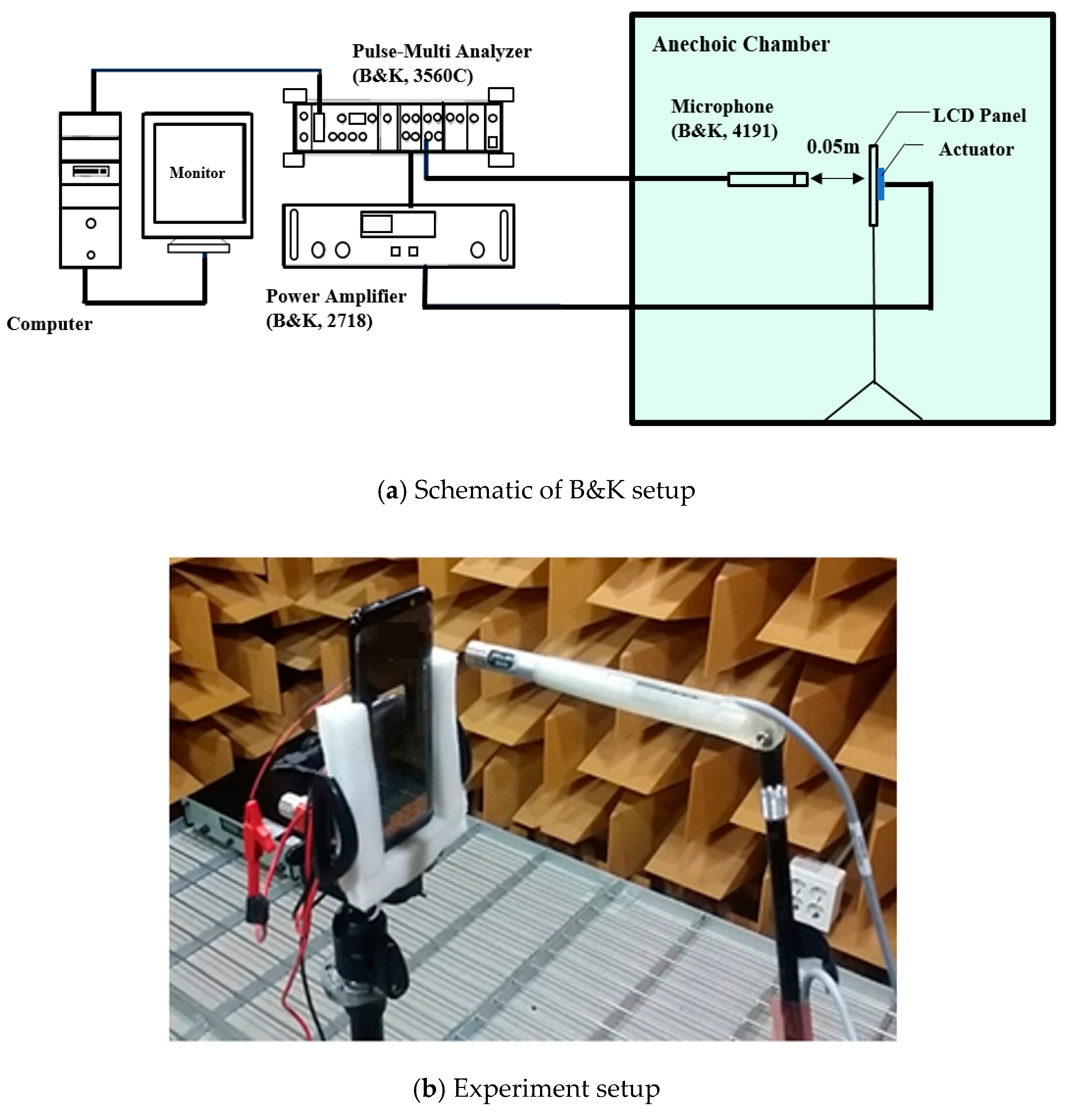
In this paper, the direct-vibration actuator is designed and analyzed. Using sensitivity analysis with force factors, the structure of the direct-vibration actuator is optimized. In the end, an optimized sample is produced, and an experiment is conducted to compare the sound pressure levels (SPLs) between the direct-vibration actuator and dynamic receiver.
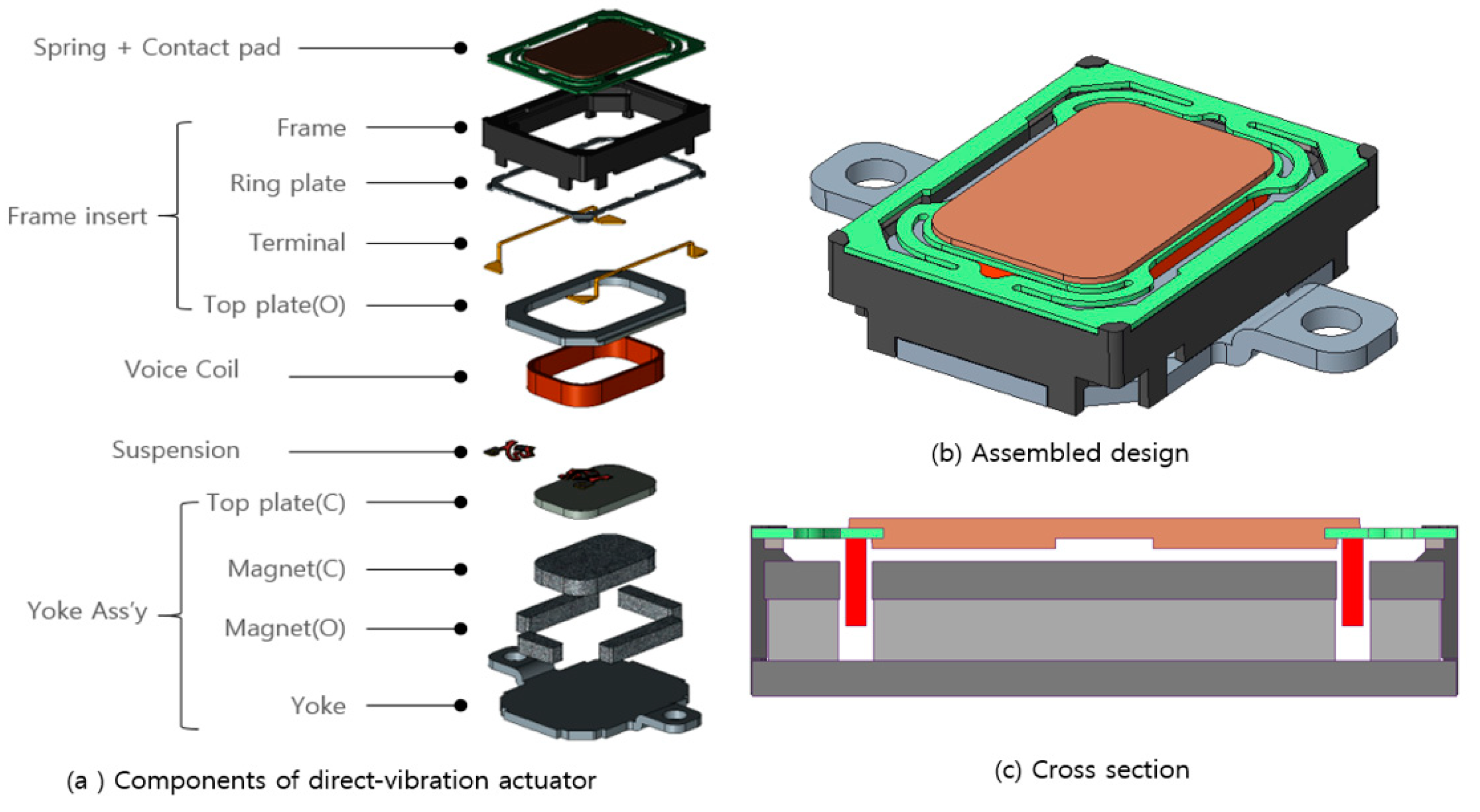
Considering manufacturing assembly, the actuator components are grouped as
Figure 4a. The spring and contact pad is connected directly to the display panel. Under the spring and contact pad, the frame insert is added for the purpose of holding the entire actuator component. The Yoke ass’y consist of center top plate, magnets and yoke which forms a part of electromagnetic circuit. The voice coil is inserted between the center top late and outer top plate with suspensions. After the assembly, the moving voice coil is connected with the spring, suspension and a contact pad where it vibrates the display panel. The assembled design and cross section view is depicted in
Figure 4b,c, respectively. Owing to limited space, the exterior dimensions are limited to 13 × 10.0 × 3.5 mm. The resistance of the coil is 6 Ω with an input power of 1 W.
3. Design Optimization
Since there are many components under the display, the direct-vibration actuator needs to have a maximum electromagnetic force under a limited geometry constraint. The geometry constraint is the maximum size of the actuator. The limited size is 13.0 × 10.0 × 3.5 mm, and the goal is to find the maximum force factor by changing the dimensions of the top plate, yoke, permanent magnet, and coil in the given space. The variations of the flux density and force factor are analyzed by changing two design variables using a sensitivity analysis:
The variation of the force factor on the actuator when changing the thickness of the actuator’s yoke, top plate, and permanent magnet
The variation of the force factor when changing the diameter and number of coil layers.
The effect of current on the force factor is very small due to the small current flow in the coil. The current affects about 0.13% in force factor compared to the result without the current. For this reason, the force factor is calculated without considering the current.
3.1. Thickness Optimization
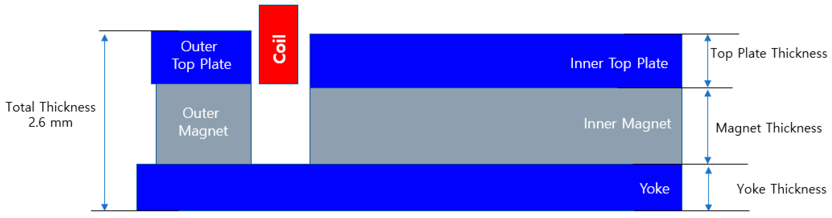
The thicknesses of the top plate, yoke, and permanent magnets directly affect the force factor. The total thickness, including the top plate, yoke, and permanent magnet, should be 2.6 mm. The thickness of each component is briefly shown in
Figure 6.
Increasing the permanent magnet size will strengthen the magnetic field but will decrease the top plate and yoke thickness. A decreased top plate and yoke thickness will cause magnetic flux saturation and thus less magnetic flux to pass through the coil. Consequently, the force factor decreases. Increasing the top plate and yoke thickness will decrease the size of the permanent magnets, which also leads to a decrease in the flux density and force factor.
The thickness of each component is changed to find out the maximum force factor.
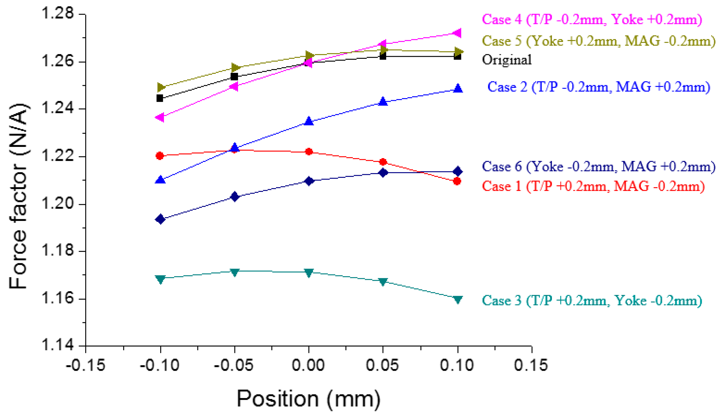
Table 3 shows seven cases for sensitivity analysis and the results when the coil is at a neutral position (0 mm). Considering the limited total height which is 2.6 mm, the changes more than 0.2 mm result in poor force factor. Thus, the optimization is conducted by changing thickness by 0.2 mm.
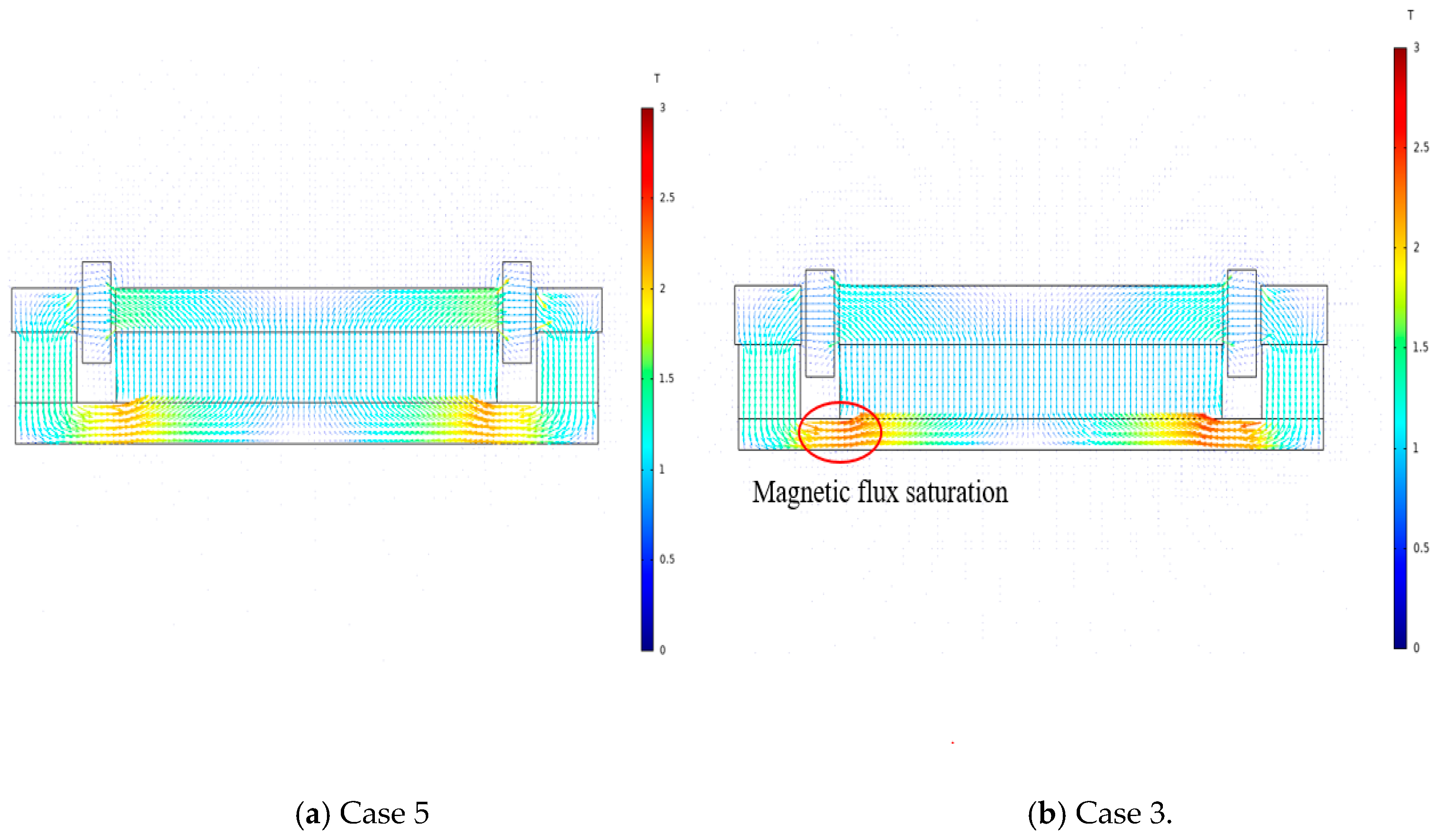
In optimizing the thickness, the changing thickness from −0.2 mm to 0.2 mm shows that the thickness of the yoke greatly affects the force factor. Increasing the size of the magnets lowers the force factor, which means that magnetic flux saturation occurs at the yoke. The magnetic flux flow on Case 5 and Case 3 at the actuator cross section is depicted in
Figure 7. From
Figure 7, the decreased yoke thickness, Case 3, is causing magnetic flux saturation. The force factor in Case 4 varies more than in Case 5 depending on the coil position. The force factor should be consistent in every position. Thus, Case 5 is chosen owing to the higher force factor at every coil position than in the original prototype. The force factor result in every coil position is shown in
Figure 8.
3.2. Coil Optimization
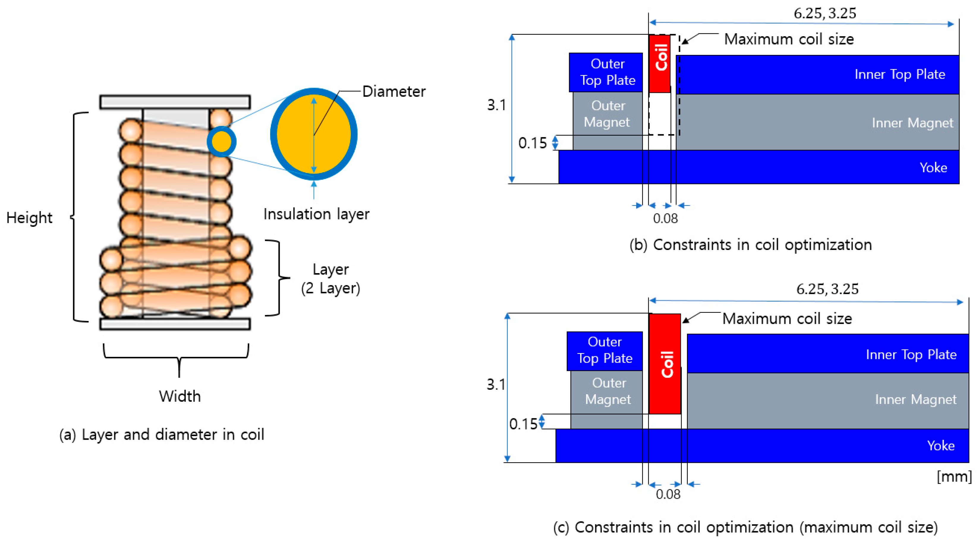
The variation in the force factor caused by the change of layers and the diameter of the coil is analyzed. The coil resistance is fixed at 6 Ω. The layer is the number of coil windings for each width. The diameter of the coil refers to the diameter of copper wire through which the current flows, excluding the insulation layer thickness.
While maintaining the same resistance and layer, decreasing the diameter can decrease the force factor since the resistance per unit length increases, which leads to a decrease in the total coil height. The decreased coil height may cause less magnetic flux to pass through the coil. Similarly, while maintaining the same resistance and diameter, increasing the number of layers decreases the coil height and may decrease the force factor.
With regard to the geometry constraint in the coil optimization, the distance from the yoke to the top of the coil is maintained at 3.1 mm when the top of the coil is in a fixed position. The exterior coil surface must be positioned at 6.25 mm (longitudinally) and 3.25 mm (laterally), respectively, from the center of the top plate.
The distance from the coil bottom to the yoke should be at least 0.15 mm. The air gap between the coil and the top plate is fixed at 0.08 mm. While maintaining the coil resistance at 6 Ω, a diameter from 0.05 mm to 0.15 mm is used, and 4, 6, 8, and 10 layers are chosen to determine the maximum force factor. The reason for choosing an even-numbered layer is that from the manufacturing process, the input wire and output wire should start and end in the same position. To maximize the force factor, it is important to find the best combination between the diameter and the total coil length. The constraints and descriptions for coil optimization are briefly shown in
Figure 9.
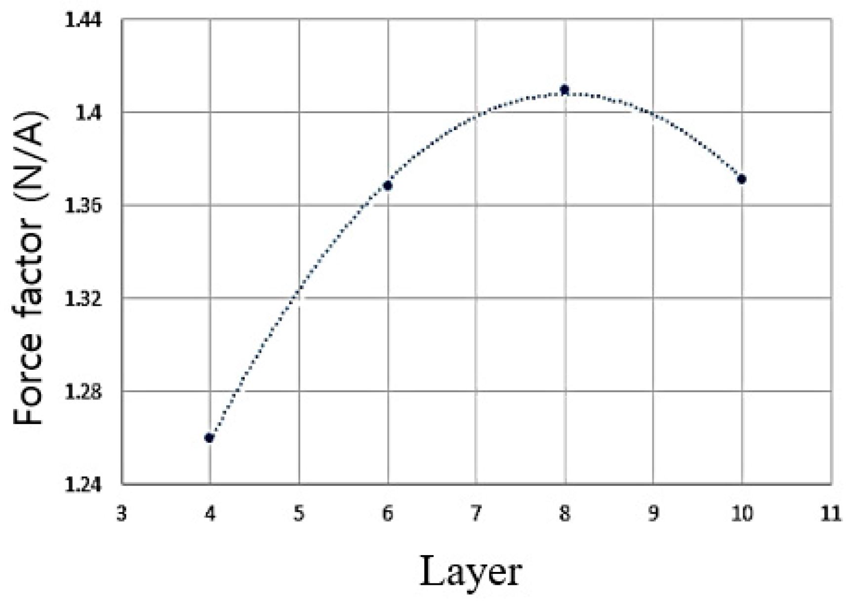
Table 4 lists the specifications of four cases that have the maximum force factor on the dedicated coil diameter.
The eight-layer coil with a diameter of 0.11 mm is found to have the maximum force factor. The maximum force factor in 4, 6, 8, 10 layers in a neutral position is shown in
Figure 10.
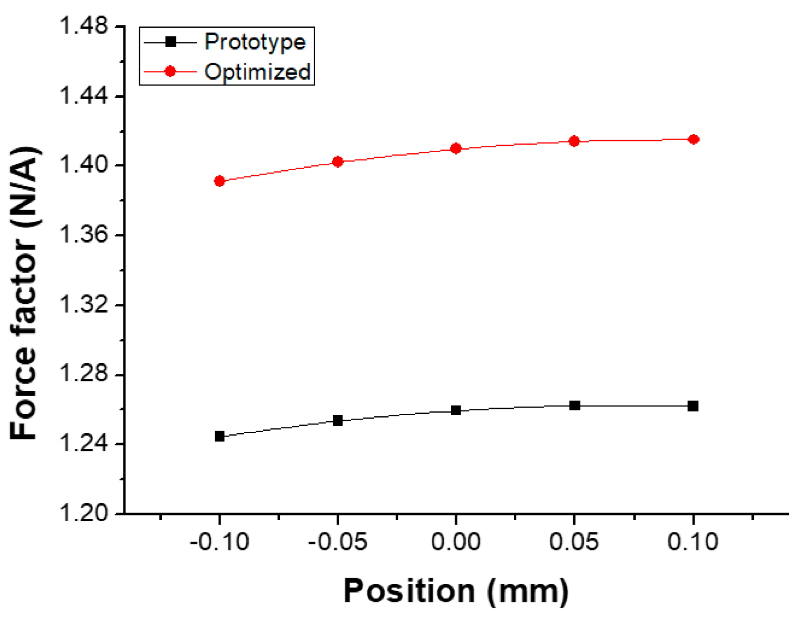
By combining all results, the final optimized force factor is obtained, which is shown in
Figure 11. The optimized model has a 12% higher force factor than the original prototype.
5. Conclusions
Smartphones have become the core technology for many industries. The main design trend is to maximize the display size while maintaining portability. To achieve the bezel-less display design, a new actuator to replace the conventional dynamic receiver is needed. The indirect-vibration actuator was developed for a bezel-less display design to generate sound by vibrating the entire display. Instead of using an indirect-vibration actuator, this paper suggests a new structure that generates sound by vibrating the display panel directly. The new structure is called the direct-vibration actuator.
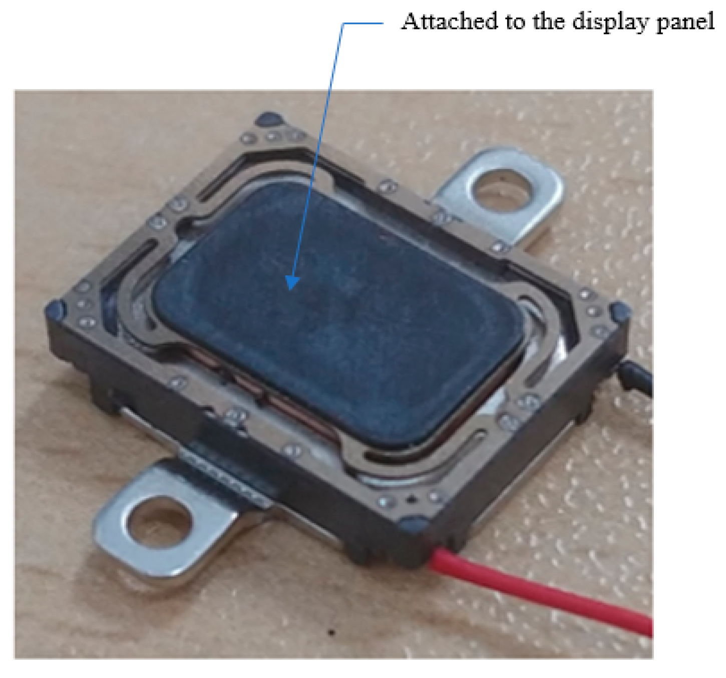
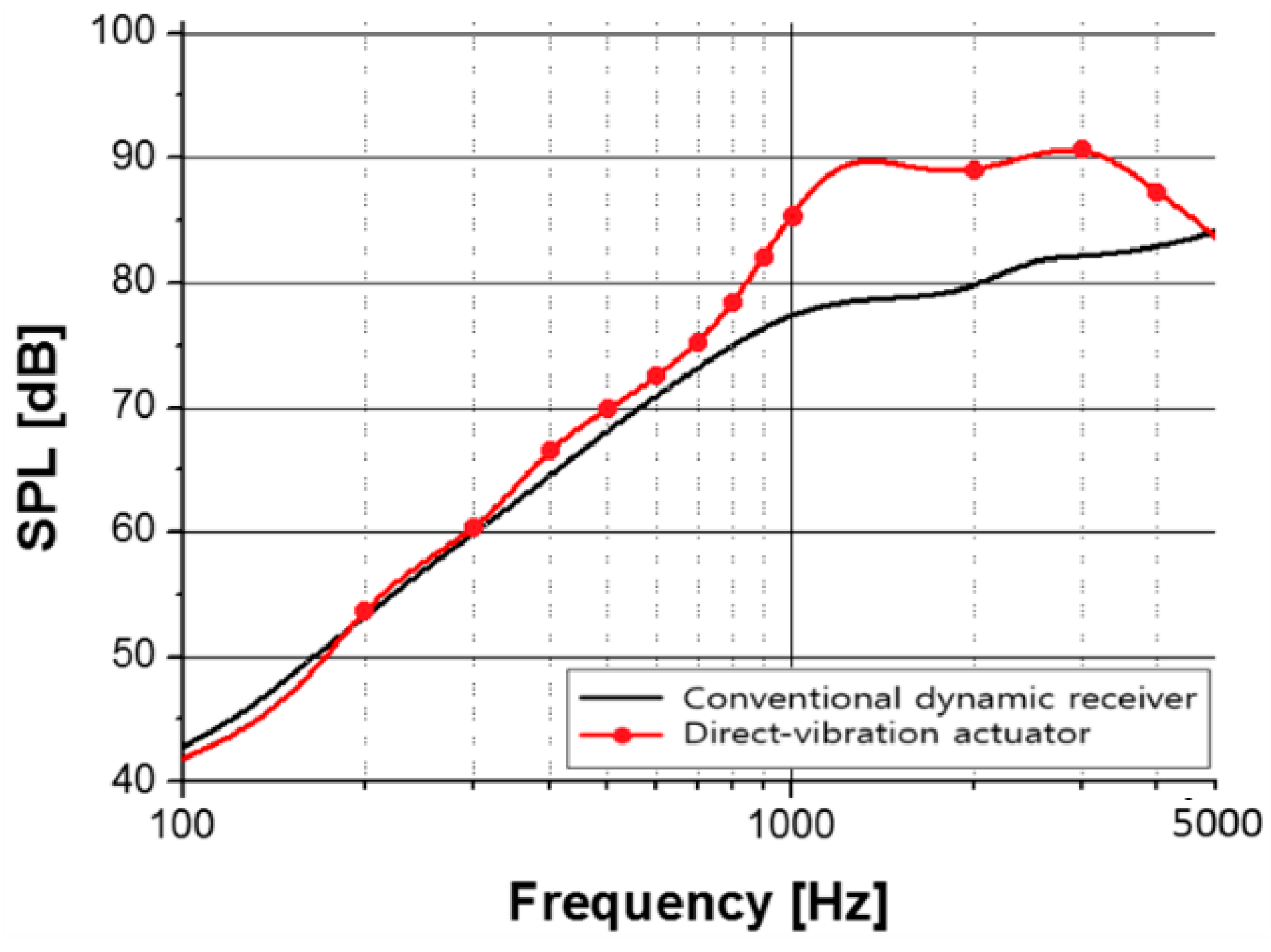
By calculating the force factor via the 3D finite element method, the design was optimized. First, the thickness of the magnetic circuit component was analyzed to maximize the force factor. Then, the coil was optimized. As an optimization result, the force factor increased by about 12% compared to the original actuator. A sample was manufactured, and the SPL was compared to the dynamic receiver. The experiment result showed that the direct-vibration actuator can substitute for the dynamic receiver. This allows for bezel-less display designs on mobile devices.


