Abstract
Two retrofit strategies, aiming at increasing the collapse resistance of simple connections by adding seat angles and steel plates with long-slotted holes, are proposed in order to address the vulnerability of steel gravity frames under column loss scenarios. A high-fidelity, detailed, finite element model for a planar composite frame is developed and calibrated against experimental data and is used to conduct numerical analysis to explore the effectiveness of the proposed retrofit strategies. The simulation results show that the planar composite frame with enhanced connections exhibits significantly higher collapse resistance and better ductility under column loss scenarios compared with the one with conventional connections. Meanwhile, it is also revealed that the proposed retrofit strategies have an insignificant impact on the behavior of the structural system under earthquakes. These two retrofit strategies are then implemented to retrofit the gravity system of a 10-story, seismically designed steel frame structure, which has been shown to be vulnerable to progressive collapse after an interior gravity column is forcibly removed or impacted by a heavy vehicle with high speed. Numerical simulations were performed using a 3-D micro-based model and the simulation results illustrate that progressive collapse of the structure with enhanced gravity systems is prevented under both scenarios. Therefore, the proposed retrofit strategies are effective in preventing the progressive collapse of existing steel structures employing simple connections.
1. Introduction
Progressive building collapse, which is defined as “the spread of an initial local failure from element to element, resulting eventually in the collapse of an entire structure or a disproportionately large part of it” in ASCE 7-16 [1], can be triggered by man-made and natural hazards, such as blast, vehicle and aircraft impact, fire, and major earthquakes. Although the probability of such catastrophic events is low, the impact is extreme when they do occur. There are a number of examples in history in which structural failures and collapse of buildings resulted in huge economic damage and extensive loss of human lives, such as the partial collapse of Alfred P. Murrah federal building in Oklahoma City in 1995 and the collapse of the twin towers of the World Trade Center in New York City in the terrorist attack on September 11th, 2001.
Extensive experimental and numerical studies have been performed to investigate the collapse response of civil structures. Experimental studies on progressive collapse used to be quite rare in the literature because of the expense and difficulty of experimentation. This trend has been reversed thanks to the boomed experimental tests conducted to investigate progressive collapse behavior in recent years, including Yang and Tan [2], Yang and Tan [3], Fu et al. [4], Li et al. [5], Liu et al. [6], Ren et al. [7], Shan et al. [8], Wang et al. [9], Yang et al. [10], Kang and Tan [11], Li et al. [12], Lu et al. [13], Peng et al. [14], Qian and Li [15], Zhong et al. [16], Jiang et al. [17], Lu et al. [18], Ma et al. [19], Qian and Li [20], Han et al. [21], and Shan et al. [22]. These tests provide a great number of high-quality experimental results that can be used for computational model validation, which in turn promotes the development of computational models for progressive collapse. Research efforts pertaining to numerical analysis of progressive collapse in recent years can be found in Li and El-Tawil [23], Alogla et al. [24], Gerasimidis and Sideri [25], Arshian and Morgenthal [26], Brunesi and Parisi [27], Ding et al. [28], Feng et al. [29], Jiang and Li [30], Pham et al. [31], Pham et al. [32], Gernay and Gamba [33], Li et al. [34], Yu et al. [35], Stephen et al. [36], and Eren et al. [37].
The ultimate goal of all the studies related to progressive collapse is to protect building structures from collapsing under abnormal loading conditions and thus avoiding massive casualties and economic loss. Crawford et al. [38] presented retrofit methods suitable for mitigating progressive collapse for both steel frame and reinforced concrete buildings. Approaches that can increase the collapse resistance of concrete structures were proposed by Orton et al. [39], Kim and Shin [40], Qian and Li [41], Schachter and Smilowitz [42], Liu et al. [43], Al-Salloum et al. [44], Qian et al. [45], Qian and Li [46], and Vieira et al. [47]. However, quite a few research efforts have been dedicated to the development of strategies which are capable of improving the robustness of both newly designed steel buildings and existing steel buildings, examples of which can be found in Liu [48], Rezvani et al. [49], Ghorbanzadeh et al. [50], and Naji and Ommetalab [51].
As one of the most common steel connections, simple connections allow relative rotation of the connected members and thus can only transfer shear forces. Therefore, they are designed to resist vertical gravity loads and are used in the steel frame structures of non-seismic areas and in the gravity frames of seismically designed frames in the US and Europe. Comparing with moment connections and semi-rigid connections, such as those designed using the method proposed by Sánchez-Olivares and Espín [52], the simple connections have weaker strengths. It has been revealed by the author in previous research ([53]) through nonlinear dynamic analysis using validated three-dimensional numerical models that progressive collapse of seismically designed steel-framed structures is precipitated once an interior column belongs to a gravity system, which is connected to the adjacent beams using simple connections, is suddenly removed because the simple connections are too weak to develop adequate catenary action. Although Liu [48] and Ghorbanzadeh et al. [50] proposed retrofitting schemes for simple connections against progressive collapse, these approaches either influence the seismic behavior of the structural system by increasing the lateral stiffness or are too complicated to be implemented in practice. Additionally, the effectiveness of these approaches in the mitigation of progressive collapse of composite frames was not shown because the effects of slabs were not accounted for. Therefore, it is of great importance to develop simple, economical, and easy-to-implement rehabilitation strategies that are capable of improving the collapse resistance of composite frames with simple connections effectively, in order to prevent progressive collapse of existing steel frame buildings.
In this study, two retrofitting strategies against progressive collapse of existing steel gravity frames through enhancing the tensile strength of simple beam-to-column connections are proposed. The effectiveness of the proposed strategies for improving the collapse resistance of planar composite frames with simple beam-to-column connections is evaluated using high-fidelity continuum finite element models which are sophisticatedly calibrated against experimental data. Additionally, the proposed strategies are utilized to strengthen the simple connections in the gravity system of a high-rise seismically designed steel structure. The dynamic behavior of the retrofitted structure subjected to sudden loss and vehicle impact of an interior gravity column is also explored using a 3-D micro-based computational model.
2. Numerical Models for Composite Frames with Simple Connections
2.1. Modeling Approach
A planar composite frame tested by Yang et al. [10] to investigate its behavior under column loss scenario is used. The structural layout and member sizes are shown in Figure 1a. Web cleat connections, which fall into the category of simple connections, are employed by the composite frame to connect the steel beams to the columns. The details of the connections are provided in Figure 1b. More details of the prototype structure can be found in Yang et al. [10].
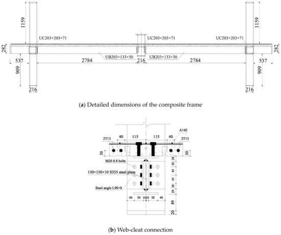
Figure 1.
Test specimen in Yang et al. [10] (unit: mm).
A physical-based, high-fidelity, detailed finite element model is developed for the planar composite frame, as shown in Figure 2a. The general modeling approach adopted herein is to model all structural elements, including composite slab, beams, columns, and connections between them. This model is composed of approximately 250,000 continuum finite elements. Since the focus of the study is on nonlinear response, each element’s representation permits inelastic response to occur including fracture and separation, where appropriate. To enable realistic simulations of collapse, interpenetration between the various components of the model is prohibited. The elements in all steel components can be eroded once a prespecified failure strain is reached to mimic fracture of the steel. The parameters of the constitutive models representing the stress–strain responses of these structural components are all obtained on the basis of the test results in Yang et al. [10]. All simulations are performed using the explicit finite element code LS-DYNA. In order to save some computational cost, time scaling is performed and the prescribed minimum time step is 5 × 10⁻⁷s.
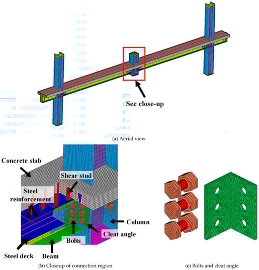
Figure 2.
Details of the finite element model M0.
The composite slab is composed of steel deck, concrete slab, steel mesh, rebars, and shear studs. As shown in Figure 2b, the concrete is modeled using 8-node brick elements. The inelastic behavior of concrete is represented using a cap model with a smooth intersection between the shear yield surface and hardening cap [53] with a compressive strength of 26 MPa. The steel mesh and rebars in the slab are modeled using truss elements, whose stress–strain responses are represented using J2 plasticity models with kinematic hardening. The reinforcements are assumed to be fully bonded to the concrete slab. The yield strength of the steel reinforcements is 615 MPa, and the failure strain is assumed to be 0.12. The steel deck is modeled using fully integrated four-node isotropic shell elements and is assumed to have a bilinear stress–strain relationship with a yield strength of 647 MPa and failure strain of 0.12. The nodes of the steel deck elements and the concrete deck elements are not merged, and therefore they can separate from each other if needed. However, the friction between the steel deck and concrete slab is taken into account. The shear studs, which are used to connect the composite slab and the underlying steel beams, are also modeled using fully integrated solid elements (Figure 2a), which are embedded in the concrete slab and fully bonded to the concrete elements. An equivalent rectangular cross-section, the area of which is determined to achieve identical shear strength of the original shear studs with a circular cross-section, is adopted in order to reduce the complexity of modeling and a J2 plasticity model is used to represent their inelastic responses.
As illustrated by Figure 2b,c, the beams, columns, and the web cleat connections, which are comprised of angles and bolts, are all modeled using fully integrated eight-node isoparametric solid elements, and their inelastic responses are all represented by J2 plasticity models. The mesh is refined in the vicinity of the connection, which ranges in size between 3 to 5 mm, in order to ensure that the large strain and stress gradient in such regions are captured correctly. Ductile fracture is assumed to occur to beams and columns when the plastic strains reach 0.55 and 0.60, respectively. The steel angles have a yield strength of 320 MPa and are assumed to fracture when their strain achieves 0.50. The yield strength of the bolts is 613 MPa, and the tensile failure criterion for bolts elements is taken to be a plastic strain of 0.70 after calibrating against the results of the experimental tests conducted by Yang and Tan (2013a).
2.2. Validation Studies
The proposed modeling approach is validated by comparing the responses of the computational models with disparate experimental data.
2.2.1. Bolted-Angle Connections Test
The simple connections resist progressive collapse through catenary action, and therefore the collapse robustness of the gravity frames relies largely on the tensile behavior of the simple connections. Yang and Tan [2] tested 14 bolted-angle connections under tension in order to address this issue. Each specimen comprised 4 angles and a number of bolts (12 for Type A specimens and 18 for Type B and C specimens). The angles were connected by the bolts through thick steel plates, which were not allowed to fail since focus was placed on the behavior of angles and bolts. The thick plates in the vertical direction were also used as loading plates, which were clamped to the testing machine and to which a monotonic tensile force was applied.
Specimen A90-8-50-I, in which web cleat connections were considered, was selected for validation study because all the parameters which may have a significant impact on the tensile behavior of the web cleat connections in A90-8-50-I and the prototype structure were identical, including the size of the angles (L90 × 8) and bolts (Grade 8.8 M20) and the distance between the centerlines of horizontal bolts and the vertical loading plates (50 mm). The yield and ultimate strengths of the angles were 323 MPa and 473 MPa, respectively. A numerical model of specimen A90-8-50-I was developed using the proposed modeling approach, as shown in Figure 3b, and the same loading scheme and boundary condition with the experimental test were adopted when performing the simulation. The comparisons between the experimental and simulation results, including the load–displacement curves and failure modes, are shown in Figure 4. As shown in Figure 4a, the model yields good overall load-versus-deflection responses, managing to capture the initial slopes, hardening attributable to catenary action, peak loads, and deformations at failure. Furthermore, Figure 4b reveals that the proposed model also captures the observed failure mode well, including the deflections and fracture of the angles. Therefore, the proposed model is able to represent the behaviors of the web cleat connections subjected to monotonic tensile force well.
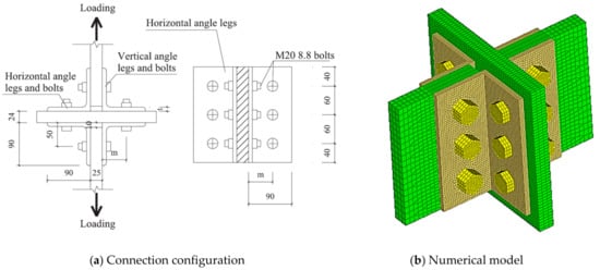
Figure 3.
Numerical models of bolted-angle connection A90-8-50-I in Yang and Tan [2].
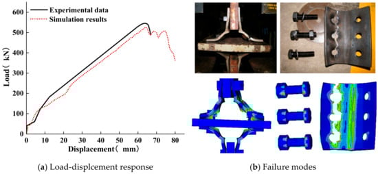
Figure 4.
Comparison between simulation and experimental results of A90-8-50-I under tension.
2.2.2. Beam-to-Column Sub-Assemblage Test
Yang and Tan [3] conducted experimental tests on 9 beam-column assemblies of beam–joint–beam pattern under a center column removal scenario. The failure modes, collapse-resisting mechanisms, and deflections of the specimens were investigated. Each test specimen was composed of two half-span beams and a center column. The cross-section dimensions of the beams and columns were UB 254 × 146 × 37 and UC 203 × 203 × 71, respectively. Three types of bolted-angle beam-to-column connections, including web cleat, top and seat angle, and top and seat with web angle, were considered in their study. The test setup is shown in Figure 3a. The beam ends are pinned to simulate the constraints from the surrounding structural elements. The central column was pushed down vertically in displacement control at a rate of 6mm/min.
Among all of the 9 specimens, specimen W-8 employed web cleat beam-to-column connections consisting of L90 × 8 and Grade 8.8 M20 bolts, which were also used by the prototype composite frame. According to the coupon test results, the yield and ultimate strengths of the angles were 331 MPa and 484 MPa, respectively, which were close to those of specimen A90-8-50-I discussed in the last section. Therefore, for the purpose of validation, a finite element model of W-8 was built in the manner previously described, as shown in Figure 5b,c. A discrete beam element, whose force-displacement response was obtained on the basis of the experimental results, was used to represent the constraints provided by the test setup system to beam ends. As shown in Figure 6a, a good match between the load-deflection response obtained from the computational and experimental results is achieved, especially under large deformation conditions, when catenary action develops quickly. The peak load and deformation at failure are both well represented (within 3%). Figure 6b shows the comparison between the failure mode observed at the end of the test and captured by the simulation. The model manages to simulate the failures reasonably well, such as fracture of the angles and plastic deformation of the bolts.
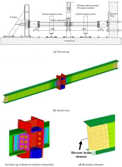
Figure 5.
Numerical models of the sub-assemblage (W-10) in Yang and Tan [3].
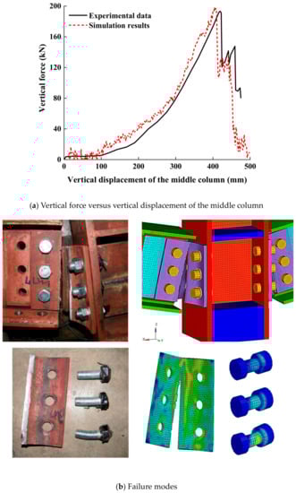
Figure 6.
Comparison between simulation and experimental results of W-10 subjected to loss of a middle column.
2.2.3. Composite Frame Test
Yang et al. [10] conducted experimental studies on the robustness of planar composite frames, in which four specimens were tested under an internal column loss scenario. Each specimen consisted of two beam spans and three columns. The cross-section dimensions of the beams and columns were UB203 × 133 × 30 and UC203 × 203 × 71, respectively. Two types of beam-to-column connections were considered, namely web cleat connection and flush end plate connection. The former is a simple connection, and the latter can be categorized as a semi-rigid connection. The test setup is shown in Figure 7. A concentrated load was applied to the middle column, whose out-of-plane movement was prevented by pushing it down vertically. Since the inflection point locates as the middle of the column, only half of the length of the exterior columns was considered. The two exterior columns were connected to the foundation using hinged supports, and constant compressive loads were applied to their tops to simulate the forces transferred from the upper floors. Furthermore, the tops of the exterior columns and the ends of extended beams were all pinned so that their lateral movement was constrained.
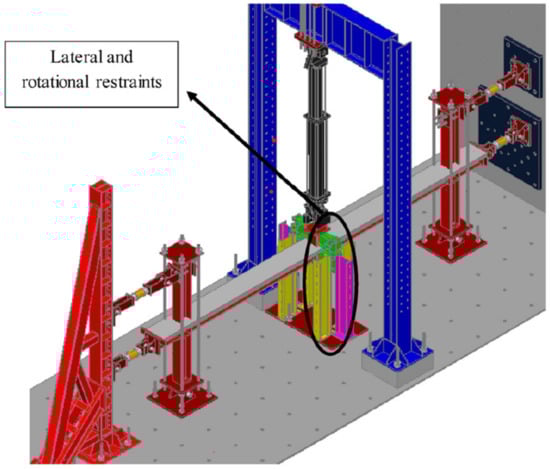
Figure 7.
Test setup rigs of composite frame tests conducted by Yang et al. [10].
One of the four specimens was selected as the prototype structure used in this section, i.e., specimen I-W-MT. As mentioned earlier, the beams and columns of the specimen were connected by web cleat connections, comprised of L90×8 angles and Grade 8.8 M20 bolts. The yield and ultimate strengths of the angles were 316 MPa and 446 MPa, respectively. The composite slab consisted of concrete slab, A142 (6 mm) steel mesh, 4 T13 steel bars, and steel deck. The tensile and compressive strengths of concrete were 2.18 MPa and 25.95 MPa, respectively. The yield and ultimate strengths of steel were 450 MPa and 527 MPa, respectively, the steel deck’s corresponding properties were 647 MPa and 667 MPa, and the steel rebar’s corresponding properties were 615 MPa and 705 MPa.
As shown in Figure 8, the actual boundary condition induced by the test setup rigs was represented by a series of discrete beam elements. Figure 9 shows the comparison between the simulation results and experimental data. As shown in Figure 9a, the numerical model is able to reasonably match the measured experimental data in terms of initial stiffness, peak load, and displacement at failure. Moreover, the model also successfully represents the development of the axial forces in the beams, as shown in Figure 9b, indicating that the catenary action can be accurately accounted for by the proposed computational model. As shown in Figure 9c, the proposed model also captures the failure modes well, including concrete crushing and fracture of angles.
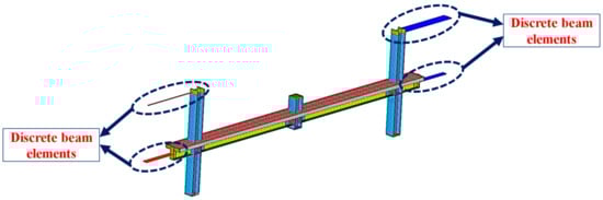
Figure 8.
Boundary constraints of the composite frame model.
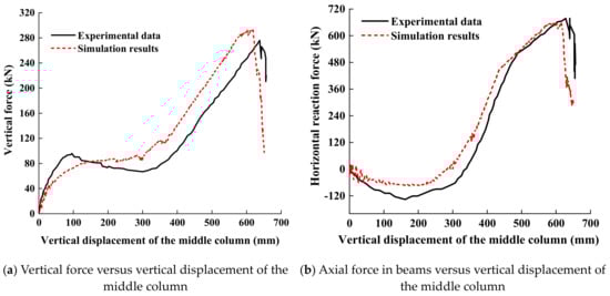
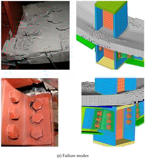
Figure 9.
Comparison between simulation and experimental results of I-W-MT in Yang el al. [10].
2.3. Simulation Setup
The validation studies support the accuracy and suitability of the proposed models to represent the collapse response of composite frames with simple beam-to-column connections. In the following discussions, the proposed model is modified in a manner as described in Figure 10, and the modified model is designated as M0. In model M0, the full length of the exterior columns is used with all column ends fixed, which is an equivalent boundary condition with the ones adopted in the composite frame test (Yang et al. [10]). Figure 11 illustrates the comparison between the load–displacement curves computed using the numerical model with and without considering the discrete elements connected to the ends of the extension beam, and no evident difference can be observed. Therefore, the constraints provided by these discrete elements in the axial direction of the beams have a limited impact on the collapse resistance of the composite frame and are dismissed in model M0. As in the test, the middle column of model M0 is pushed down vertically in displacement control until failure occurs.
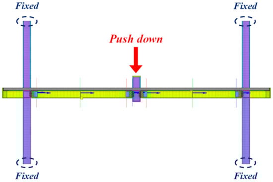
Figure 10.
Simulation setup.
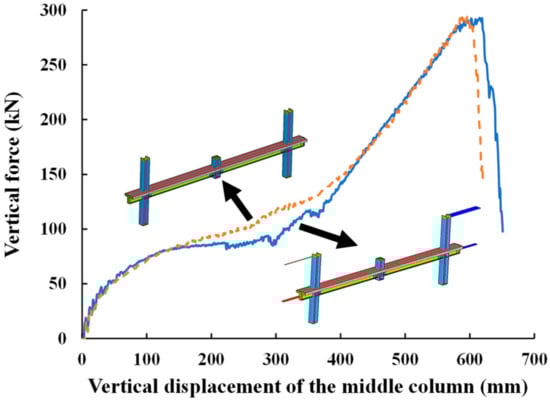
Figure 11.
Comparison between the load–displacement curves obtained by the models with and without discrete elements connected the ends of the beams.
3. Proposed Retrofit Strategies
3.1. General Retrofit Approach
In order to propose practical retrofit strategies against progressive collapse of composite frames with simple connections, their collapse resistance mechanisms need to be figured out. Generally speaking, the collapse resistance of a composite frame is attributed to two mechanisms: (1) flexural action formed by composite effects between composite floor system and the underlying steel beams; and (2) flexural action formed by the tensile force developed in the steel beams and steel deck and reinforcement in the composite slab system, and the development of these mechanisms depends largely on the types of beam-to-column connections.
The contributions of the flexural action and catenary action to the total collapse resistance of the composite frame are depicted in Figure 12 and are quantified by calculating the vertical component of the shear force and axial force in arbitrary cross section of the composite beam using the simulation results of model M0. As shown in Figure 12, when the vertical displacement of the middle column was less than 260 mm, the flexural action was the only source of the collapse resistance. After that, the catenary action was initiated, and as the increase of the vertical displacement the middle column, the catenary action ramped up quickly. When the vertical displacement of the middle column reached around 430 mm, the contribution of the catenary action to the collapse resistance surpassed that of the flexural action and the catenary action became the predominant collapse resistance mechanism. Before the occurrence of the failures of the web cleat connections, 95.8% of the total collapse resistance was from the catenary action, which was also the final mechanism that contributes to the collapse resistance. The results indicate that the robustness of steel gravity frames depends on the catenary action.
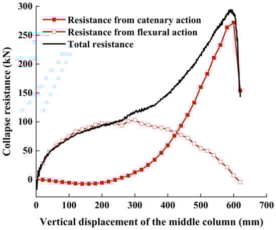
Figure 12.
Collapse resistance of the composite frame.
The retrofit strategies proposed in this study aim at improving the collapse resistance of gravity frames through enhancing the tensile strength of the simple beam-to-column connections. On the other hand, in order to minimize the variation of seismic behavior of the structural, it is undesirable to increase the flexural stiffness of the composite connections significantly.
3.2. Retrofit Strategy 1: Addition of Bolted Seat Angle
In this retrofit scheme, a simple beam-to-column connection is strengthened by using an L90 seat angle with a length of 150 mm, whose legs are connected to column flange and beam flange using two Grade 8.8 M20 bolts, respectively, as shown in Figure 13. Seat angles with thicknesses of 8 mm, 10 mm, and 12 mm are considered.
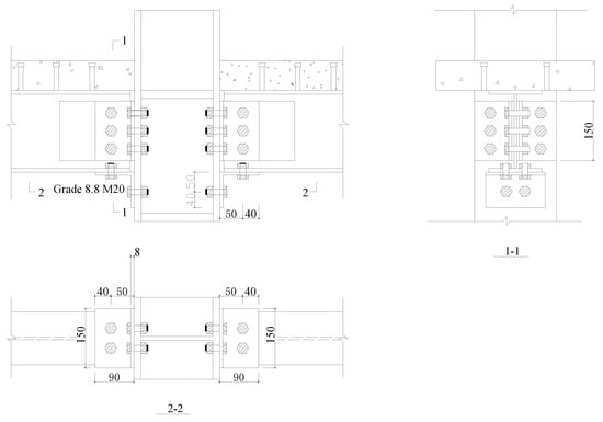
Figure 13.
Retrofit strategy 1 (unit: mm).
To investigate the effectiveness of retrofit strategy 1 in increasing the collapse resistance of the planar composite frames with simple connections, a series of static and dynamic push-down analysis was conducted using model M0 and M0 -RS1-X, where RS1 denotes the adoption of retrofit strategy 1 and X represents the thickness of the seat angles. For example, M0-RS1-8 represents 8 mm thick seat angles, which are used to strengthen the simple connections. The additional seat angles and bolts, which were used to strengthen the simple connections, were modeled using the same modeling approach with M0. A closeup of the beam-to-column connection region of the model is shown in Figure 14. The static and dynamic responses of M0-RS1-8, M0-RS1-10, M0-RS1-12, and unenhanced model M0 are compared in Figure 15a,b, respectively.
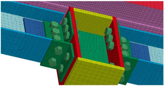
Figure 14.
Model M0-RS1: connection region.
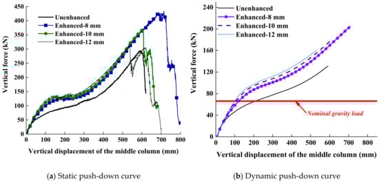
Figure 15.
Comparison between the unenhanced and enhanced composite frame using retrofit strategy 1.
Based on the static push-down analysis results, which are illustrated by Figure 15a, the static ultimate collapse resistances () of M0-RS1-8, M0-RS1-10, and M0-RS1-12 reached 434 kN, 371 kN, and 310 kN, respectively, which were 47.6%, 26.2%, and 5.4% larger compared with that of M0. Additionally, the ultimate failure deformation of the composite frame, , which is defined as the vertical displacement of the middle column when fracture occurs to the connections/retrofitted connections, was also increased by 20.8% and 2.3%, respectively, in models M0-RS1-8 and M0-RS1-10. However, compared with the unenhanced composite frame, the ultimate failure deformation of M0-RS1-12 decreased by 10.2%. As the increase of the thickness of the seat angles, the efficiency of retrofit strategy 1 decreased, although differences in responses of M0-RS1-8, M0-RS1-10, and M0-RS1-12 were only observed in the final stages of collapse. This was due to the differences between the failure modes of the additional bolted angle with various thicknesses, as shown in Figure 16. Under large deformation conditions, the seat angles underwent plastic deformation shown in Figure 16 due to the extension of the retrofitted connections to form additional catenary action. When thicker seat angles (10 mm and 12 mm) were used, the bolts connecting the seat angle and column flange were subjected to the combination of excessively large shear force and tensile force, as shown in Figure 16a, and eventually, these bolts lost their loading carrying capacities. However, Figure 16b demonstrates that the bolts at the same location were mainly under tension throughout the loading process because the seat angles with smaller thicknesses (8 mm) transferred less amount of shear force to them and thus the seat angles would be torn up before failures of bolts. The additional bolted seat angles with smaller thickness failed in a more ductile manner compared with those with larger thickness and therefore were capable of providing a larger amount of additional catenary action. Under a sudden column loss scenario, similar trends were observed, according to Figure 15b. The dynamic ultimate collapse resistance can be increased by 55.7%, 35.9%, and 22.1% after the simple connections were strengthened by adding seat angles with a thickness of 8 mm, 10 mm, and 12 mm, respectively, and the maximum dynamic vertical displacement of the middle column under nominal gravity loads could be reduced by more than 40%.
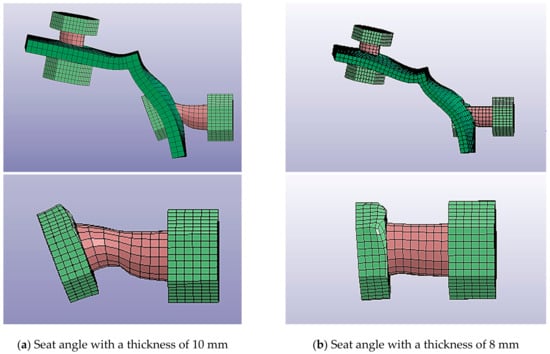
Figure 16.
Failure modes of the bolted seat angles.
The collapse resistance mechanisms of the retrofitted composite frames were analyzed. As an example, the contributions of catenary action and flexural action to the total collapse resistance of M0-RS1-8 are presented and compared with those of M0 in Figure 17. Although more flexural action was developed in M0-RS1-8 than in M0, the discrepancy was limited. The maximum values of collapse resistance due to flexural action in M0-RS1-8 and M0 were 64 kN and 53 kN, respectively, indicating that the flexural stiffness of the connections was not significantly increased by the employment of retrofit strategy 1. On the other hand, the collapse resistance due to catenary action before failure increased from 136 kN to 177 kN (a more than 30% increase). Similar trends were observed in M0-RS1-10 and M0-RS1-12.
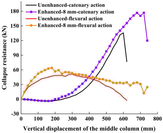
Figure 17.
Collapse resistance mechanisms of model M-SC1-8.
In summary, the robustness of the structural system can be improved substantially by using retrofitting scheme 1 without evident change in flexural stiffness of the connections, and for the given configuration, the optimal thickness of seat angles is 8 mm.
3.3. Retrofit Strategy 2: Addition of Steel Plates with Long-Slotted Holes
In this retrofitting scheme, a simple beam-to-column connection in the steel gravity frame is enhanced by using a steel plate with two long-slotted holes, which is welded to the column flange and bolted to the beam flange using Grade 8.8 M20 bolts, as shown in Figure 18. The steel plate is 120 mm long, 100 mm wide, and 8 mm thick so that the tensile strength of the plate, bearing strength of the plate at slotted holes, and the shear strength of the bolts are close to each other and the constructional materials can be fully utilized. After loss of the middle column, the bolts can slide through the long slots initially, which is supposed to have minor impact on the collapse resistance of the retrofitted connection. However, as the increase of deformation, the bolts will be in contact with the steel plates eventually and thus additional catenary action can be developed.
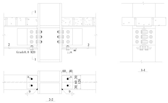
Figure 18.
Retrofit strategy 2 (unit: mm).
The closeup at the connection regions of the numerical model representing the retrofitted composite frame using retrofit strategy 2 is shown in Figure 19, in which the bolts and steel plates were modeled using solid elements. Three different allowable sliding distances of the bolts through the long slots a (Figure 18) were considered: 12 mm, 24 mm, and 36 mm, and the corresponding variants of numerical models were termed M0-RS2-a12, M0-RS2-a24, and M0-RS2-a36. The load–displacement curves obtained through static and dynamic pushdown analysis using M0-RS2-X series and M0 are shown in Figure 20a,b, respectively. Clearly, the collapse resistance of the composite frame could be increased substantially after the simple connections were strengthened using retrofit strategy 2 under both static loading conditions and sudden column loss scenarios. When the middle column was pushed down quasi-statically, the static ultimate collapse resistance of the planar gravity frame was increased by 20.7%, 37.5%, and 40.1% after attaching the steel plates with 12 mm, 24 mm, and 36 mm, and the ultimate displacements, , of M0-RS2-a12, M0-RS2-a24, and M0-RS2-a36 were 1.05, 1.19, and 1.17 times of that of M0. After the center column was suddenly removed, the dynamic ultimate collapse resistance, , of models M0-RS2-a12, M0-RS2-a24, and M0-RS2-a36 were 31.3%, 45.8%, and 38.9% compared with that of M0, and the peak dynamic displacement under nominal gravity load was around 25% smaller comparing that of M0.
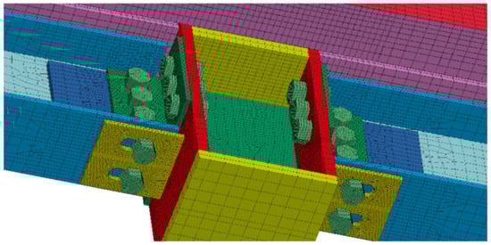
Figure 19.
Model M0-RS2: connection region.
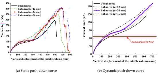
Figure 20.
Comparison between the unenhanced and enhanced composite frame using retrofit strategy 2.
The sources of resistance that contribute to structural robustness, namely catenary action and flexural action, of M0-RS2s were quantitively studied. Generally speaking, the variation laws of catenary action and flexural action of the retrofitted frames with different lengths of long slots pertaining to vertical displacement of the middle column were similar. For example, the development of collapse resistance mechanisms of M0-RS2-a24 and M0 are illustrated in Figure 21. The comparison indicated that retrofit strategy 2 managed to improve the robustness of the gravity frame through the enhancement of the catenary action due to the additional steel plates with long slotted holes without influencing the seismic behavior of the structural system. Since the responses of M0-RS2-a24 and M0-RS2-a36 were quite close, the optimal slotted hole length should range between 24 mm to 36 mm, and 24 mm long slots were used herein.
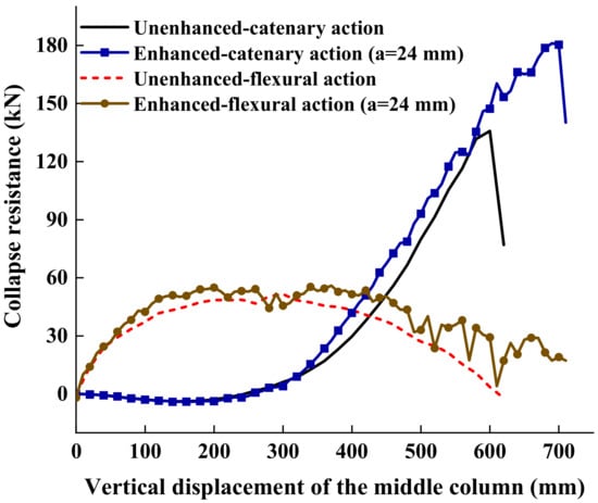
Figure 21.
Collapse resistance mechanisms of model M0-RS2-a24.
3.4. Discussions
The critical parameters describing the performance of retrofit strategy 1 and retrofit strategy 2 in improving the progressive collapse behavior of gravity frames are tabulated in Table 1, including the elevation in the static and dynamic ultimate collapse resistance of the composite frames and , and the ultimate displacement under quasi-static loading condition, along with the decrease in and peak dynamic peak displacement of the planar gravity frames of the middle stub column under nominal gravity load after sudden loss of the middle column, . Combined with Figure 22, in which the comparisons between the static and dynamic behaviors of M0-RS1-8, M0-RS2-a24, and M0 subjected to loss of middle column are illustrated, it was revealed that retrofit scheme 1 slightly outperformed retrofit scheme 2 in the above-mentioned respects. The amount of steel that is required to enhance the conventional simple connections by using these two retrofit strategies and how the additional steel is attached are also compared in Table 1. Both retrofit strategies are practical because they are economical and easy to implement. However, the cost of retrofit strategy 2 should be much lower than retrofit strategy 1 because the amount of additional steel required by retrofit strategy 2 is only around 1/4 of that required by retrofit strategy 1, accounting for 0.4% of the total steel quantity of the entire frame. On the other hand, bolt holes need to be drilled on both beams and columns in retrofit strategy 1, while retrofit strategy 2 does not impair the column because the additional steel plates are welded to the column flanges.

Table 1.
Comparisons between retrofit strategy 1 and retrofit strategy 2.
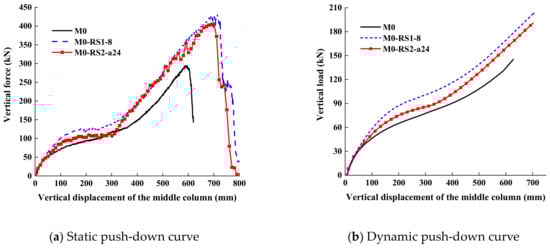
Figure 22.
Comparisons between the performance of retrofit strategy 1 and retrofit strategy 2.
4. Employment of Proposed Retrofit Strategies to Seismically Designed Steel Frame Structures
The proposed approaches were implemented to retrofit the gravity system of a 10-story prototype building, whose plan view and elevation view are shown in Figure 23a,b, respectively. The structural system is composed of special moment frames and gravity frames. Beams in gravity frames are connected to the columns through fin plate connections. Additional details about the building can be found in Alashker et al. [54]. Pin plate connections are also a type of simple connection. Similar to web cleat connections, their progressive collapse behavior is also dominated by catenary action, as shown in Yang [55]. Therefore, although the proposed retrofit strategies are developed on the basis of the collapse resistance mechanisms of web cleat connections, they are also applicable to fin plate connections. The responses of the prototype structural systems with conventional and enhanced pin plate connections are compared after an interior gravity column is forcibly removed and collided with a heavily loaded truck with high speed.
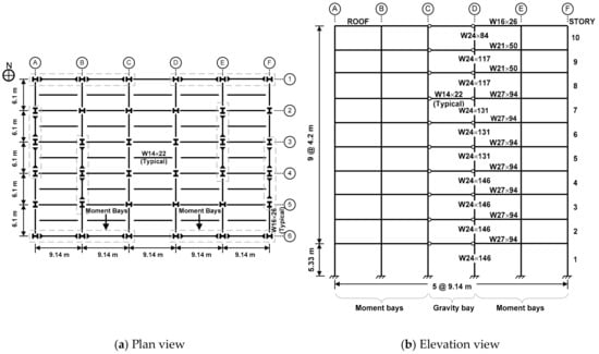
Figure 23.
Prototype building.
4.1. Modeling Approaches and Validation Studies
A 3-D micro-based finite element model of the prototype building, termed M1 in Li and El-Tawil [23] and Alashker et al. [54], is used herein. The full 3-D model is shown in Figure 24a. Compared with the physical-based finite element models, which are mainly composed of solid elements, the modeling approach adopted by M1 is simplified. The model accounts for the composite floor, steel beams and columns, and the two types of connections that are used to join the columns and beams, i.e., moment connections and fin plate connections. As shown in Figure 24b, beams and columns are modeled using fully integrated rectangular shell elements. Shear tab connections are modeled using a single row of shell elements, while the floor slab is modeled using fully integrated four-node, isotropic shell elements connected to the underlying steel beams through rigid links. More details of the model can be found in Li and El-Tawil [23] and Alashker et al. [54].
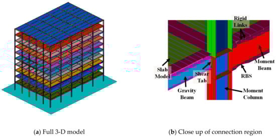
Figure 24.
Details of model M1 ([54]).
Simplified models are developed for the planar composite frames represented by Model M0, M0-RS1-8, and M0-RS2-a24 using the modeling approach of M1, as shown in Figure 25. The details of the simplified models for the enhanced connection employing retrofit strategy 1 are presented in Figure 25c. The seat angle is modeled using fully integrated rectangular shell elements with a size of approximately 8 mm, and the bolts are modeled using beam elements. The inelastic stress–strain responses of seat angles and bolts are both represented by J2 plasticity models calibrated against experimental data. The bolt holes in the seat angle are physically considered. According to the simulation results of M0-RS1, the failures of the enhanced connections are initiated by the failures of the vertical leg of the seat angle connected to the column flange due to the contact between the bolt head and the seat angle. On the other hand, the shear responses of the bolts also need to be reasonably captured. Therefore, in order to consider these aspects, the bolts’ nodes are connected to the nodes of the bolt holes using rigid links. The other end of the bolt element is connected to the beam or column surface because it is reasonable to assume that the bolt is clamped by the flange. In the simplified model representing the simple connection enhanced using retrofit strategy 2, which is presented in Figure 25d, the additional steel plate is modeled using shell elements with an opening at the center whose width is equal to the two long slotted holes. The bolts sliding along the long slots are modeled using discrete beam elements, which are only permitted to deform axially within the plane of the additional steel plate. The discrete beam elements are connected to the beam flange using rigid links, and their nodes are connected to the column surface. No resistance is generated initially within the discrete beam elements to model the slide of the bolts along the long slots before they are in contact with the edges of the long slots. After that, the displacement-force responses of these discrete beam elements are represented using a bilinear relationship obtained on the basis of the simulation results of the detailed finite element model representing the response of a bolt in single shear.
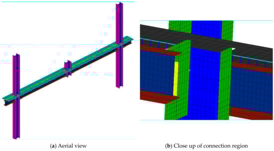
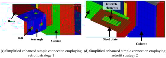
Figure 25.
Simplified unenhanced and enhanced planar composite frame model.
The comparisons between the detailed and simplified models for unenhanced and enhanced planar composite frames with simple connections are illustrated in Figure 26. Generally speaking, there is good agreement between the results of these two types of models. The variants of model M1, in which all simple connections are strengthened by using retrofit strategy 1 and retrofit strategy 2, are termed as M1-RS1 and M1-RS2, in which simplified modeling approaches are adopted by the enhanced connections.
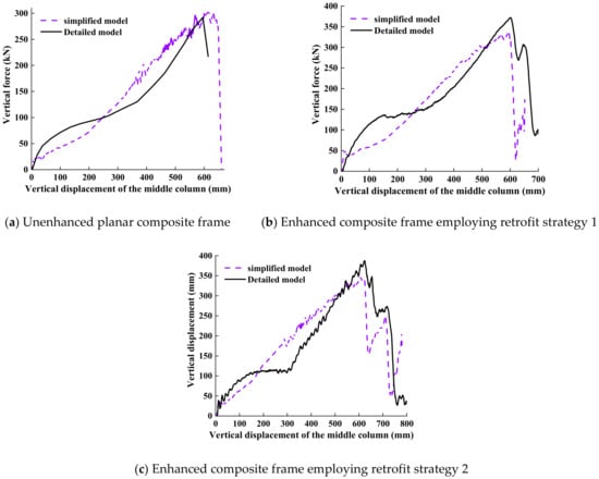
Figure 26.
Comparisons between detailed models and simplified models.
4.2. Comparisons between M1 vs. M1-RS1/M1-RS2 Subjected to Sudden Loss of an Interior Gravity Column
Dynamic nonlinear analysis was performed using models M1, M1-RS1, and M1-RS2 within the alternate path method (APM) setting. Each model is firstly loaded with gravity loads within 1 sec, followed by a wait period of 0.5 sec in order to eliminate the vibration associated with the loading process. Then an interior gravity column in the first floor, D5 (Figure 23a), is suddenly removed and the responses of the models, which are allowed to respond to the new boundary, are investigated.
The simulation results of M1 reveal that the removal of D5 led to progressive collapse of the prototype structure. The collapse sequence is demonstrated by Figure 27. The damage was initiated by the failures of the shear connections attached to column D5, indicating the shear connections are not capable of developing adequate catenary action to resist redistributed gravity loads. Collapse was arrested in both M1-RS1 and M1-RS2. The relationships between the displacement of the node at the top of the removed column versus time in M1-RS1 and M1-RS2 are plotted in Figure 28. The peak dynamic displacements of M1-RS1 and M1-RS2 at the removed columns were 514 and 744 mm, settling down at 497 and 727 mm, respectively. Although the deformation in model M1-RS2 was larger than M1-RS1, it was well below the maximum failure displacement, which is about 1300 mm as discussed in Alashker et al. [54]. Therefore, both retrofit strategies successfully increase the robustness of the seismically designed structural system and prevent progressive collapse from happening under column loss scenario.
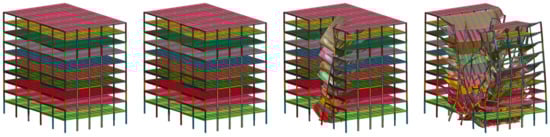
Figure 27.
Response of model M1 subjected to sudden loss of column D5.
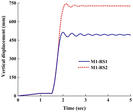
Figure 28.
Responses of model M1-RS1 and M1-RS2 subjected to sudden loss of column D5.
4.3. Comparisons between M1 vs. M1-RS1/M1-RS2 Subjected to Vehicle Impact
It is of great interest to figure out whether the structure with conventional and enhanced connections can withstand progressive collapse subjected to vehicle impact because a number of case studies conducted by the authors showed that it is possible that the damages induced by vehicle impact are more severe than those caused by instantaneous removal of a column. The Federal Highway Administration (FHWA) at the National Crash Analysis Center (NCAC) of the United States used to develop a detailed finite element model of an F800 single unit truck for the purpose of investigating heavy vehicle interactions with roadside hardware. This model, as shown in Figure 29, is used for the collision analysis. The responses of models M1, M1-RS1, and M1-RS2 subjected to the impact of the fully loaded truck, weighing 12 tons, on column D5 with a speed of 100 km/h, were investigated. In order to account for strain-rate effect, the stress–strain response of steel in the impacted column was represented using Cowper–Symonds model.
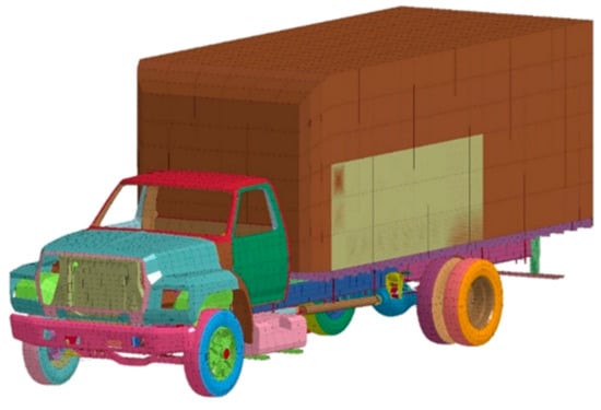
Figure 29.
F800 single unit Finite element model [56].
Similarly with the column loss scenario, the differences between the responses of these three models subjected to the truck impact are evident. Specifically, collapse is arrested in M1-RS1 and M1-RS2, but progressive building collapse occurs in model M1, as shown in Figure 30, suggesting that the structure with enhanced gravity system has adequate robustness to resist progressive collapse. After the truck collided with column D5, the nodes at the location of the removed column vibrate vertically and reach peak downward displacements of 512 and 715 mm for M2 and M1, respectively. M1 and M2 come to rest at vertical displacements of 490 and 703 mm, respectively, as shown in Figure 31. The peak displacement and steady displacement of M1-RS1 are 28% and 30% smaller than those of M1-RS2, indicating that retrofit strategy 1 is more efficient in reducing overall deflection of the structure.
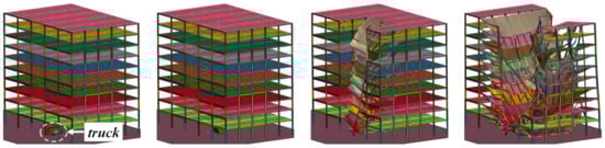
Figure 30.
Response of model M1 subjected to truck impact of column D5.
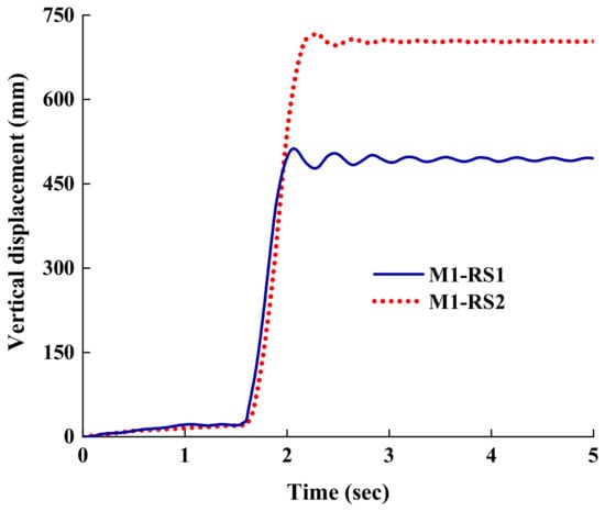
Figure 31.
Responses of model M1-RS1 and M1-RS2 subjected to truck impact of column D5.
5. Summary and Conclusions
This paper presents two retrofitting strategies against progressive collapse of existing steel gravity frames, in which beams and columns are connected by simple connections. Retrofitting scheme 1 incorporates the addition of seat angles which are bolted to beam and column flanges, whereas retrofitting scheme 2 strengthens the connections by using steel plates with long-slotted holes which are welded to the column flanges and bolted to the beam flanges. The effectiveness of the proposed retrofit strategies in improving the robustness of structural systems is evaluated using detailed finite element models for a planar composite frame with simple beam-to-column connections and a 3-D micro-based model representing a 10-story seismically designed steel-framed structure, which is composed of moment frames and gravity frames. All numerical models have been shown to be able to capture progressive collapse behaviors of structures reasonably well after carefully calibrated against disparate experimental data and more refined numerical models.
A key conclusion that can be drawn from this study is that the proposed retrofit strategies can improve the robustness of steel gravity frames significantly. The results of static and dynamic push-down analysis carried out using detailed finite element models reveal that the static and dynamic ultimate collapse resistance of the planar composite frames with enhanced connections elevate by as much as 47.6% and 55.7%, respectively, compared with those of the composite frame with conventional connections when retrofit strategy 1 is employed. The numbers become 37.5% and 45.8% if the connections are enhanced using retrofit strategy 2. The adoption of these two retrofitting strategies also results in better ductility of planar composite frames under column loss scenarios. On the basis of the quantifications of collapse resistance mechanisms, the source of additional resistance that contributes to improved structural robustness due to both retrofit strategies is the increase in the amount of catenary action. Since evident increase in the flexural stiffness of the connections is not observed, both strategies have limited impact on the seismic behavior of the entire structural system. The comparisons between the responses of a multistory seismically designed steel frame structure, whose columns and beams in the gravity system are connected by enhanced simple connections and conventional simple connections, subjected to instantaneous removal of an interior gravity column and impact of a heavy vehicle with high speed on the same column, demonstrate that the proposed retrofit strategies are able to effectively protect the structure under both column loss scenarios and extreme loading conditions because progressive collapse occurs to the structure with unenhanced gravity system whereas collapse is arrested in structures with enhanced gravity systems.
Furthermore, both schemes are economical, easy-to-implement, and non-destructive. Therefore, the proposed strategies are practical enough to be applied to retrofit existing steel gravity frames against progressive collapse.
Author Contributions
Original draft prepraration: L.Z.; supervision, methodology, retrofit strategies, numerical models and validation: H.L.; review and editing: W.W. All authors have read and agreed to the published version of the manuscript.
Funding
The presented work was supported by grants from the National Natural Science Foundation of China under Grant No. 51408152, China Postdoctoral Science Foundation through grant 2014M550194, China Postdoctoral Science Foundation through grant 2015T80353, and Natural Science Foundation of Heilongjiang Province, China under Grant No. LC2016021.
Conflicts of Interest
The authors declare no conflict of interest.
References
- ASCE. Minimum Design Loads for Buildings and Other Structures; SEI/ASCE 7-16; American Society of Civil Engineers: Reston, VA, USA, 2017. [Google Scholar]
- Yang, B.; Tan, K.H. Robustness of bolted-angle connections against progressive collapse: Mechanical modelling of bolted-angle connections under tension. Eng. Struct. 2013, 57, 153–168. [Google Scholar] [CrossRef]
- Yang, B.; Tan, K.H. Robustness of bolted-angle connections against progressive collapse: Experimental tests of beam-column joints and development of component-based models. J. Struct. Eng. 2013, 139, 1498–1514. [Google Scholar] [CrossRef]
- Fu, Q.N.; Tan, K.H.; Zhou, X.H.; Yang, B. Load-resisting mechanisms of 3D composite floor systems under internal column-removal scenario. Eng. Struct. 2017, 148, 357–372. [Google Scholar] [CrossRef]
- Li, S.; Shan, S.; Zhai, C.; Xie, L. Experimental and numerical study on progressive collapse process of RC frames with full-height infill walls. Eng. Fail. Anal. 2016, 59, 57–68. [Google Scholar] [CrossRef]
- Liu, C.; Fung, T.C.; Tan, K.H. Dynamic performance of flush end-plate beam-column connections and design applications in progressive collapse. J. Struct. Eng. 2016, 142, 04015074. [Google Scholar] [CrossRef]
- Ren, P.; Li, Y.; Lu, X.; Guan, H.; Zhou, Y. Experimental investigation of progressive collapse resistance of one-way reinforced concrete beam–slab substructures under a middle-column-removal scenario. Eng. Struct. 2016, 118, 28–40. [Google Scholar] [CrossRef]
- Shan, S.; Li, S.; Xu, S.; Xie, L. Experimental study on the progressive collapse performance of RC frames with infill walls. Eng. Struct. 2016, 111, 80–92. [Google Scholar] [CrossRef]
- Wang, W.; Fang, C.; Qin, X.; Chen, Y.; Li, L. Performance of practical beam-to-SHS column connections against progressive collapse. Eng. Struct. 2016, 106, 332–347. [Google Scholar] [CrossRef]
- Yang, B.; Tan, K.H.; Xiong, G.; Nie, S.D. Experimental study about composite frames under an internal column-removal scenario. J. Constr. Steel Res. 2016, 121, 341–351. [Google Scholar] [CrossRef]
- Kang, S.B.; Tan, K.H. Progressive collapse resistance of precast concrete frames with discontinuous reinforcement in the joint. J. Struct. Eng. 2017, 143, 04017090. [Google Scholar] [CrossRef]
- Li, H.; Cai, X.; Zhang, L.; Zhang, B.; Wang, W. Progressive collapse of steel moment-resisting frame subjected to loss of interior column: Experimental tests. Eng. Struct. 2017, 150, 203–220. [Google Scholar] [CrossRef]
- Lu, X.; Lin, K.; Li, Y.; Guan, H.; Ren, P.; Zhou, Y. Experimental investigation of RC beam-slab substructures against progressive collapse subject to an edge-column-removal scenario. Eng. Struct. 2017, 149, 91–103. [Google Scholar] [CrossRef]
- Peng, Z.; Orton, S.L.; Liu, J.; Tian, Y. Experimental study of dynamic progressive collapse in flat-plate buildings subjected to exterior column removal. J. Struct. Eng. 2017, 143, 04017125. [Google Scholar] [CrossRef]
- Qian, K.; Li, B. Effects of masonry infill wall on the performance of RC frames to resist progressive collapse. J. Struct. Eng. 2017, 143, 04017118. [Google Scholar] [CrossRef]
- Zhong, W.; Meng, B.; Hao, J. Performance of different stiffness connections against progressive collapse. J. Constr. Steel Res. 2017, 135, 162–175. [Google Scholar] [CrossRef]
- Jiang, B.; Li, G.Q.; Li, L.; Izzuddin, B.A. Experimental studies on progressive collapse resistance of steel moment frames under localized furnace loading. J. Struct. Eng. 2018, 144, 04017190. [Google Scholar] [CrossRef]
- Lu, X.; Zhang, L.; Lin, K.; Li, Y. Improvement to composite frame systems for seismic and progressive collapse resistance. Eng. Struct. 2019, 186, 227–242. [Google Scholar] [CrossRef]
- Ma, F.; Gilbert, B.P.; Guan, H.; Xue, H.; Lu, X.; Li, Y. Experimental study on the progressive collapse behaviour of RC flat plate substructures subjected to corner column removal scenarios. Eng. Struct. 2019, 180, 728–741. [Google Scholar] [CrossRef]
- Qian, K.; Li, B. Performance of precast concrete substructures with dry connections to resist progressive collapse. J. Perform. Constr. Facil. 2018, 32, 04018005. [Google Scholar] [CrossRef]
- Han, Q.; Li, X.; Liu, M.; Spencer Jr, B.F. Experimental Investigation of Beam–Column Joints with Cast Steel Stiffeners for Progressive Collapse Prevention. J. Struct. Eng. 2019, 145, 04019020. [Google Scholar] [CrossRef]
- Shan, S.; Li, S.; Wang, S. Effect of infill walls on mechanisms of steel frames against progressive collapse. J. Constr. Steel Res. 2019, 162, 105720. [Google Scholar] [CrossRef]
- Li, H.; El-Tawil, S. Three-dimensional effects and collapse resistance mechanisms in steel frame buildings. J. Struct. Eng. 2014, 140, A4014017. [Google Scholar] [CrossRef]
- Alogla, K.; Weekes, L.; Augusthus-Nelson, L. A new mitigation scheme to resist progressive collapse of RC structures. Constr. Build. Mater. 2016, 125, 533–545. [Google Scholar] [CrossRef]
- Gerasimidis, S.; Sideri, J. A new partial-distributed damage method for progressive collapse analysis of steel frames. J. Constr. Steel Res. 2016, 119, 233–245. [Google Scholar] [CrossRef]
- Arshian, A.H.; Morgenthal, G. Three-dimensional progressive collapse analysis of reinforced concrete frame structures subjected to sequential column removal. Eng. Struct. 2017, 132, 87–97. [Google Scholar] [CrossRef]
- Brunesi, E.; Parisi, F. Progressive collapse fragility models of European reinforced concrete framed buildings based on pushdown analysis. Eng. Struct. 2017, 152, 579–596. [Google Scholar] [CrossRef]
- Ding, Y.; Song, X.; Zhu, H.T. Probabilistic progressive collapse analysis of steel-concrete composite floor systems. J. Constr. Steel Res. 2017, 129, 129–140. [Google Scholar] [CrossRef]
- Feng, P.; Qiang, H.; Qin, W.; Gao, M. A novel kinked rebar configuration for simultaneously improving the seismic performance and progressive collapse resistance of RC frame structures. Eng. Struct. 2017, 147, 752–767. [Google Scholar] [CrossRef]
- Jiang, J.; Li, G.Q. Progressive collapse analysis of 3D steel frames with concrete slabs exposed to localized fire. Eng. Struct. 2017, 149, 21–34. [Google Scholar] [CrossRef]
- Pham, A.T.; Lim, N.S.; Tan, K.H. Investigations of tensile membrane action in beam-slab systems under progressive collapse subject to different loading configurations and boundary conditions. Eng. Struct. 2017, 150, 520–536. [Google Scholar] [CrossRef]
- Pham, A.T.; Tan, K.H.; Yu, J. Numerical investigations on static and dynamic responses of reinforced concrete sub-assemblages under progressive collapse. Eng. Struct. 2017, 149, 2–20. [Google Scholar] [CrossRef]
- Gernay, T.; Gamba, A. Progressive collapse triggered by fire induced column loss: Detrimental effect of thermal forces. Eng. Struct. 2018, 172, 483–496. [Google Scholar] [CrossRef]
- Li, L.L.; Li, G.Q.; Jiang, B.; Lu, Y. Analysis of robustness of steel frames against progressive collapse. J. Constr. Steel Res. 2018, 143, 264–278. [Google Scholar] [CrossRef]
- Yu, J.; Luo, L.; Li, Y. Numerical study of progressive collapse resistance of RC beam-slab substructures under perimeter column removal scenarios. Eng. Struct. 2018, 159, 14–27. [Google Scholar] [CrossRef]
- Stephen, D.; Lam, D.; Forth, J.; Ye, J.; Tsavdaridis, K.D. An evaluation of modelling approaches and column removal time on progressive collapse of building. J. Constr. Steel Res. 2019, 153, 243–253. [Google Scholar] [CrossRef]
- Eren, N.; Brunesi, E.; Nascimbene, R. Influence of masonry infills on the progressive collapse resistance of reinforced concrete framed buildings. Eng. Struct. 2019, 178, 375–394. [Google Scholar] [CrossRef]
- Crawford, J.E. Retrofit Methods to Mitigate Progressive Collapse; Report on the July 2002 National Workshop and Recommendations for Future Effort; The Multihazard Mitigation Council of the National Institute of Building Sciences: Washington, DC, USA, 2002. [Google Scholar]
- Orton, S.; Jirsa, J.O.; Bayrak, O. Carbon fiber-reinforced polymer for continuity in existing reinforced concrete buildings vulnerable to collapse. ACI Struct. J. 2009, 106, 608–616. [Google Scholar]
- Kim, J.; Shin, W.S. Retrofit of RC frames against progressive collapse using prestressing tendons. Struct. Des. Tall Spec. Build. 2013, 22, 349–361. [Google Scholar] [CrossRef]
- Qian, K.; Li, B. Strengthening and retrofitting of RC flat slabs to mitigate progressive collapse by externally bonded CFRP laminates. J. Compos. Constr. 2013, 17, 554–565. [Google Scholar] [CrossRef]
- Schachter Adaros, M.; Smilowitz, R. Challenges and considerations for the retrofit of existing structures for progressive collapse. J. Perform. Constr. Facil. 2015, 29, B4014001. [Google Scholar] [CrossRef]
- Liu, T.; Xiao, Y.; Yang, J.; Chen, B.S. CFRP strip cable retrofit of RC frame for collapse resistance. J. Compos. Constr. 2017, 21, 04016067. [Google Scholar] [CrossRef]
- Al-Salloum, Y.A.; Alrubaidi, M.A.; Elsanadedy, H.M.; Almusallam, T.H.; Iqbal, R.A. Strengthening of precast RC beam-column connections for progressive collapse mitigation using bolted steel plates. Eng. Struct. 2018, 161, 146–160. [Google Scholar] [CrossRef]
- Qian, K.; Weng, Y.H.; Li, B. Improving behavior of reinforced concrete frames to resist progressive collapse through steel bracings. J. Struct. Eng. 2019, 145, 04018248. [Google Scholar] [CrossRef]
- Qian, K.; Li, B. Strengthening and retrofitting precast concrete buildings to mitigate progressive collapse using externally bonded GFRP strips. J. Compos. Constr. 2019, 23, 04019018. [Google Scholar] [CrossRef]
- Vieira, A.D.A.; Triantafyllou, S.P.; Bournas, D.A. Strengthening of RC frame subassemblies against progressive collapse using TRM and NSM reinforcement. Eng. Struct. 2020, 207, 110002. [Google Scholar] [CrossRef]
- Liu, J.L. Preventing progressive collapse through strengthening beam-to-column connection, Part 1: Theoretical analysis. J. Constr. Steel Res. 2010, 66, 229–237. [Google Scholar] [CrossRef]
- Rezvani, F.H.; Taghizadeh MA, M.; Ronagh, H.R. Effect of inverted-V bracing on retrofitting against progressive collapse of steel moment resisting frames. Int. J. Steel Struct. 2017, 17, 1103–1113. [Google Scholar] [CrossRef]
- Ghorbanzadeh, B.; Bregoli, G.; Vasdravellis, G.; Karavasilis, T.L. Pilot experimental and numerical studies on a novel retrofit scheme for steel joints against progressive collapse. Eng. Struct. 2019, 200, 109667. [Google Scholar] [CrossRef]
- Naji, A.; Ommetalab, M.R. Horizontal bracing to enhance progressive collapse resistance of steel moment frames. Struct. Des. Tall Spec. Build. 2019, 28, e1563. [Google Scholar] [CrossRef]
- Sánchez-Olivares, G.; Espín, A.T. Design of planar semi-rigid steel frames using genetic algorithms and Component Method. J. Constr. Steel Res. 2013, 88, 267–278. [Google Scholar] [CrossRef]
- Murray, Y.D. User’s Manual for LS#DYNA Concrete Material Model 159; Report No. FHWA-HRT-05-062; Federal Highway Administration: Washington, DC, USA, 2007.
- Alashker, Y.; Li, H.; El-Tawil, S. Approximations in Progressive Collapse Modeling. J. Struct. Eng. 2011, 137, 914–924. [Google Scholar] [CrossRef]
- Yang, B. The Behaviour of Steel and Composite Structures under a Middle-Column-Removal Scenario. Ph.D. Thesis, Nanyang Technological University, Singapore, 2013. [Google Scholar]
- BMI (Battelle Memorial Institute); ORNL (Oak Ridge National Laboratory); UTK (University of Tennessee). F800 Single Unit Truck FEM model for Crash Simulation with LS-DYNA. 2010. Available online: https://thyme.ornl.gov/FHWA/F800WebPage/downloads/downloads.html (accessed on 1 July 2018).
© 2020 by the authors. Licensee MDPI, Basel, Switzerland. This article is an open access article distributed under the terms and conditions of the Creative Commons Attribution (CC BY) license (http://creativecommons.org/licenses/by/4.0/).