Abstract
During the Industry 4.0 era, the open source-based robotic arms control applications have been developed, in which the control algorithms apply for movement precision in the trajectory tracking paths based on direct or reverse kinematics. Therefore, small errors in the joint positions can summarize in large position errors of the end-effector in the industrial activities. Besides the change of the end-effector position for a given variation of the set-point in manipulator joint positions depends on the manipulator configuration. This research proposes a control based on Proportional Derivative (PD) Control with gravity compensation to show the robustness of this control scheme in the robotic arm’s industrial applications. The control algorithm is developed using a low-cost board like Raspberry Pi (RPI) where the Robot Operating System (ROS) is installed. The novelty of this approach is the development of new functions in ROS to make the PD control with gravity compensation in low-cost systems. This platform brings a fast exchange of information between the Kuka™ youBot robotic arm and a graphical user’s interface that allows a transparent interaction between them.
1. Introduction
Embedded systems are used nowadays for process industrial control. This kind of automation in Industry 4.0 era is called low-cost automation. The low-cost automation has a fast growth in industrial environments which are using to systems whose monitoring and control capabilities have improved their mode of operation despite their low cost.
Nowadays, the fast-growing of low-cost devices figure out the implementation of robust control systems through the use of low-cost devices, which allows reaching an unimaginable learning opportunity by creating a reference platform for research and training in the field of mobile manipulation, which allows developers, researchers, and students to write their own control and application software [1]. Technological advances have been a fundamental part of the development of systems with different structures, whose architecture and communication work under the same standard.
The progress of applications based on the internet allows distributed production environments through the interaction between integrated computer systems and physical environments, giving rise to automatic processes controlled by the well-known Cyber-Physical Systems (CPS), demonstrating the high potential it has in the productive sector [1]. Furthermore, It should be taken into account that a complete system must have several requirements, which have different applications with their own obstacles. Technological advances have been a fundamental part of the development of systems with different structures, whose architecture and communication work under the same standard.
The use of ROS as a framework for CPS into low-cost devices simplifies the communication and monitoring of the robot control status, this so-called software is installed on GNU/Linux allowing several devices to be incorporated into a distributed network, where a master node allows the rest of the nodes to communicate through TCP/IP nodes. Since ROS implement as part of the CPS architecture gives several advantages, such as modularity of the architecture allowing adaptation to other systems, redundancy is possible due to the ROS publication/subscriber scheme, in addition to allowing cross-platform access and remote control through another element connected to the same network [2]. The only restriction present is that the control system is developed under Debian, that is, of the Open Source type, due to the compatibility between operating systems [3].
When researches choose platforms compatible with ROS, communication limitations should be considered, and when developing software for robots there is a wide variety of open source languages such as C++, Python, or Java. As a low-cost device, the RPI which is considered as s Single Board Computer (SBC) card is one of the best choices regarding the use of ROS, due to its processing capacity [4].
For the control of the joints of the robotic arm, two methods have been defined, (i) the point-to-point method which is a change from the current position to the next or (ii) path determination method which is a variation in the speed of a joint until reaching the desired position. For both, extra calibration is required considering gravitational compensation, which will allow the monitoring of the final effector trajectories in an appropriate manner reducing the error in position and speed [3].
This paper shows a kinematics library made with c++ classes and methods for the youBot manipulator based on ROS software. It provides classes to represent the position, velocities, and accelerations in joint-space and task space and the mandatory conversions between them.
The aim of this research is to present the design of a control system based on PD with gravitational compensation using low-cost SBC hardware. The proposed system has a graphic interface that uses the Application Programming Interface (API) of the Kuka™ youBot robotic arm to send the positions commands. Furthermore, the leading edge of this application of ROS are the methods and classes for the development of gravitational compensation control, ROS commands enable control over open-source drivers, leading to interoperability between independent systems.
This article is structured as follows: Section 2 presents a series of related studies that encouraged the development of this work. Section 3 provides brief concepts which will allow a better understanding of the following sections. Section 4 presents the case study used for the research method. In Section 5, the design and implementation of a gravity compensation for robot control based on low-cost automation are showed. The discussion of results is presented in Section 6. Finally, the conclusions and future work are presented in Section 7.
2. Related Works
In this section, the most relevant works and researches related to the development of robot control systems based on open-source software and hardware are analyzed. The research approach proposed in this work is also described from a technical point of view, which will allow it to be related to different control platforms.
Due to their great capacity for performing repetitive tasks that can mean a problem for people’s health, the implementation of robotic arms is a powerful alternative as part of automation, in addition, robotic arms have great precision and control over different processes such as welding, painting, agriculture, foundry, palletizing, assembly and loading, and unloading applications [4,5,6,7].
Several research works [8,9,10] describe the design and prototyping of the gravity compensation used in modular robots and provide examples of robot shapes configured using the gravity compensation modules and motion experiments of the robots. In the experiments, some motions that the robots could perform and could not perform are considered due to the lack of the gravity compensation level and module rigidity as the main factor of the failures.
A novel example about robotic applications is presented in [11], where the assistance of robotics and automation allows an advanced drilling system to be developed through technological innovation that minimizes risks and provides greater efficiency and safety resulting in more controlled production.
Also in [12], it is mentioned that robot applications together with the Internet of Things (IoT) can make possible the development of advanced services that consolidate design methodologies based on distributed architectures, making possible the interaction between controllers of different origin, allowing a cross-platform work approach for generalized environments.
With the great use of robots at the industrial level, the ROS framework has been developed as a potential alternative for the control and development of robotic applications. In the research work presented in [13], software for robots is defined as a complex code to perform, because it requires large-scale software integration, this due to the compatibility that must exist between controllers and the perception between sensors and actuators. One way to manage this complexity is based on the application of ROS, mainly due to its compatibility with Open Source based systems, which allows integration and implementation on different hardware requirements.
As presented in [14], the adoption of ROS as a design platform for robotic applications has allowed the community of researchers to develop advanced mobile handling services through the control performed on the robot hardware, leading to the use of multiplatform systems which currently show greater compatibility thanks to the integration of ROS.
The evolution in robot programming has led to the development of different control algorithms, through which you can send several types of messages to the actuators in a way that allows interaction with the objects to be manipulated within the real environment to improve this interaction. As specified in [15], both for rotary or prismatic joints, its accuracy can be improved by modifying the control in its joint space because the control over the Cartesian space entails greater difficulty.
It is necessary to make a good control over the joints because an incorrect follow-up of the proposed trajectories could cause inaccurate movements causing damage to the robot or incomplete tasks. As an example, in the work presented in [10], a collection of packages consisting of different controllers and tools for the KUKA youBot is highlighted, where three different control, position, speed, and torque methods have been implemented, demonstrating through control tests, results with submillimeter precision.
Various design concepts for gravity compensation are available in the literature. The actuator power needed to support joint torque in a robotic arm caused by the weight of robot links can be a huge problem. Gravity compensation is a well-known technique in robot design to achieve equilibrium throughout the range of motion and as a result to reduce the loads on the actuator. The paper in [16] proposes an overview of gravity compensation methods applied in robotics. The characteristics of gravity compensation are disclosed and illustrated via kinematic schemes. In order to classify the considered balancing schemes three principal groups are distinguished due to the nature of the compensation force: counterweight, spring or active force developed by an auxiliary actuator. The author of this paper believes that such an arrangement of gravity compensation methods allows one to carry out a systematized analysis and provides a comprehensive view of the problem.
While benefits of the compensation of the gravity force effects seem to be more difficult to implement, it brings additional enhancement of the control quality. Several types of research works [17,18] describe approaches to the robot manipulator control based on a compensation of non-linear gravity terms and inertial terms in the robot motion equations and applying the PD or PID-type control law. Unlike the inverse dynamics methodology, the precise mathematical model of the robot is not needed, which is an important advantage, since models of robots get more than three links are usually very complex and difficult to obtain.
The research work [19] shows a gravity force methodology compensation in order to improve the control precision and efficiency. This methodology is used in a spatial manipulator for trajectory tracking control. This paper proposed a simple and practical gravity compensation algorithm that does not need complex computation of coordinate transformation and the accurate dynamic models and parameters, only needs the largest gravity torque estimation of the manipulator and the calculation of simple trigonometric function, while the algorithm is also suitable for non-parallel axis spatial manipulators with N joints.
As can be seen in this section, technological progress has allowed the development of gravity compensation algorithms solutions that have contributed to the automation of industrial processes using robotics arms, this paper proposes a low-cost platform that has covered the needs of having controllers based on gravity compensation with a high processing capacity into the IoT paradigm.
3. State of Technology
In this section, all concepts related to the development of this research will be explained.
3.1. KUKA youBot™ Robotic Arm
It is defined as a mobile manipulator developed primarily for education and research, consisting of two parts that can be used independently, a five-degree freedom robotic arm with two fingers as a clamp and an omnidirectional base, the arm’s API is compatible with ROS and can be communicated through Ethernet and EtherCAT, and at its base, it has a mini ITX PC integrated with its CPU [20].
As shown in Figure 1, the robotic arm consists of five rotary joints and a two-finger clamp in parallel as a final tool, it reaches a height of 655 mm, was designed to carry a load of up to 0.5 kg and its rotary joints can be accessed through EtherCAT, joints two, three and four have their rotational movement parallel to one axis, while joints one and five rotate in parallel to another whenever the arm points up, the maximum rotation speed of each joint is 90 deg/s while the final effector can be opened 11.5 mm for each finger. The communication protocol defined for the Kuka YouBot uses the standard Ethernet network of the Simple Open Source EtherCAT Master (SOEM) type, which allows the implementation of an open-source controller for the master [21].
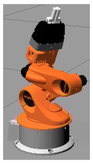
Figure 1.
Kuka™ youBot Arm.
The youBot driver has a library with classes defined in C++ that allow the control and monitoring of actuators and sensors, it provides the functionalities to establish cartesian position and velocity values, the API provided by the driver contains subsystems for handling the joints where there are classes for the arm and base [22].
3.2. Kinematics
This subsection shows the kinematics of the Kuka youBot Arm because is the basic to developing the control scheme.
The position of the final effector can be described in cylindrical coordinates, to then be transformed to the cartesian plane, direct kinematics on the geometry of the robotic arm (see Figure 2) used to get the following Equations (1)–(5).

Figure 2.
Geometry of the Kuka™ youBot Arm in the plane.
A cylindrical and effector position (see Figure 3) can be transformed from the cylindrical coordinates to the Cartesian plane using the Equations (6)–(9).
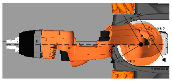
Figure 3.
Cartesian coordinate system of the Kuka™ youBot Arm.
3.3. Gravity Compensation
The field of stability control of manipulative robots has become more important since its proposal in 1981, as this only applied to robotic arms that only have rotating joints, for mathematical modeling equations are used that are nonlinear, however, Lyapunov’s theory is often used as an auxiliary means [23].
The development of the PD control with gravity compensation for manipulators is based on the assumption that the dynamics of the actuators do not exist, so it should be considered that the control signal is not the torque but the voltage that is applied to the motors, where the torque comes as the result of the electrical interaction of the actuators [24].
Without considering external disturbances, the mathematical model of a rigid robot that has a number n of links is described with Equation (10):
where represents matrix of symmetric manipulator inertia, is matrix of centripetal and coriolis forces, is gravitational pairs vector, is friction pairs and represents input torque vector.
The derivative proportional control algorithm with gravity compensation is defined by the correction of the joint positioning error presented by Equation (11):
where is the Proportional gain multiplied by the position error, is the Derivative gain multiplied by the speed of movement and represents the Gravitational torque compensation.
Gravitational compensation is defined as a term proportional to the position error, to which a damping consisting of the speed of movement is added, this part of the control consists of a mechanical retention that absorbs the impulses resulting from the response, suppressing peaks and oscillations, for the stationary stage it is estimated that the position of the effector or terminal tool is constant, assuming a value of zero at the speed of movement [25].
According to what is expressed in [26], the control loop with gravity compensation for robots is established as an equation that needs a constant measurement of position and speed, Equation (11), determines the dynamic model for PD control with gravitational compensation for manipulative robots.
Additionally, Figure 4 shows the block diagram equivalent to the PD control law with gravity compensation, where Kp and Kd are defined as positive symmetric matrices, however this type of optimization requires a partial knowledge of the manipulator, considering values of length, mass and rotational parameters of the components of the robotic arm.
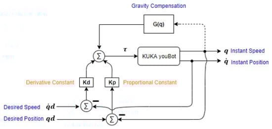
Figure 4.
Dynamic Model for PD control with gravitational compensation.
3.4. ROS
It is an open-source workspace that facilitates and speeds up the construction of robotic applications such as message delivery, package management, and hardware device drivers. Originally designed in order to simplify distributed systems, as seen in Figure 5, the building blocks of a ROS application are defined as nodes, where each is an entity that can communicate with other nodes that are part of an operating system process, the nodes supported by ROS are mainly written in C++ and Python. Nodes in a ROS environment can communicate in three ways such as Posting messages to a topic, listening to messages posted on a topic and calling a service provided by another node [27].
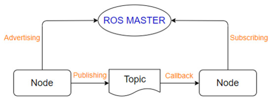
Figure 5.
Component system of a ROS model.
Initially for the management of the communication system, a master ROS must be initiated, which is responsible for allowing the nodes to meet and exchange messages, the use of topics or topics is defined as logical connection paths, where the nodes can publish topics or subscribe to them.
3.5. Raspberry Pi
Raspberry Pi is known as a low-cost single or reduced plate (SBC) computer, whose processor can be 512 MB or 1 GB of RAM. It was designed with the aim of developing computer systems, vocational training and low-level industrial application [28]. This microcontroller works with GNU/Linux operating systems such as Ubuntu, Raspbian, which are Open Source, allowing the development of versatile applications. Additionally, this card has 26 pins that allow direct interaction with the physical environment. A disadvantage is that it does not have a memory so a high-speed MicroSD must be placed so as not to affect the performance of the card.
4. Study Case
The positioning of objects is one of the most common tasks performed by robotic arms, this type of procedure requires control that allows the rotary joints to be manipulated according to the need of the process.
The present work shows the design of a control system for the robotic arm of the Kuka youBot manipulator developed on the Raspberry Pi 3B embedded card, this for the realization of a “pick and place” positioning task and the monitoring through the graphical interface which has the option to save and reproduce positions, as seen in Figure 6, the architecture is generated through the integration and cross-platform work of ROS and the youBot driver, allowing the development of libraries, topics, and nodes. The communication data and messages will be sent and received through the etherCat protocol.
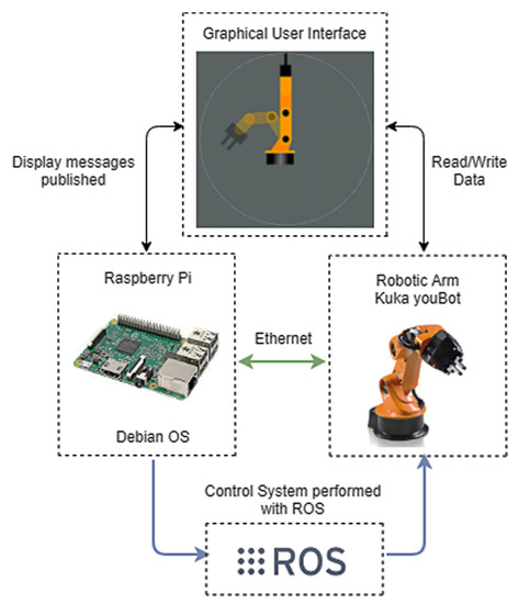
Figure 6.
Study Case Architecture.
The graphical interface allows control by sending position and velocity values through the robotic arm driver, for which classes and methods that allow data to be sent to the rotary joints are developed in C++, in addition, the manipulation through gravitational compensation control, whereby the controlled delivery of current to the joint motors ensures that there is no damage to the manipulator’s joints.
The aim of this work is to use low-cost SBC type embedded cards because are considered controllers or potential solutions to data processing and monitoring problems, being compatible with open-source. The control into SBC board is developed with gravitational compensation, which consists of the interpolation of the sent positions, so that the current values sent to the motors are regulated proportionally and derivatively, in order to make the teaching of positions more versatile this control method is included, this allows an operator handle the robotic arm according to your need manually.
5. Proposed Implementation
This section describes actions to be developed a gravitational compensation control in low-cost devices. The aim is to identify, select, process, and analyze information applied to understand the problem, thereby, allowing the reader to critically evaluate a study’s overall validity and reliability.
5.1. Instrumentation of the Joint’s Motors
The motors of the joints of the KUKA youBot arm manipulator are developed by Maxon enterprise. Specifically, the motors used are the EC 32 flat brushless series. The motor is installed in a Maxon motor-gearhead-encoder combination in a joint of youBot.
Each motor is controlled by a Trinamic TMCM-1610-KR controller board. This board is used to control the current that consumes every motor of the joints. The sensors used to close the control loop is made by galvanically isolated current transducers, characterized by a high linear range and bandwidth.
Figure 7 shows the PID closed-loop used to control de joints and measure the signal of current, velocity, and position. The torque commands are a direct function of the weight that supports every joint and the weight in the clamp, the torque target is turned into target current measurements based on the motor model.
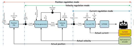
Figure 7.
Cascaded PID regulation of the joint’s motor TMCM-1610-KR controller board.
The value of the timing control given in the PID regulation loop parameter-axis parameter of the Trinamic TMCM-1610-KR controller board gives how often the PID regulator is invoked. It is given in multiple of 1 ms.
5.2. Tuning Controller Gain Matrices
For tuning the gain matrices and are done by an experimental method analyzing the step responses of every joint separately and increasing or decreasing the gains accordingly the responses. Fine-tuning is done analyzing how closely a joint space trajectory is followed and adjusting the controller gain accordingly. A starting point for the tuning of the gains is found based on the maximum applicable torques and maximized manipulator inertia matrix M
Ensuring the manual guidance of the Kuka youBot, the set-point position should be equal to the output position. When it happens the difference and the position does not influence the torque, for this reason, should be approximate to 0 and can be discarded. Based on experimentation, the matrix was found to be:
5.3. Packages Construction of ROS Application Programming Interface (API) into Raspberry Pi Card (RPi)
Most of the packages required by the Kuka youBot manipulator robot controller have been installed simultaneously with ROS Indigo.
To establish communication with the robotic arm, programming is developed through the manipulator API, it requires several controllers that must be run simultaneously and continuously so that there is no disconnection when sending orders from the RPI card.
The API provides the main libraries and the different configuration files for the robot control system, this is showed like a combination of decoupled functional subsystems, that is, the arm and the platform are defined as the set of different joints, within the API there are three main classes used to control the Manipulator, Base and Both simultaneously of the Kuka youBot.
Additionally, the API provides a hierarchy where the diagnosis of the slaves connected to the Ethercat port is included, offering the possibility of obtaining electrical parameters on the motors of the rotary joints, so that it can always work under optimal characteristics, ensuring the correct operation of the robotic arm.
The Figure 8 shows a summary of the architecture of the operation of the YouBot API, the arrows represent the data flow which occurs through EtherCAT communication, the data transfer between the user and the robot is done through a non-buffer blocking, that is, the driver can read, write and get a data message immediately.

Figure 8.
Sequence flow diagram between RPI and ROS into Kuka youBot.
- Youbot driver: is the main class of the youBot API, allows the control of the Kuka youBot using the RPI’s Ethernet port as an EtherCat communication port. The configuration file permits access to the subsystems of the platform, the arm, and the gripper through the definition of the parameters of rotary joints.
- ROS interface driver: Defines the classes and packages of the youBot driver for the control through ROS, it also contains the executable file that allows the initialization of the driver for the handshake between the RPI and the robotic arm through TCP protocol. This driver has the following packets: (i) brics_actuator this package contains all the types of messages that can be sent to the robot’s joints, the main ones being those of position, torque, and speed. (ii) std_msgs contains the type of data that is going to be sent through the user applications developed in C++, these can be of type string, float, bool, integer, among others. (iii) pr2_msgs this package defines messages and specific types of pr2 services such as detailed information about its power board and fingertip pressure sensors.
- Youbot Description: The ROS integration on the Kuka youBot includes a robot model in Unified Robot Description Format (URDF), this package describes the geometry of various elements and kinematic chains.
5.4. ROS System
For the implementation of the initially proposed study case, a ROS system with three nodes is developed as seen in Figure 9, which will allow control over the robotic arm of the Kuka youBot manipulator through an advanced method based on gravitational compensation, if the three nodes are going to be subscribers and publishers of different topics, this in order that the messages sent from the developed GUI arrive through the controller node to the physical rotary meetings, within the GUI the actions to be executed by each component are detailed through files in C++ of the same, it is described through the youBot API how the message will be published and read by the controller node, which is the core of the complete system, this will initialize the ROS master.
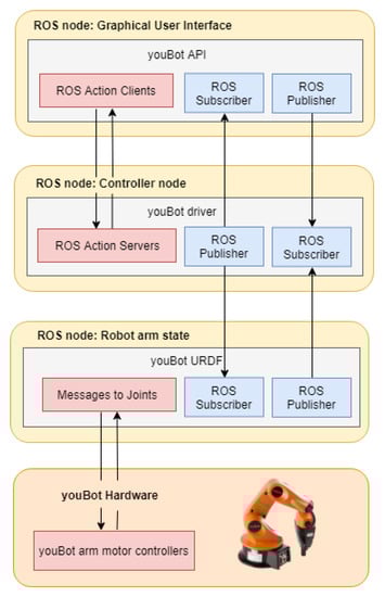
Figure 9.
ROS node Architecture.
In addition to executing the robotic arm driver with its respective configurations and mainly the gravitational compensation module with its certain calibration parameters, the node transmits the messages sent from the GUI through the robot in URDF format, which allows in a third node access to the hardware device through the EtherCAT protocol, this last node describes the geometry of several physical elements, with which the driver ensures that the initialized robot is the correct one for the API used, translating the messages sent to the motors as positional, velocity or torque values in current variations or specific limits.
The ROS Rqt Graph tool is used to get a real-time diagram of the iteration between nodes, topics and messages, where you can observe the flow of information within the developed ROS system, the type of messages used to provide control over rotary joints of the robotic arm allow to control the motors through the youBot driver, in Figure 10, the graph obtained is presented, which is equivalent to the system proposed as a case study.
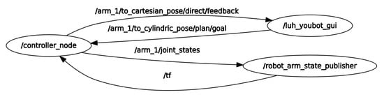
Figure 10.
Rqt ROS Graph.
The type of messages sent from the controller node to the node of the URDF robot, are sensor_msgs/JointState, these are used to transmit values in float64 format within vectors, for this a vector of 5 positions is defined, where each of them will be occupied by each of the rotary joints of the robotic arm, this corresponds to the 5 degrees of freedom and is established by the youBot API, these spaces will be filled when a position, velocity or effort type value is sent to the array, when a position has not been filled, a value of zero is assumed and this does not affect the execution of the order sent to the robotic arm.
5.5. Gravitational Compensation
The use of ROS consists of the handling of components described in C++, those that make possible the communication between ROS and the youBot controller, the included libraries allow direct access through EtherCAT for the configuration of positions and velocity on the device hardware, this tool works as a wrapper for reading and writing data in addition to the transmission of messages, facilitating the development of applications through its API, it also allows the user to transparently visualize communication between nodes, through a series of simple commands.
A new ROS node is developed that will be mainly responsible for the calibration and control of the robotic arm, for this the physical parameters required by the gravitational compensation module such as friction, mass, gravity, etc. have been previously configured.
The main class that ROS uses is called Module Gravity Compensation. This class develops the gravity compensation of every joint of the Kuka youBot Arm. This class is designed by the other two classes that are listed below (See Figure 11):
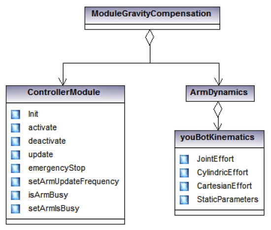
Figure 11.
Gravitational Compensation class diagram.
- Controller Module Class: The Controller Node is the central component of the driver developed. It is responsible for motion execution and trajectory planning. It provides various subscribers, service servers, and action servers for different kinds of motion commands for the manipulator and the gripper.
- Arm Dynamics Class: Robot dynamics is concerned with the relationship between the forces acting on a robot arm mechanism and the accelerations they produce. Typically, the robot mechanism is modeled as a rigid-body system, in which case robot dynamics is the application of rigid-body dynamics to robots. This class makes the gravity compensation calculation.
- youBotKinematics sub-Class: provides tools to calculate forward kinematics, inverse kinematics, and statics of the youbot manipulator.
When the gravitational compensation module is started, the above-mentioned parameters are loaded, simultaneously and automatically the initialized robotic arm calibration is performed, each rotary joint is defined as an EtherCAT slave, and for them several iterations are performed to find the most exact value in which the torque made by the motors is reduced, this is because the torque changes are proportional to those of current.
When the module is activated, the current values delivered to the joints are the minimum so that it can maintain the links statically, therefore, when applying an external force in order to manipulate the robotic arm, it does not present opposition, for which the operation of the control is verified by gravitational compensation.
5.6. Graphical User Interface
The Graphical User Interface (GUI) developed for the interactive control of the robotic arm is presented as a ROS node, which exchanges data with the controller node and this, in turn, is responsible for the control of the hardware device through a third node implemented with the robot in URDF format, the interface is developed under C++ and consists of buttons for the execution of movements through the sending of positional values or by velocity variation, as well as the activation of the control module for gravitational compensation, it also has the function for save and load states, so that the user can manually perform the positioning tasks raised in the investigation.
Within the GUI, in addition to the palette to load and save arm states, as shown in the Figure 12, a 2D visualization of the robotic arm can be shown, where two stages of this one are presented, a current one and one that will understand the objective to which the arm is to be moved, for the understanding of the possible movement made in the missing plane, three views are included that correspond to the upper detail of the first joint, the joint number 5 for the rotation of the gripper and a front of the latter to correctly visualize the opening or closing of the same. In the lower part, the current rotational parameters of the 5 joints are observed plus the longitudinal variation of the gripper, in order to maintain the positional values within the allowed ranges of each motor.
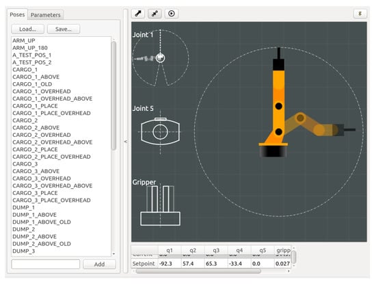
Figure 12.
Graphical User Interface.
The GUI is developed by three main classes (See Figure 13). (i) The first class is called Widget because this class displays information and provides messages to the users to interact with them. This class has two subclasses the control_arm_window which permits to get the positions of the robotic arm and the render_area class permits to generate the graphic of the robotic arm movement. (ii) The second class is called Object. This class implements the motion types of the robotic arm. The subclasses are angle_tool, cartesian_tool and vertical_angle_tool calculate forward kinematics, inverse kinematics, and statics of the youbot manipulator. The arm_side_view manages the angles of the movements to render the image. Finally, (iii) the third class is called Main this class contains all message, service, and action definitions.
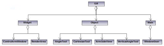
Figure 13.
UML class diagram of Graphical User Interface.
6. Discussion of Results
From 20 executions of the “Pick and Place” task, sent from the RPI to the robot arm of the Kuka youBot manipulator robot through the graphic interface, the completion time of the total process was obtained, that was from the moment in which the order is sent until the arm complies with the collection and deposit of the item to be positioned.
With the data collected from the process, the bar graph is drawing (See Figure 14). which allows seeing the dispersion of the tasks, it should be noted that when using a network connection between the RPI board and the robotic arm via ethernet, the transmission speed of data is restricted. In its version Raspberry Pi 3 Model B, has high-speed ethernet, which allows a theoretical processing capacity of 100 Mbps, together with the use of ROS, the communication becomes bidirectional between nodes, thus allowing secure control through the graphical interface and the controller node to the robotic arm.
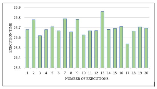
Figure 14.
Execution time of pick and place task.
To check the operation of the developed controller node, all measured values greater than 0.01 s are established as a delay, the measurements are defined in the executable file of the controller node, where the difference between the set of frequency and the operation of the robotic arm is calculated, the delay in the operation of the controller as a function of time is getting from the inverse value of the result.
The case study presents a positioning task called “pick and place”, for which the gravitational compensation module was used for the manual control of the robotic arm towards the desired positions, in addition, the saving and reproduction of positions was used through the GUI To check the operation of the same, finally, two positions were obtained for the development of the task.
As can be seen in Figure 15, which is a graphical representation of the delays obtained as a function of time, the controller does not have large delays in the execution of the gravitational compensation module, since these remain close to the established limit of 0.01 s, except for extreme cases where values suffer relatively high peaks. This delay is shown in Figure 15 is because of the torque’s motor controller of every robot’s joint due to the use of the Trinamic TMCM-1610-KR board. As explained in Section 5.1. Based on the velocity PID regulator the position PID regulator can be parameterized as PD with gravity compensation as explained in this research.
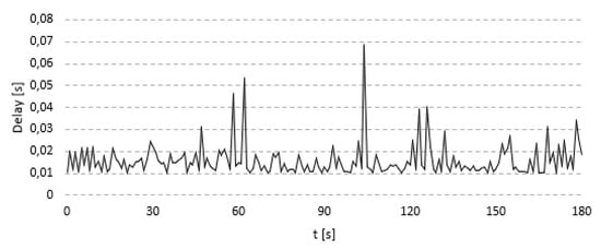
Figure 15.
Delays obtained in the study case.
The consumption of hardware resources of the Raspberry Pi 3B card is showed in Figure 16. The performance of the CPU is monitored for a period of 45 min in which the ROS master is initially started with the Kuka YouBot driver for the control of the robotic arm, and the task of positioning objects is constantly executed. The optimal working of the developed system should be highlighted since the communication link is not terminated at any time and the card is only required as a maximum up to a third of its processing capacity.
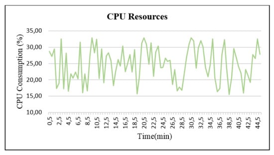
Figure 16.
RPI’s CPU consumption.
7. Conclusions and Future Work
This work shows the design of a controller node within a system developed through the ROS API and the youBot driver, mounted on a low-cost SBC card. The proposed architecture as a case study raises interoperability between hardware platforms based on open source, the elaborated application is considered as a meta-package which contains the packages and files necessary for the control of the robotic arm of the Kuka youBot manipulator through EtherCAT.
The calibration and control tasks of the rotary joints of the robotic arm for control through the gravitational compensation module, are performed in the background and automatically once the controller node has been initialized, when this process ends, it can be executed the GUI developed, which allows more intuitive control for the user since it allows to see the current position and the goal to want to reach. In addition to making possible the selection of the type of control, either by position, velocity or by the gravitational compensation module.
Future lines of research should focus on the development of different control methods based on the prediction of trajectories through direct or reverse kinematics, on the use of other types of software or protocols that allow greater limits on the interoperability of the hardware, through the application of libraries for image processing and the use of different sensors for object detection.
Author Contributions
Conceptualization, M.V.G. and J.E.-N.; methodology, C.A.G.; software, J.E.-N. and C.A.G.; validation, M.V.G.; investigation, J.E.-N., C.A.G. and M.V.G.; writing–original draft preparation, J.E.-N. and M.V.G.; writing–review and editing, M.V.G.; visualization, W.M.; supervision, M.V.G.; funding acquisition, W.M. All authors have read and agreed to the published version of the manuscript.
Funding
This work was supported by Universidad Tecnica de Ambato (UTA) and their Research and Development Department (DIDE) under project CONIN-P-256-2019, and SENESCYT by grants “Convocatoria Abierta 2011”, “Convocatoria Abierta 2013”, and “Convocatoria Abierta 2018”.
Conflicts of Interest
The authors declare no conflict of interest.
References
- Wang, L.; Törngren, M.; Onori, M. Current status and advancement of cyber-physical systems in manufacturing. J. Manuf. Syst. 2015, 37, 517–527. [Google Scholar] [CrossRef]
- Garcia, C.A.; Lanas, D.; Edison, A.M.; Altamirano, S.; Garcia, M.V. An Approach of Cyber-Physical Production Systems Architecture for Robot Control. In Proceedings of the IECON 2018—44th Annual Conference of the IEEE Industrial Electronics Society, Washington, DC, USA, 21–23 October 2018; pp. 2847–2852. [Google Scholar] [CrossRef]
- Yu, C.; Li, Z.; Liu, H. Research on Gravity Compensation of Robot Arm Based on Model Learning*. In Proceedings of the 2019 IEEE/ASME International Conference on Advanced Intelligent Mechatronics (AIM), Hong Kong, China, 8–12 July 2019; pp. 635–641. [Google Scholar]
- Lin, H.I. Design of an intelligent robotic precise assembly system for rapid teaching and admittance control. Robot. Comput. Integr. Manuf. 2020, 64. [Google Scholar] [CrossRef]
- Treesatayapun, C. Robotic architecture as unknown discrete-time system based on variable-frequency drive and adaptive controller. Robot. Comput. Integr. Manuf. 2020, 64. [Google Scholar] [CrossRef]
- Sun, P.; Li, Y.; Wang, Z.; Chen, K.; Chen, B.; Zeng, X.; Zhao, J.; Yue, Y. Inverse displacement analysis of a novel hybrid humanoid robotic arm. Mech. Mach. Theory 2020, 147. [Google Scholar] [CrossRef]
- Veronneau, C.; Denis, J.; Lebel, L.P.; Denninger, M.; Blanchard, V.; Girard, A.; Plante, J.S. Multifunctional Remotely Actuated 3-DOF Supernumerary Robotic Arm Based on Magnetorheological Clutches and Hydrostatic Transmission Lines. IEEE Robot. Autom. Lett. 2020, 5, 2546–2553. [Google Scholar] [CrossRef]
- Wong, C.Y.; Ayusawa, K.; Yoshida, E. Gravity Compensation for Impedance Control of Legged Robots Using Optimizationless Proportional Contact Force Estimation. In Proceedings of the 2018 IEEE-RAS 18th International Conference on Humanoid Robots (Humanoids), Beijing, China, 6–9 November 2018; pp. 1–9. [Google Scholar]
- Rosyid, A.; El-Khasawneh, B.; Alazzam, A. Gravity compensation of parallel kinematics mechanism with revolute joints using torsional springs. Mech. Based Des. Struct. Mach. 2020, 48, 27–47. [Google Scholar] [CrossRef]
- Sheng, W.; Jingjin, S.; Fengyu, X.; Guoping, J. Kinematic accuracy analysis of robot based on local POE. In Proceedings of the 2017 29th Chinese Control And Decision Conference (CCDC), Chongqing, China, 28–30 May 2017; pp. 4922–4927. [Google Scholar]
- Oliva, E.; Berselli, G.; Pellicciari, M.; Andrisano, A.O. An Engineering Method for the Power Flow Assessment in Servo-Actuated Automated Machinery. Robot. Comput. Integr. Manuf. 2016, 38, 31–41. [Google Scholar] [CrossRef]
- Ramalingam, A. On the value of relative comparisons in firms. Econ. Lett. 2014, 124, 446–448. [Google Scholar] [CrossRef]
- Ma, Z.; Zhu, L.; Wang, P.; Zhao, Y. ROS-Based Multi-Robot System Simulator. In Proceedings of the 2019 Chinese Automation Congress (CAC), Hangzhou, China, 22–24 November 2019; IEEE: New York, NY, USA, 2019; pp. 4228–4232. [Google Scholar] [CrossRef]
- Mishra, R.; Javed, A. ROS based service robot platform. In Proceedings of the 2018 4th International Conference on Control, Automation and Robotics (ICCAR), Auckland, New Zealand, 20–23 April 2018; pp. 55–59. [Google Scholar]
- Kapustina, O.M.; Tsyganov, D.A. Typical Computational-Experimental Tasks and Research Work of Students in the Course of Robotics. In Proceedings of the 2018 IV International Conference on Information Technologies in Engineering Education (Inforino), Moscow, Russia, 23–26 October 2018; pp. 1–4. [Google Scholar]
- Arakelian, V. Gravity compensation in robotics. Adv. Robot. 2016, 30, 79–96. [Google Scholar] [CrossRef]
- Cvejn, J.; Zapletal, M. Feedback Control of Robot Manipulators by Using Gravity and Inertial Effects Compensation. In Proceedings of the 2019 20th International Carpathian Control Conference (ICCC), Kraków-Wieliczka, Poland, 26–29 May 2019; pp. 1–6. [Google Scholar]
- Sun, L.; Yin, W.; Wang, M.; Liu, J. Position Control for Flexible Joint Robot Based on Online Gravity Compensation With Vibration Suppression. IEEE Trans. Ind. Electron. 2018, 65, 4840–4848. [Google Scholar] [CrossRef]
- Wang, Y.; Zhao, J.; Chen, Y. Gravity Compensation Algorithm of Humanoid Manipulator Trajectory Tracking Control Based on Trigonometric Function. Beijing Gongye Daxue Xuebao/J. Beijing Univ. Technol. 2019, 45, 623–630. [Google Scholar] [CrossRef]
- Zhang, B.; Gao, S. Kuka Youbot Arm Path Planning Based on Gravity. In Proceedings of the 2018 International Conference on Mechanical, Electrical, Electronic Engineering & Science (MEEES 2018), Chongqing, China, 26–27 May 2018; Atlantis Press: Paris, France, 2018. [Google Scholar] [CrossRef][Green Version]
- Garcia, C.A.; Franklin, S.L.; Mariño, C.; Villalba, W.R.; Garcia, M.V. Design of Flexible Cyber-Physical Production Systems Architecture for Industrial Robot Control. In Proceedings of the 2018 IEEE Third Ecuador Technical Chapters Meeting (ETCM), Cuenca, Ecuador, 15–19 October 2018; pp. 1–6. [Google Scholar] [CrossRef]
- Di Napoli, G.; Filippeschi, A.; Tanzini, M.; Avizzano, C.A. A novel control strategy for youBot arm. In Proceedings of the IECON 2016—42nd Annual Conference of the IEEE Industrial Electronics Society, Florence, Italy, 23–26 October 2016; pp. 482–487. [Google Scholar] [CrossRef]
- Peidró, A.; Reinoso, Ó.; Gil, A.; Marín, J.M.; Payá, L. Análisis de Estabilidad de Singularidades Aisladas en Robots Paralelos Mediante Desarrollos de Taylor de Segundo Orden. In Proceedings of the Actas de las XXXVIII Jornadas de Automática, Girón, Spain, 4–6 September 2017; Servicio de Publicaciones Universidad de Oviedo: Oviedo, Spain, 2017; pp. 821–828. [Google Scholar]
- Binazadeh, T.; Yousefi, M. Designing a Cascade-Control Structure Using Fractional-Order Controllers: Time-Delay Fractional-Order Proportional-Derivative Controller and Fractional-Order Sliding-Mode Controller. J. Eng. Mech. 2017, 143, 04017037. [Google Scholar] [CrossRef]
- De Gea Fernández, J.; Mronga, D.; Günther, M.; Knobloch, T.; Wirkus, M.; Schröer, M.; Trampler, M.; Stiene, S.; Kirchner, E.; Bargsten, V.; et al. Multimodal sensor-based whole-body control for human-robot collaboration in industrial settings. Robot. Auton. Syst. 2017, 94, 102–119. [Google Scholar] [CrossRef]
- Hernández, V.; Santibáñez, V.; Carrillo, R.; Molina, J.; López, J. Control PD de Robots: Dinámica de Actuadores y Nueva Sintonía. Rev. Iberoam. Autom. Inform. Ind. Riai 2008, 5, 62–68. [Google Scholar] [CrossRef][Green Version]
- Koubâa, A. Robot Operating System (ROS); Springer: Cham, Switzerland, 2017. [Google Scholar] [CrossRef]
- García, M.V.; Pérez, F.; Calvo, I.; Moran, G. Developing CPPS within IEC-61499 based on low cost devices. In Proceedings of the 2015 IEEE World Conference on Factory Communication Systems (WFCS), Palma de Mallorca, Spain, 27–29 May 2015; pp. 1–4. [Google Scholar]
© 2020 by the authors. Licensee MDPI, Basel, Switzerland. This article is an open access article distributed under the terms and conditions of the Creative Commons Attribution (CC BY) license (http://creativecommons.org/licenses/by/4.0/).