Abstract
The mechanical response and failure behavior of high-pressure frozen ice are essential to the technological progress in drilling thick polar ice sheets, but current research primarily focuses on non-pressure-frozen ice. In this paper, ice specimens with a cylindrical geometry were fabricated at −20 °C, applying freezing pressures across a range of 10 to 40 MPa with a 10 MPa interval. Their mechanical properties were investigated through triaxial compression tests under axial loading conditions and were compared with the results obtained at −10 °C. The results indicate that, with increasing freezing pressure, the samples transitioned from a failure state of interlaced cracking to a highly transparent state. The failure behavior observed in the specimens was characterized as ductile, as evidenced by the deviatoric stress–axial strain relationships. Moreover, the peak deviatoric stress exhibited a non-monotonic dependence on freezing pressure, with an initial rise from 9.59 MPa at 10 MPa to a peak of 14.37 MPa at 30 MPa and a subsequent decline to 10.12 MPa at 40 MPa. All specimens reached a relatively stable residual state at 5% axial strain, with residual deviatoric stresses ranging from 4.13 to 5.71 MPa. A reduction in freezing temperature from −10 °C to −20 °C can effectively enhance both the peak deviatoric stress and the residual stress of high-pressure frozen ice under triaxial shear conditions. All peak tangent modulus values, ranging from 1.61 to 2.93 GPa with an average of 2.2 GPa, were observed within 0.7% axial strain and exhibited mild fluctuations with increasing freezing pressure. These findings provide a more robust mechanical foundation for drilling research and operations in extremely thick polar ice caps.
1. Introduction
Significant natural resources, encompassing substantial marine reserves as well as diverse biological and genetic materials, are housed in the polar regions [1,2]. Additionally, dust particles [3], soluble chemical constituents [4], and trapped gases within ice cores and underlying geological bodies serve as critical archives for reconstructing past climate variability and predicting future climatic and environmental changes [5,6,7]. Currently, borehole drilling stands as the most direct and effective technical approach for both deep ice-core retrieval and subglacial environment investigation in polar regions [8]. The mechanical properties of ice, particularly its uniaxial compressive strength and triaxial shear strength, as well as the dependence of these strengths on strain rate, grain size, and growth temperature, are critical for ice sheet drilling in polar or cold-region bases [9,10]. Understanding how ice strength varies with these factors helps optimize drilling parameters, ensuring safer and more efficient drilling operations while minimizing risks to personnel and infrastructure in extreme environments [11,12].
The vast majority of Antarctica and Greenland in the Arctic is covered by ice sheets, totaling approximately 16 million km2 and accounting for about 11% of the Earth’s land area [13]. Beneath most polar ice sheets lies a vast subglacial hydrological system that encompasses subglacial lakes, streams, and other features [14,15]. A subglacial lake discovered in Princess Elizabeth Land (PEL), eastern Antarctica, lies in close proximity to areas that underwent substantial changes during Quaternary glacial cycles and Pliocene warm periods. This lake is overlain by an ice sheet approximately 3600 m thick [16,17]. Lake Vostok, also in Antarctica, is the deepest confirmed subglacial hydrological system, covered by an ice sheet approximately 4 km thick [18,19]. Isotopic studies indicate that the bottom 200 m of this ice layer consist of refrozen lake water formed under high pressure [20]. To retrieve lake water samples, Russian research teams initiated a deep ice-drilling project in the late 20th century [21]. However, a limited understanding of the mechanical behavior of the basal ice layer led to multiple unexpected water intrusions as drilling approached the ice-sheet base, significantly complicating sample collection. As ice thickness increases, basal pressures beneath ice sheets can reach tens of megapascals [22], providing a unique opportunity for atypical freezing behavior under extreme conditions. Numerous deep ice-core drilling projects in polar regions have also revealed the presence of a “brittle ice zone” at depths around 1000 m [23,24]. Ice cores retrieved from this depth range exhibit poor structural integrity and a high tendency to fracture, indicating significant changes in ice mechanical properties with increasing depth. High-pressure frozen ice (HPFI) is not only frequently encountered in polar ice sheet drilling but is also commonly observed in deep artificial ground freezing (AGF) engineering projects [25,26]. To date, AFG engineering applications have reached depths exceeding 900 m [27,28]. When localized pressure increases induced by frost heave during freezing are considered, the resulting freezing pressures can exceed 10 MPa [29]. Furthermore, numerous hydrous celestial bodies in space also face the issue of water freezing into ice under high-pressure conditions [30,31]. Therefore, studying HPFI’s mechanical behavior is thus vital to advancing key technologies in thick ice cap drilling, deep AFG engineering, and space exploration.
The mechanical properties of ice have become a major research focus, driven by the growing demands in polar scientific expeditions, offshore platform engineering, and the construction of military infrastructure in cold regions. Zhang et al. developed an enhanced low-temperature split-Hopkinson pressure bar system to investigate ice fracture dynamics. Using the notched semicircular bending method, they measured the quasi-static and dynamic fracture toughness of freshwater ice under varying loading rates and temperatures. Their results demonstrated that dynamic loading significantly enhances mode I initiation fracture toughness compared to quasi-static conditions [32]. Wang et al. conducted laboratory experiments to assess the flexural strength and uniaxial compressive strength of landfast sea ice collected from Prydz Bay [33]. The results demonstrated that the flexural strength of ice decreases with increasing porosity regardless of the brine volume, enabling the establishment of a predictive mathematical model. The uniaxial compressive strength exhibited a strain-rate-dependent behavior, increasing below a critical strain rate threshold but decreasing above it. The critical strain rate ranged from 8.0 × 10⁻⁴ to 1.5 × 10⁻³ s−1 for vertically loaded samples, and from 2.0 × 10⁻³ to 3.0 × 10⁻³ s−1 for horizontally loaded samples. Murrell et al. developed a novel servo-controlled triaxial testing system equipped with acoustic emission (AE) monitoring capabilities, along with a specialized technique for preparing pure ice specimens. Using this setup, they conducted comprehensive mechanical tests on the ice specimens, including uniaxial tension, uniaxial compression, and triaxial compression experiments [34]. The research results indicated that, under low temperatures and high strain rates, ice fractures in a pressure-dependent manner similar to brittle rocks, with strength increasing as confining pressure rises. The AE signatures also resembled those of brittle rock failure. In contrast, under higher temperatures and confining pressures, the ice exhibited ductile behavior, with strength decreasing as pressure increased. Zhang et al. conducted a study on the uniaxial compressive strength of distilled water ice grown at different temperatures (−5 °C to −35 °C) to enhance the understanding of ice strength in cold regions. Ice samples were prepared in a cryogenic laboratory [35], and their density and grain size were measured. Uniaxial compressive tests were performed at −10 °C across strain rates ranging from 10−6 s−1 to 10−2 s−1, yielding stress–strain curves, mechanical properties, and failure modes. The results revealed that ice strength follows a power-law dependence on strain rate and a linear relationship with the inverse square root of grain size. However, these above-mentioned studies were based on unpressurized freezing or shallow natural ice, and therefore cannot fully represent the behavior of HPFI. Wang et al. developed a high-pressure ice fabrication system capable of freezing water samples into standard cylindrical specimens under high pressure in a triaxial cell, and subsequently conducted uniaxial compression tests [36,37]. The experimental results demonstrated that as the freezing pressure increased sequentially from 0.5 MPa to 10, 20, and 30 MPa, the peak strength exhibited a pattern of increasing, slightly decreasing, then increasing again, confirming that freezing pressure has a significant effect on ice strength. In summary, while existing research on the mechanical properties of ice is relatively extensive, most studies have focused on shallow natural ice or artificially fabricated ice formed under atmospheric conditions. The limited research on pressure-frozen ice has primarily involved unconfined uniaxial compression tests. Therefore, triaxial testing of pressure-frozen ice remains a key area in need of further investigation.
To systematically investigate the effect of freezing pressure on the mechanical properties and failure behavior of HPFI, ice specimens with a cylindrical geometry were fabricated at −20 °C, applying freezing pressures of 10, 20, 30, and 40 MPa. The shear mechanical characteristics were comprehensively evaluated through triaxial compression tests under axial loading conditions. Through a systematic analysis of key mechanical parameters—including macroscopic deformation, stress–strain curves, peak/residual stresses, and tangent modulus evolution, this paper provides quantitative insights into the pressure-dependent behavior of frozen ice.
2. Experimental Methods
2.1. Experimental System and Apparatus
Figure 1 shows the KTL-401 triaxial experiment system, which was used for both the fabrication and triaxial compression testing of HPFI specimens. The system comprises three integrated modules: a mechanical loading unit, a thermal regulation unit, and a data acquisition unit. The mechanical control unit integrates an axial loading assembly, governed by the vertical loading frame, and a confining pressure assembly, regulated by the pressure-volume controller. This integrated system offers a 400 kN axial load capacity and a 64 MPa confining pressure capacity, with respective accuracies of 0.01% and 0.1%. To facilitate precise thermal gradient control, the triaxial chamber’s thermal regulation unit uses three dedicated refrigeration baths to supply independent cryogenic circuits at the top, side, and bottom. This setup allowed controlled initiation, directional propagation, and adjustable freezing rates of the phase transition front. The refrigeration system maintained stable temperatures as low as −40 °C (±0.1 °C). An integrated sensor network continuously monitored stress, displacement, and temperature, with data transmitted to a centralized acquisition system. To minimize thermal exchange during testing, the pressure chamber was insulated with a thermal insulation sleeve.
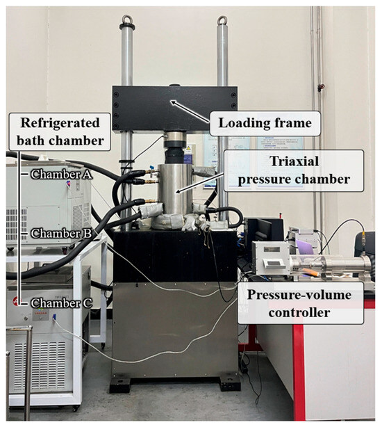
Figure 1.
The experimental system and related equipment.
The experimental system produced standard cylindrical ice specimens by directionally freezing a confined water sample along its axis within the triaxial pressure chamber. Under high confining pressure, the water expanded axially, resulting in a final specimen measuring Φ 61.8 mm × 125 mm. The working principle of the system and detailed sample preparation procedures are described in a previous publication [36]. Because both the ice specimen preparation and mechanical testing are performed entirely inside the triaxial pressure chamber, this method effectively eliminates errors caused by temperature fluctuations and stress variations during transfer, which are common in conventional approaches.
2.2. Experimental Procedure
The preparation steps before the triaxial experiment mainly include four steps: water sample preparation, water sample installation, pressure adjustment, and controlled freezing. The fabrication of cylindrical water samples constitutes a critical step in preparing standardized cylindrical frozen ice specimens. The cylindrical water sample fabrication tool, as illustrated in Figure 2, primarily consists of a spliced circular pipe fabricated from stainless steel, enabling rapid assembly and disassembly. With the temporary support of these rigid structures, a heat-shrink film is applied to their surface and thermally shrunk to set the shape. Subsequently, the temporary supporting rigid structures inside the heat-shrink film are removed, thereby forming a cylindrical water-filling cavity. Distilled water is then injected into this cavity through the upper injection hole using a syringe, ultimately forming a cylindrical water sample.
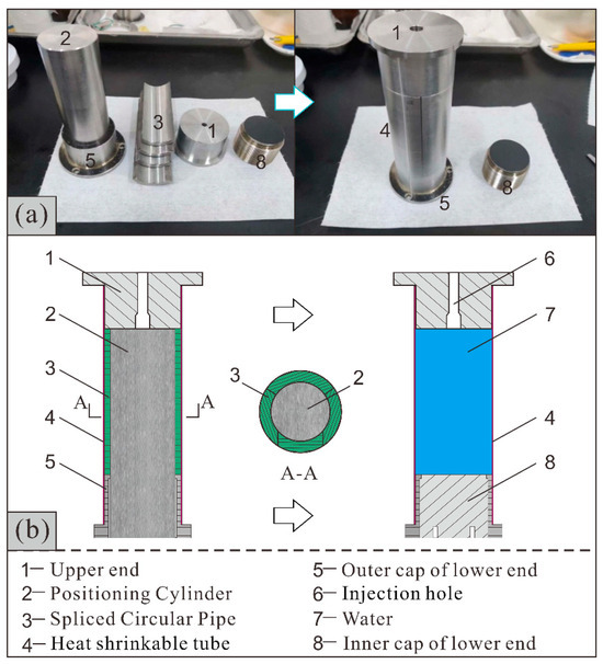
Figure 2.
Water sample preparation: (a) General view of the components; and (b) Schematic diagram of sample preparation process and principle.
Due to the negligible stiffness of water, a custom suspension frame is employed to facilitate the installation of water samples into the pressure chamber, ensuring the sample remains free from vertical compression or tensile deformation during handling (Figure 3). The suspension frame, in conjunction with a lifting mechanism, positions the water sample within the chamber, after which the upper and lower compression heads are securely fastened. Once the sample is installed, the confining pressure is applied to the water sample by gradually pressurizing the No. 10 aviation hydraulic oil that fills the chamber. Subsequently, confining pressure is gradually raised on the water sample. To prevent inward buckling of the heat-shrink tubing under axial compression, pressure application is conducted under constant axial displacement control. Specifically, the axial loading frame maintains a fixed sample height while the pressure-volume controller regulates the confining pressure, increasing it at a rate of approximately 0.2 MPa/s until the target freezing pressure is achieved.
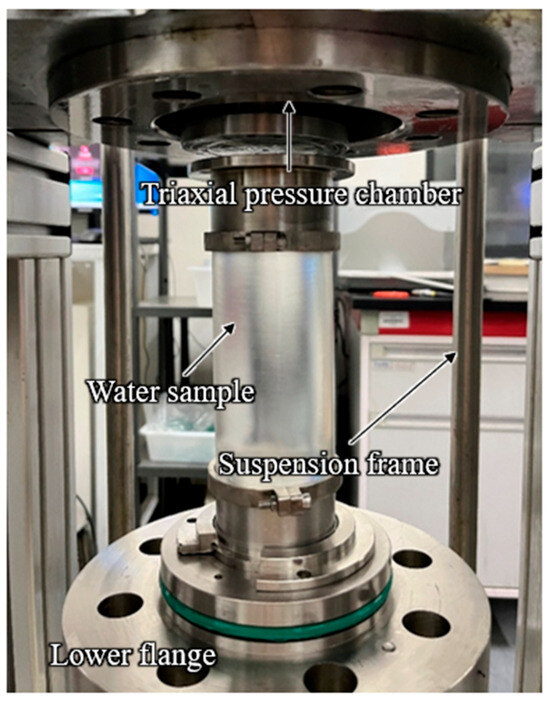
Figure 3.
Install water sample into the pressure chamber.
Upon completing pressurization, the system enters the pressure stabilization control phase. Unidirectional frost heave is constrained exclusively along the specimen’s axis through two coordinated actions. With the pressure-volume controller maintaining a constant volume during stabilization step, the axial loading frame assumes the role of regulating freezing pressure through its pressure servo mode, takes over regulation of freezing pressure. During ice formation and subsequent expansion, the confining medium restricts radial deformation while allowing axial frost heave force to dissipate, thereby promoting controlled axial specimen elongation. This controlled process ultimately produces standardized cylindrical ice samples, as depicted in Figure 4.
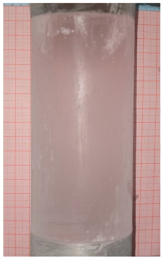
Figure 4.
Standard cylindrical pressure-frozen ice sample [36].
2.3. Experimental Scheme
The HPFI samples were fabricated at −20 °C under freezing pressures of 10, 20, 30, and 40 MPa, respectively. The mechanical tests simulated the in-situ triaxial shear stress path by maintaining the confining pressure at the initial freezing level and applying axial load at a constant strain rate of 1.5 × 10⁻⁵ s−1, in line with standard engineering practices and conventional ice testing protocols [38]. For a summary of the experimental design and key parameters, refer to Table 1.

Table 1.
Overview of the Experimental Scheme.
3. Results
3.1. Macroscopic Failure and Deformation Patterns
The general appearance of the HPFI specimens after loading the axial pressure and reaching residual strength were shown as Figure 5. The specimen frozen under 10 MPa exhibited distinct cross-cutting cracks propagating from top to bottom, with a pronounced stress concentration zone and localized failure evident in the upper-middle section. Although cracks were distributed uniformly throughout the specimen, the overall structure maintained tight interlocking connectivity. As evidenced by the relationship between the deviatoric stress and axial strain, the HPFI specimen’s mechanical behavior reveals ductile failure. Under progressive elevation of freezing pressure, the high-pressure frozen ice specimens at residual strength shifted from a fractured state to a highly transparent morphology. Simultaneously, the deformation remained concentrated in the upper section, which exhibited a white, flocculent appearance. This phenomenon distinctly contrasts with the uniaxial unconfined compression test results reported by Wang [37], where specimens exhibited dense crack networks across the freezing pressure range of 0.5 to 30 MPa. In summary, triaxial shear tests on HPFI under confining pressures of 10 to 40 MPa revealed that the failure mode did not follow the conventional geotechnical pattern of inclined shear fractures. Deformation was predominantly localized in the middle-upper section of the HPFI specimens. With rising freezing pressure, their macroscopic appearance shifted from a state of dense fracturing to a highly transparent one.
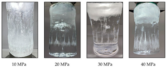
Figure 5.
Macroscopic manifestations of deformation and failure in high-pressure frozen ice specimens under various freezing pressures.
3.2. Deviatoric Stress–Axial Strain Curves
To ensure analytical accuracy, the initial adjustment phase—characterized by about 0.5% axial strain without a stress response—was excluded, and the relationship curve of deviatoric stress versus axial strain was derived and presented in Figure 6. While the evolutionary trends of the curves remained consistent under different freezing pressures, the peak and residual deviatoric stresses varied significantly with freezing pressure. Rather than exhibiting a sudden stress drop after the peak, the curves reveal a smooth decline, which is characteristic of ductile failure. All specimens reached a residual stage with relatively stable stress levels upon attaining 5% axial strain. As observed across all tests, the mechanical response, as depicted by the deviatoric stress–axial strain curves, consistently demonstrated four well-defined phases: initial elastic deformation, followed by yielding, post-peak softening, and a final residual stage. A pronounced divergence emerged between the abrupt stress transition near the peak deviatoric stress and the sustained yield plateau under unloading confining pressure [39]. In stark contrast to the rapid change, the latter exhibited a characteristically protracted yield deformation phase.
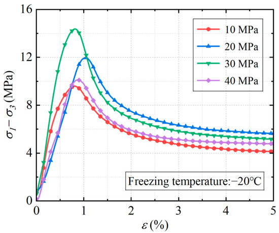
Figure 6.
Deviatoric stress response to axial strain.
4. Discussion
4.1. Peak Deviatoric Stress and Axial Stress
Figure 7 compares the dependence of peak deviatoric stress on freezing pressure for ice specimens fabricated at −20 °C and the corresponding experimental data from Zhang et al. [40] for specimens fabricated at −10 °C. It can be observed that the peak deviatoric stress in both studies exhibits the same evolutionary pattern with freezing pressure, where it initially increases until reaching a maximum value before gradually decreasing. Furthermore, the freezing pressure at the transition point increased from 20 MPa at −10 °C to 30 MPa at −20 °C. And the peak deviatoric stress of the ice under −20 °C conditions are also significantly higher than that at −10 °C, with the magnitude of increase ranging from a minimum of 25% to a maximum of 105%, resulting in an average increase of 63%. Hence, a reduction in temperature results in a considerable enhancement of the shear strength of ice. In the present experimental study at −20 °C, the peak deviatoric stress was 9.59 MPa at 10 MPa freezing pressure, and the stress reached its peak of 14.37 MPa at a freezing pressure of 30 MPa, before declining to 10.12 MPa at 40 MPa, dropping by 29.6% from the maximum.
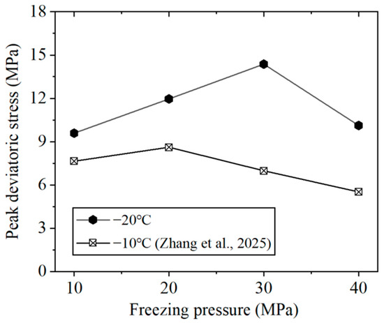
Figure 7.
Trend line showing the peak deviatoric stress response to freezing pressure [40].
To effectively reflect the axial load-bearing capacity, the peak axial stress under axial loading was statistically analyzed as a function of confining pressure, as shown in Figure 8. It can be seen that the peak axial stress exhibited a nearly linear positive correlation with freezing pressure. The peak axial stress exhibited a strong linear correlation (R2 = 0.976) with freezing pressure over the tested parameter range, mapping freezing pressures of 10 MPa and 40 MPa to stress values of 19.59 MPa and 50.12 MPa, respectively. The linear fitted equation is depicted in Figure 8.
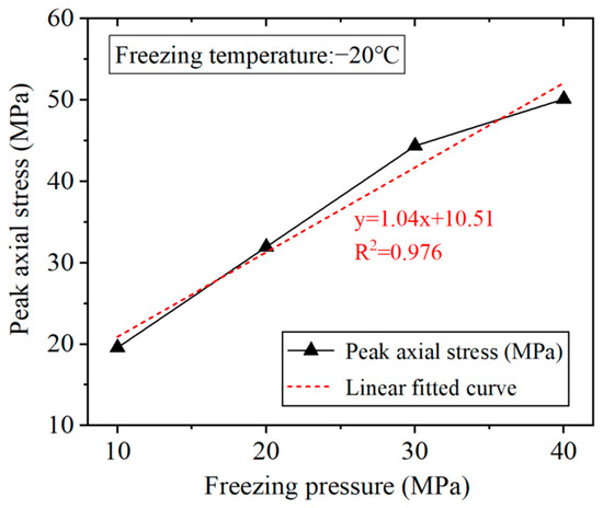
Figure 8.
Linear fitted curve of peak axial stress as a function of freezing pressure.
4.2. Residual Deviatoric Stress
The deviatoric stress–axial strain evolution curves indicate that when the axial strain of HPFI reached 5%, the stress level stabilized. The relationship between residual stress and freezing pressure for ice specimens fabricated at −20 °C is shown in Figure 9, alongside a comparison with Zhang et al.’s [40] experimental data for −10 °C specimens. It is noteworthy that the relationship between residual stress and freezing pressure is not consistent between the two temperature conditions. In this study, the −20 °C specimens demonstrate an initial increase followed by a decrease in residual stress, whereas the −10 °C condition shows a continuous decline in residual stress with increasing freezing pressure. Under identical freezing pressures, specimens fabricated at −20 °C exhibited significantly higher residual stress than those fabricated at −10 °C.
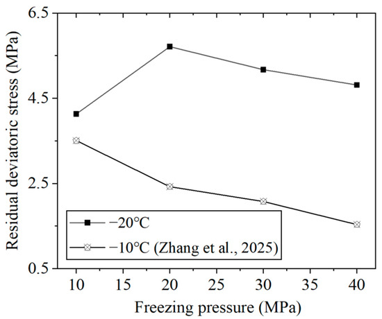
Figure 9.
Trend line showing the residual stress response to freezing pressure [40].
The experimental data obtained at −20 °C demonstrate a distinct trend, wherein the residual strength measured at a freezing pressure of 10 MPa was 4.13 MPa, followed by a transition point at 20 MPa that corresponded to the peak residual deviatoric stress of 5.71 MPa. Beyond this point, further increases in freezing pressure to 30 MPa and 40 MPa resulted in a progressive decline in stress to 5.17 MPa and 4.81 MPa, respectively, representing reductions of 9.5% and 15.8% from the maximum value. In contrast, specimens fabricated at −10 °C exhibited a markedly different behavior, with residual stresses of 3.51 MPa, 2.42 MPa, 2.08 MPa, and 1.53 MPa recorded at the corresponding freezing pressures of 10 MPa to 40 MPa, indicating a consistent and pronounced decrease as pressure increased. This clear divergence in mechanical response under varying thermal conditions substantiates the conclusion that a lower temperature effectively enhances the residual strength of ice.
4.3. Tangent Modulus
During axial compression tests under the constant strain rate, data were recorded at 1-s intervals. Directly calculating the tangent modulus from the raw stress–strain data by taking the absolute value of the slope at any point on the curve introduced significant noise. To address this, the moving average method was applied, in which each data point was smoothed by averaging 2N + 1 adjacent points. When N was set to 5, the resulting curve was sufficiently smooth for analysis. This method derived the tangent modulus-axial strain curves for each freezing-pressure condition, presented in Figure 10.
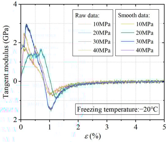
Figure 10.
Tangent modulus-axial strain curves under different freezing pressures.
The mechanical response exhibits a two-stage behavior in the tangent modulus evolution, defined by a transition at 2.5% axial strain. The initial stage is marked by significant fluctuations, wherein the tangent modulus either undergoes a sharp ascent to a distinct peak before rapidly decreasing, or rises to a near-maximum value followed by a period of oscillation prior to eventual stabilization. A critical observation is that the tangent modulus at residual strength approaches zero and demonstrates remarkable consistency, remaining virtually identical across all tested freezing pressures. Furthermore, all peak tangent modulus values were recorded within the early deformation phase of 0.7% axial strain. As illustrated in Figure 11, the corresponding peak values at freezing pressures of 10, 20, 30, and 40 MPa fluctuated between 1.61 and 2.93 GPa.
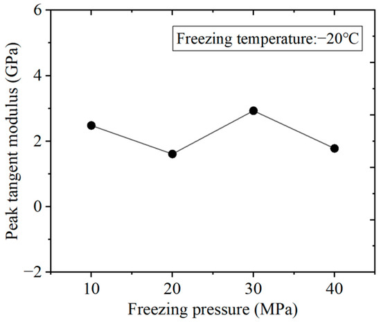
Figure 11.
Trend line showing the peak tangent modulus response to freezing pressure.
5. Conclusions
To investigate the effect of freezing pressure on the mechanical properties of high-pressure frozen ice, cylindrical ice specimens were fabricated at −20 °C, applying freezing pressures across a range of 10 to 40 MPa with a 10 MPa interval. Their shear mechanical characteristics were comprehensively evaluated through triaxial compression tests under axial loading conditions. The main conclusions are as follows.
- (1)
- As indicated by the deviatoric stress–axial strain curves, the mechanical behavior exhibited consistent ductile failure across all tests, characterized by a smooth transition near the peak stress. The peak deviatoric stress showed a non-monotonic dependence on freezing pressure, increasing to a maximum of 14.37 MPa at 30 MPa before decreasing to 10.12 MPa at 40 MPa. Notably, a reduction in freezing temperature from −10 °C to −20 °C leads to a marked improvement in the shear strength of HPFI.
- (2)
- Entry of all specimens into the residual stage occurred at 5% axial strain and was defined by stabilized stress levels. A non-monotonic dependence of residual deviatoric stress on freezing pressure was observed, characterized by an initial increase to a peak of 5.71 MPa at 20 MPa, followed by a decline at higher pressures. All peak tangent modulus values occurred within 0.7% axial strain, displaying mild fluctuations across freezing pressures, with values ranging from 1.61 to 2.93 GPa and an average value of 2.2 GPa.
- (3)
- Unlike conventional geomaterials, the deformed HPFI specimens exhibited no conventional oblique shear fractures during the triaxial tests with progressively increasing axial stress, with localized failure evident in the upper-middle section. A clear transition was observed from interconnected crack networks at 10 MPa to highly transparent failed specimens at 20–40 MPa. This increased transparency, which signifies enhanced ductility, is attributed to the suppression of crack propagation under elevated freezing pressures.
Since this study was conducted entirely in the laboratory and considered only a single temperature and stress path, its findings have inherent limitations when applied to complex engineering scenarios such as deep AGF or drilling in polar ice sheets. Future research will expand the scope to ensure the results can serve as a more reliable guide for engineering practice.
Author Contributions
Conceptualization, W.Y. and Z.Y.; methodology, W.Y., Z.Y. and Y.Z.; formal analysis, Z.Y. and T.H.; writing—original draft, Z.Y. and Y.Z.; project administration, T.H., W.Y. and Z.Y.; writing—review and editing, C.Z., Y.D. and Y.Z.; supervision, Y.D., C.Z. and T.H.; investigation, T.H., Y.Z. and C.Z. All authors have read and agreed to the published version of the manuscript.
Funding
This research was funded by China Postdoctoral Science Foundation (No. 2022M713367), the Natural Science Foundation of Jiangsu Province (No. BK20231080), the Foundation Research Project of Xuzhou (No. KC22061), and Fundamental Research Funds for the Central Universities (No. 2022QN1025).
Institutional Review Board Statement
Not applicable.
Informed Consent Statement
Not applicable.
Data Availability Statement
The original contributions presented in the study are included in the article. Further inquiries can be directed to the corresponding author.
Conflicts of Interest
The authors declare no conflicts of interest.
References
- Talalay, P.G.; Zhang, N. Antarctic mineral resources: Looking to the future of the Environmental Protocol. Earth Sci. Rev. 2022, 232, 104142. [Google Scholar] [CrossRef]
- Ergüven, N.S.; Ozsoy, B.; Yirmibeşoğlu, S.; Oktar, Ö. Regulation of Mineral Resource Activities in Antarctica. Int. J. Environ. Geoinform. 2022, 9, 81–86. [Google Scholar] [CrossRef]
- Újvári, G.; Klötzli, U.; Stevens, T.; Svensson, A.; Ludwig, P.; Vennemann, T.; Gier, S.; Horschinegg, M.; Palcsu, L.; Hippler, D.; et al. Greenland Ice Core Record of Last Glacial Dust Sources and Atmospheric Circulation. J. Geophys. Res. Atmos. Sect. 2022, 127, 23. [Google Scholar] [CrossRef]
- D’Andrilli, J.; McConnell, J.R. Polar ice core organic matter signatures reveal past atmospheric carbon composition and spatial trends across ancient and modern timescales. J. Glaciol. 2021, 67, 1028–1042. [Google Scholar] [CrossRef]
- Roman, M.; Chattová, B.; Lehejček, J.; Tejnecký, V.; Vondrák, D.; Luláková, P.; Němeček, K.; Houška, J.; Drábek, O.; Nývlt, D. Shallow depositional basins as potential archives of palaeoenvironmental changes in southwestern Greenland over the last 800 years. Boreas 2021, 50, 262–278. [Google Scholar] [CrossRef]
- Cuffey, K.M.; Paterson, W.S.B. The Physics of Glaciers; Academic Press: Cambridge, MA, USA, 2010. [Google Scholar]
- Auger, J.D.; Mayewski, P.A.; Maasch, K.A.; Schuenemann, K.C.; Carleton, A.M.; Birkel, S.D.; Saros, J.E. 2000 years of North Atlantic-Arctic climate. Quat. Sci. Rev. 2019, 216, 1–17. [Google Scholar] [CrossRef]
- Deng, Z.; Sun, Y.; Fan, X.; Talalay, P.; Yang, Y.; Liu, X.; Gong, D.; Li, B.; Wang, T.; Wu, W.; et al. Experimental Study on the Hole-Forming Process at the Borehole Bottom During Hot Water Drilling in Ice and Its Influence Mechanisms. J. Mar. Sci. Eng. 2025, 13, 817. [Google Scholar] [CrossRef]
- Talalay, P.G. Mechanical Ice Drilling Technology; Springer: Singapore, 2016. [Google Scholar]
- Augustin, L.; Motoyama, H.; Wilhelms, F.; Johnsen, S.; Hansen, S.B.; Talalay, P.; Vasiliev, N. Drilling comparison in ‘warm ice’ and drill design comparison. Ann. Glaciol. 2007, 47, 73–78. [Google Scholar] [CrossRef]
- Talalay, P.; Fan, X.; Xu, H.; Yu, D.; Han, L.; Han, J.; Sun, Y. Drilling fluid technology in ice sheets: Hydrostatic pressure and borehole closure considerations. Cold Reg. Sci. Technol. 2014, 98, 47–54. [Google Scholar] [CrossRef]
- Lv, X.; Cui, Z.; Wang, T.; Wen, Y.; Liu, A.; Wang, R. Research into mechanical modeling based on characteristics of the fracture mechanics of ice cutting for scientific drilling in polar regions. Cryosphere 2024, 18, 3351–3362. [Google Scholar] [CrossRef]
- Singh, V.; Singh, P.; Haritashya, U. Encyclopedia of Snow, Ice and Glaciers; Springer: Dordrecht, The Netherlands, 2011. [Google Scholar]
- Siegert, M.J.; Ross, N.; Le Brocq, A.M. Recent advances in understanding Antarctic subglacial lakes and hydrology. Philos. Trans. R. Soc. A Math. Phys. Eng. Sci. 2016, 374, 20140306. [Google Scholar] [CrossRef]
- Siegert, M.J. A 60-Year International History of Antarctic Subglacial Lake Exploration; Geological Society London Special Publications: London, UK, 2017. [Google Scholar]
- Jamieson, S.S.; Ross, N.; Greenbaum, J.S.; Young, D.A.; Aitken, A.R.; Roberts, J.L.; Blankenship, D.D.; Bo, S.; Siegert, M.J. An extensive subglacial lake and canyon system in Princess Elizabeth Land, East Antarctica. Geology 2016, 44, 87–90. [Google Scholar] [CrossRef]
- Yan, S.; Blankenship, D.D.; Greenbaum, J.S.; Young, D.A.; Li, L.; Rutishauser, A.; Guo, J.; Roberts, J.L.; van Ommen, T.D.; Siegert, M.J.; et al. A newly discovered subglacial lake in East Antarctica likely hosts a valuable sedimentary record of ice and climate change. Geology 2022, 50, 949–953. [Google Scholar] [CrossRef]
- Siegert, M.J.; Kwok, R.; Mayer, C.; Hubbard, B. Water exchange between the subglacial Lake Vostok and the overlying ice sheet. Nature 2000, 403, 643–646. [Google Scholar] [CrossRef] [PubMed]
- Litvinenko, V.; Trushko, V. Modelling of geomechanical processes of interaction of the ice cover with subglacial Lake Vostok in Antarctica. Antarct. Sci. 2025, 37, 39–48. [Google Scholar] [CrossRef]
- Jouzel, J.; Petit, J.R.; Souchez, R.; Barkov, N.I.; Lipenkov, V.Y.; Raynaud, D.; Stievenard, M.; Vassiliev, N.I.; Verbeke, V.; Vimeux, F. More than 200 meters of lake ice above subglacial Lake Vostok, Antarctica. Science 1999, 286, 2138–2141. [Google Scholar] [CrossRef]
- Lukin, V.; Bulat, S. Vostok Subglacial Lake: Details of Russian Plans/Activities for Drilling and Sampling. Geophys. Monogr. Ser. 2011, 192, 187–197. [Google Scholar]
- Wright, P.J.; Harper, J.T.; Humphrey, N.F.; Meierbachtol, T.W. Measured basal water pressure variability of the western Greenland Ice Sheet: Implications for hydraulic potential. J. Geophys. Res. Earth Surf. 2016, 121, 1134–1147. [Google Scholar] [CrossRef]
- Neff, P.D. A review of the brittle ice zone in polar ice cores. Ann. Glaciol. 2014, 55, 72–82. [Google Scholar] [CrossRef]
- Gow, A.J. Relaxation of Ice in Deep Drill Cores from Antarctica. J. Geophys. Res. 1971, 76, 2533–2541. [Google Scholar] [CrossRef]
- Hu, J.; Yao, Z.; Xu, Y.; Wang, R.; Hu, K. The preparation and performance research and application of high performance steel fiber reinforced concrete in deep and large freezing shaft. Mater. Res. Express 2025, 12, 055501. [Google Scholar] [CrossRef]
- Farazi, A.H.; Quamruzzaman, C. Structural design of frozen ground works for shaft sinking by practicing artificial ground freezing (AGF) method in Khalashpir coal field. Int. J. Eng. Sci. 2013, 2, 69–74. [Google Scholar]
- Yang, Q.W. Bearing Characteristics and Design Method of-Double-Layer Combined Shaft Lining in Water-Rich Strata. Ph.D. Thesis, China University of Mining & Technology, Xuzhou, China, 2023. (In Chinese). [Google Scholar]
- Zhang, C.; Wang, S.; Zhang, T.; Li, D.; Chen, H. Development and Preliminary Application of Temperature Stress Test Machine for Cast-in-Place Inner Shaft Lining. Materials 2023, 16, 4351. [Google Scholar] [CrossRef]
- Bo, D. Hydraulic Load of Underground Structure Inpore Water Bearing Rock. Ph.D. Thesis, China University of Mining & Technology, Xuzhou, China, 2015. (In Chinese). [Google Scholar]
- Carr, M.H.; Belton, M.J.; Chapman, C.R.; Davies, M.E.; Geissler, P.; Greenberg, R.; McEwen, A.S.; Tufts, B.R.; Greeley, R.; Sullivan, R.; et al. Evidence for a subsurface ocean on Europa. Nature 1998, 391, 363–365. [Google Scholar] [CrossRef]
- Roberts, J.H.; McKinnon, W.B.; Elder, C.M.; Tobie, G.; Biersteker, J.B.; Young, D.; Park, R.S.; Steinbrügge, G.; Nimmo, F.; Howell, S.M.; et al. Exploring the interior of Europa with the Europa Clipper. Space Sci. Rev. 2023, 219, 46. [Google Scholar] [CrossRef] [PubMed]
- Zhang, Y.; Wang, Q.; Han, D.; Xue, Y.; Qu, J.; Yao, H. Experimental study of the quasi-static and dynamic fracture toughness of freshwater ice using notched semi-circular bend method. Eng. Fract. Mech. 2021, 247, 107696. [Google Scholar] [CrossRef]
- Wang, Q.; Li, Z.; Lu, P.; Li, Z. Flexural and compressive strength of the landfast sea ice in the Prydz Bay, East Antarctic. Cryosphere 2022, 16, 1941–1961. [Google Scholar] [CrossRef]
- Murrell, S.A.F.; Sammonds, P.R.; Rist, M.A. Strength and Failure Modes of Pure Ice and Multi-Year Sea Ice Under Triaxial Loading. In Ice-Structure Interaction; Springer: Berlin/Heidelberg, Germany, 1991. [Google Scholar]
- Zhang, Y.; Qian, Z.; Lv, S.; Huang, W.; Ren, J.; Fang, Z.; Chen, X. Experimental investigation of uniaxial compressive strength of distilled water ice at different growth temperatures. Water 2022, 14, 4079. [Google Scholar] [CrossRef]
- Wang, B.; Sun, P.; Luo, T.; Zhang, T.; Yang, W. Freezing Pressurized Water into a Standard Cylindrical Ice Sample in a Triaxial Cell. Geofluids 2021, 2021, 6678966. [Google Scholar] [CrossRef]
- Wang, B.; Yang, W.; Sun, P.; Huang, X.; Zhang, Y.; Chen, F. Experimental study on the influence of freezing pressure on the uniaxial mechanical properties of ice. Adv. Civ. Eng. 2021, 2021, 8651467. [Google Scholar] [CrossRef]
- Sun, P. Triaxial Compression Mechanical Properties and Strength Formation Mechanism of In-Situ High-Pressure Frozen Columnar Ice Samples. Ph.D. Thesis, China University of Mining & Technology, Xuzhou, China, 2024. (In Chinese). [Google Scholar]
- Zhang, Y.; Yang, W.H.; Yang, Z.J.; Ding, Y.; Zhang, C.Y.; Sun, P.X.; Wang, B.S.; Yu, Q.B.; Zou, C. Study on the mechanical characteristics and macro-microfailure mechanisms of deep high-pressure frozen ice underconfining pressure unloading conditions. J. Min. Saf. Eng. 2025, 4, 915–924. (In Chinese) [Google Scholar]
- Zhang, Y.; Yang, Z.; Han, T.; Ding, Y.; Yang, W.; Sun, P. Experimental Simulation of In Situ Axial Loading on Deep High-Pressure Frozen Ice. Appl. Sci. 2025, 15, 10042. [Google Scholar] [CrossRef]
Disclaimer/Publisher’s Note: The statements, opinions and data contained in all publications are solely those of the individual author(s) and contributor(s) and not of MDPI and/or the editor(s). MDPI and/or the editor(s) disclaim responsibility for any injury to people or property resulting from any ideas, methods, instructions or products referred to in the content. |
© 2025 by the authors. Licensee MDPI, Basel, Switzerland. This article is an open access article distributed under the terms and conditions of the Creative Commons Attribution (CC BY) license (https://creativecommons.org/licenses/by/4.0/).