Abstract
Piles provide a convenient solution for heavy structures, where the foundation soil bearing capacity, or the tolerable settlement may be exceeded due to the applied loads. In cohesionless soils, the two frequently used pile installation methods are driving and drilling (or boring). This paper reviews the results of a large database of pile load tests of driven and drilled piles in cohesionless soils at various locations worldwide. The load test results are compared with the static analysis design method for single piles recommended in the Canadian Foundation Engineering Manual (CFEM) and other codes and standards such as the American Association of State Highway and Transportation Officials, Federal Highway Administration, American Petroleum Institute, Eurocode, and the Naval Facilities Engineering Command. An improved pile design procedure is proposed linking the pile design coefficients and to the friction angle of the soil, rather than employing the generalized soil type grouping scheme previously used in the CFEM. This improvement included in the new version of the CFEM 2021 produces a more unified value of the pile capacity calculated by different designers, reducing the obtained design capacity discrepancies.
1. Introduction
The design of deep foundations is often based on a combination of experience and empiricism [1]. In recent decades, a gradual change in design methodology has developed from empirical models to a more theoretically based approach. Furthermore, advanced methods of pile analysis have been made possible by the availability of robust software programs [2]. The pile design process begins with the selection of an appropriate pile type, depending on the site, followed by an estimation of the interaction between the pile and the surrounding soil after installation [3]. The quality and capacity of deep foundations depend on factors such as the construction method, installation equipment, and workmanship. New methods are currently investigated for piling in cohesionless soil such as the sand compaction pile method (SCP) [4].
Deep foundations are generally used to transfer loads from superstructures to foundation soils in cases where the use of shallow foundations is not feasible. Besides, in some cases, piled rafts are used to withstand heavy loads from high rise buildings offering some advantages in terms of serviceability and efficient use of materials [5,6]. According to the load transfer mechanisms for vertical loading, two pile types can be identified: (a) End bearing piles, where the majority of the load is transferred via the pile tip by bearing; and (b) friction piles, where the majority of the load is transferred by friction throughout the pile length. It should be noticed that the uplift forces on the supporting piles should be considered when the structure is founded below the water table or due to the swelling impact of the surrounding soils [7]. Furthermore, in case of loose soil, the buckling impact should be investigated for end bearing piles under loading and unloading conditions [8]. To assess theoretical methods for calculating the ultimate capacity, full-scale load tests on random piles are recommended, especially for complex and large projects. The ultimate pile capacity is usually defined as the point where the pile settlement increases rapidly under a sustained or slightly increased test load [9]. Thus, the actual capacity is determined by applying some criterion to the load-settlement data recorded in full-scale tests. Several reports present methods that can be used to evaluate the actual capacity of a single pile [10,11,12,13]. Some of these methods have been considered in the present analysis, using different criteria to define the actual capacity utilizing the relationship between the applied load and the corresponding pile head settlement.
This paper reviews an extensive database of 135 load tests of driven and drilled piles in cohesionless soils. The pile load tests are used to evaluate the static analysis approach presented in the current Canadian Foundation Engineering Manual [14]. Furthermore, the ultimate pile capacities obtained using the CFEM method is compared with the results of other theoretical methods such as the standards of the American Association of State Highway and Transportation Officials [15], the Federal Highway Administration [16,17], the American Petroleum Institute [18,19], the Eurocode [20], and the Naval Facilities Engineering Command design method [21]. Besides, the paper considers three definitions of pile capacity evaluation from pile load tests to determine the actual ultimate pile load based on the load-displacement relationship obtained from each pile load test: namely, the Hansen 80% [22], Chin-Kondner [23,24], and the Decourt [25] methods.
Finally, an improved pile design procedure is proposed linking the pile design coefficients and to the friction angle of the soil, rather than employing the generalized soil type grouping scheme previously used in the CFEM. This improvement shall produce a more unified value of the pile capacity calculated by different designers, reducing the obtained design capacity discrepancies.
2. Pile Load Tests
When piles are used in critical projects, the design should be based not only on theoretical calculations but also on full-scale field tests of random piles to assure the expected working pile capacity. Pile load tests are the most accurate methods for determining the ultimate pile capacity. They are performed by applying a static axial load to the pile head and determine the corresponding response of the pile head. Such tests aim to ensure that the load capacity of the constructed pile is larger than the calculated capacity obtained in the design. This paper utilizes an extensive database of 135 load tests of driven and drilled (bored) piles in mostly cohesionless soils with a low percentage of silt [26,27].
During the installation of driven piles, the driving force displaces the soil while pushing the pile into the soil stratum, increasing the pile and the pile group capacities. In the case of drilled piles, boring of the soil reduces the lateral confinement around the pile, thus decreasing the capacity of the pile and the pile group. However, drilled piles are preferred in sites where pile driving is not permitted due to high vibration and noise levels. Pile load tests are usually represented by plotting the pile head settlement (displacement) on the y-axis against the applied load on the x-axis. In order to discuss and analyze the field results, three methods were used to find the ultimate load capacity of each pile. The methods used were the Hansen 80%, the Chin-Kondner, and the Decourt methods. Hansen [22] defined pile capacity as the load that results in pile head settlement four times greater than the settlement occurring at 80% of that load. This value can be determined by plotting the square root of the settlement divided by the corresponding load (√δ/P) against that settlement value (δ). Chin [23,24] applied the work performed by Kondner [28] to piles. In the Chin method, the ratio between the settlement and the corresponding load is plotted against the settlement . Then, the value of the ultimate capacity is given by the inverse of the slope of the resulting line. Finally, Decourt [25] defined a method similar to the methods of Hansen and Chin-Kondner to compute the actual pile capacity. In the Decourt method, the ratio between each load and the corresponding settlement is plotted against the load . The ultimate load is then identified by the intersection of the linear regression (using the last five points) of the curve with the x-axis (applied load).
3. Interpretation of the Friction Angle Used in the Design
As the scope of this paper is to evaluate the accuracy of the CFEM static design method currently utilized and compare it with other codes and field methods, the angle of internal friction which is used in most of these methods should be accordingly obtained utilizing the available field results. The friction angles of cohesionless soils can be estimated by using CPT results around the pile shaft and tip to calculate theoretical values for the side friction and tip bearing resistance. The following equation, presented by Kulhawy and Mayne [29], is commonly used to estimate the effective friction angle of cohesionless soils ( by using the CPT results ( and the effective overburden stress :
The friction angles of cohesionless soils can also be estimated by using the SPT field results using the following equation by Schmertmann [30].
where N60 is the modified SPT number, the effective overburden stress, and pa is the atmospheric pressure.
4. The Theoretical Static Pile Design Method for Cohesionless Soils According to the CFEM
The total ultimate capacity for driven and drilled piles can be computed via the summation of the side shaft friction () and the end bearing resistance (). The following equations present the overall criterion used to calculate the pile design value:
where:
the theoretical ultimate pile capacity force
the pile shaft resistance force
the end bearing resistance force
the average unit shaft friction along the pile length, limiting values of of about 100 kPa are recommended for displacement piles and 50 kPa for small displacement piles [31].
the bearing capacity at the pile toe, typical limiting values range from 3–5 MN/m2 for calcareous sand [2,32]
The combined shaft resistance coefficient
the coefficient of lateral earth pressure at rest
the coefficient of lateral earth pressure, for drilled piles, for low-displacement piles, and for high-displacement piles
the average effective overburden pressure along the pile shaft
the effective overburden pressure at the pile toe
the friction angle between the pile and the surrounding soil
pile side surface area
pile tip cross-section area
The values of and depend on the friction angle of the cohesionless soil along the pile and at the pile tip, respectively. As shown in Table 1, the CFEM [14] presents ranges ofand values according only to the general soil type classification. However, choosing an appropriate value from this table can be difficult if the soil classification alone is the only considered parameter. Besides, the experience of the designer in choosing appropriate values for β and may result in calculated capacities that may vary widely between different designers resulting in large discrepancies in the calculated design capacity. As shown in Table 2, according to Meyerhof [33], cohesionless soils can be classified by using different ranges of the friction angle. The analyses in this paper, therefore, suggests combining the Meyerhof [33] soil classification criterion for cohesionless soils with the CFEM ranges of values. Table 3 presents the suggested and values for ranges of relative densities and friction angles. A simple modification was introduced to the classification criterion presented in Table 2 to match those exhibited in the CFEM table (i.e., Table 1 in this paper) as presented in Table 3.

Table 1.
and values, according to CFEM, for driven and drilled (bored) piles [14].
Table 2.
Correlation between relative density, SPT N value, and the internal friction angle for different cohesionless soils [15,16,17,33].
Table 3.
Suggested and values based on the soil classification and the CFEM ranges for driven and drilled (bored) piles.
In the following analysis, the ultimate capacities of the 135 piles studied are calculated by using the and values based on the suggested classification in Table 3. These capacities are then compared with values estimated by using the other theoretical and field methods considered in this paper to evaluate the suitability of the suggested improvement.
5. Assessment of the CFEM Method for Estimating the Ultimate Pile Capacity in Cohesionless Soils
In accordance with the full-scale pile load tests described in Appendix A, the axial capacity for piles driven or drilled in cohesionless soil is calculated by using the CFEM static pile design method on the basis of the values suggested in Table 3. The results are then compared with results calculated from other codes and standards to assess the theoretical approach followed by the CFEM. In addition, the Hansen 80%, Chin-Kondner, and Decourt field methods are used to obtain the maximum actual capacity from the pile load-movement curves, and the values are also compared with those calculated by using the CFEM.
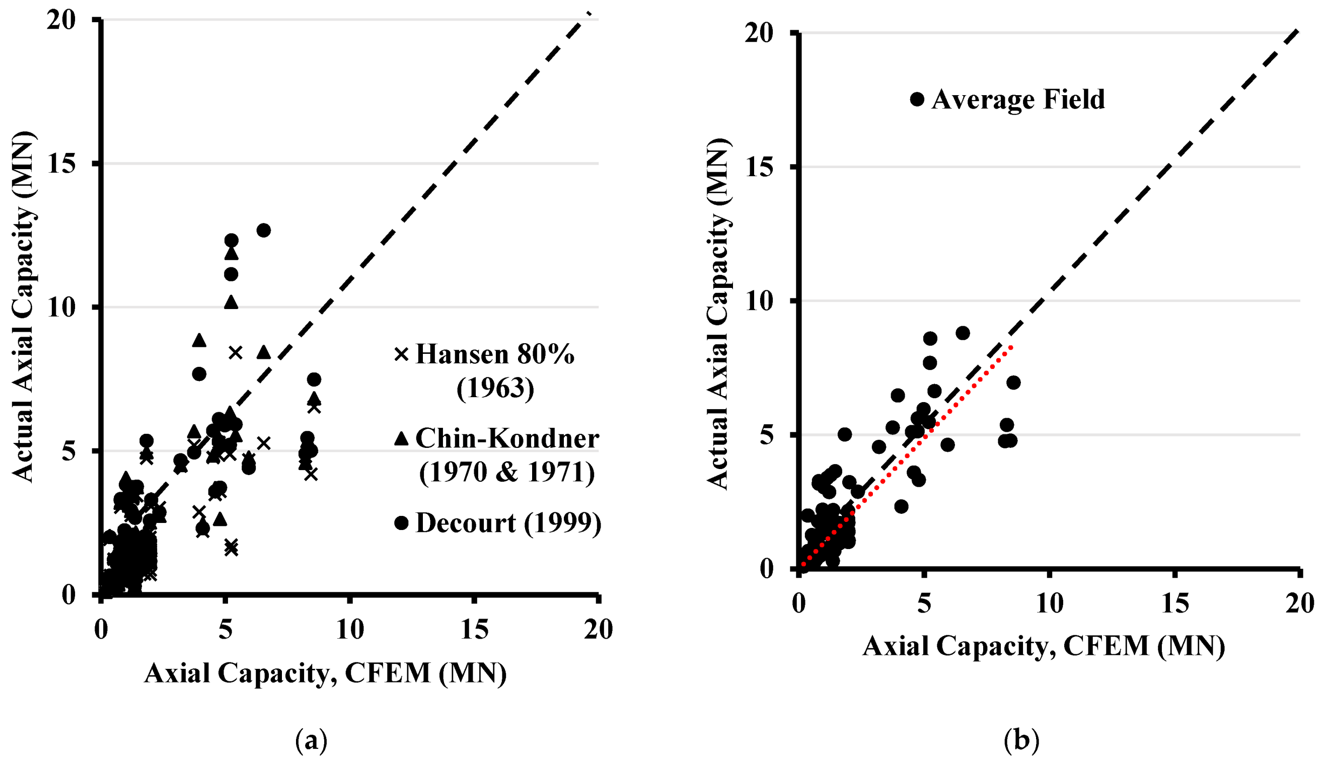
In the case of driven piles, it can be seen from Figure 1 that the majority of the axial capacities calculated by the CFEM method are lower when compared to the ASHTOO/FHWA, Eurocode, and the NAVFAC methods. However, the CFEM was found to produce a higher capacity when compared to the API design method, however, it is worth mentioning that the API was developed mainly for offshore piling. Figure 2a compares the pile capacities determined from the field results and the theoretical axial capacity calculated using the CFEM method. It can be noted from Figure 2a that most of the CFEM calculated pile capacities are comparable to the actual capacities obtained from the field methods with some variations. They are very close to capacities determined according to the Decourt [25] method. Likewise, it can be seen from Figure 2b that the average capacities for all field methods are close to the capacities calculated by the CFEM. Hence, it can be concluded that the axial load capacities for driven piles calculated using the CFEM method are within an acceptable range of the actual capacities.
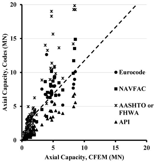
Figure 1.
Comparison between results of other design codes and the theoretical axial capacity in driven piles determined using the CFEM method.
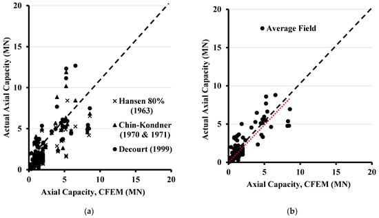
Figure 2.
Comparison between the theoretical axial capacity in driven piles determined using the CFEM method and (a) the field results, and (b) the average field results.
In the case of drilled (bored) piles, Figure 3 shows that most axial capacities calculated by the CFEM method are lower when compared to the Eurocode, the API, and the NAVFAC methods. However, the CFEM was found to produce a slightly higher capacity than the ASHTOO/FHWA design method. Figure 4a presents a comparison between the pile capacities determined from the field results and the theoretical axial capacity calculated using the CFEM method. It can be noted from Figure 4a that most of the CFEM calculated pile capacities are lower than the actual capacities obtained from the field methods and are very close to capacities determined according to the Decourt [25] method. Likewise, it can be seen from Figure 4b that the average capacities for all field methods are higher than the capacities calculated by the CFEM. Hence, it can be concluded that the axial load capacities for drilled piles calculated using the CFEM method are within a conservative range of the actual capacities.
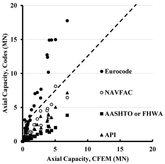
Figure 3.
Comparison between results of other design codes and the theoretical axial capacity in drilled (bored) piles determined using the CFEM.
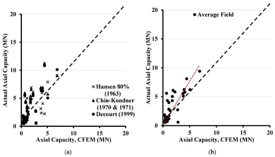
Figure 4.
Comparison between the theoretical axial capacity in drilled (bored) piles determined using the CFEM method and (a) the field results, and (b) the average field results.
6. Summary and Conclusions
Several pile design methods are used to estimate the expected pile load capacity. This paper evaluates the approach used in the CFEM for driven and drilled piles in cohesionless soils using a large database of pile load tests. The CFEM design method was also compared to the design methods from other codes and standards such as the American Association of State Highway and Transportation Officials, Federal Highway Administration, American Petroleum Institute, Eurocode, and the Naval Facilities Engineering Command. Moreover, an improved pile design procedure is proposed linking the pile design coefficients and to the friction angle of the soil, rather than employing the generalized soil type grouping scheme previously used in the current CFEM method. This improvement included in the new version of the CFEM 2021 shall produce a more unified value of the pile capacity calculated by different designers, reducing the obtained design capacity discrepancies. The results show that the CFEM static design method for driven piles gives a pile capacity that is within an acceptable range of the actual capacities. In the case of drilled (bored) piles, the CFEM values are a little bit conservative compared to the actual capacities.
Author Contributions
Conceptualization, H.E.N.; Data curation, I.E.; Investigation, H.E.N. and I.E.; Supervision, H.E.N.; Writing—original draft, H.E.N. and I.E.; Writing—review & editing, I.E. and H.E.N. All authors have read and agreed to the published version of the manuscript.
Funding
This research was funded by The Natural Sciences and Engineering Research Council of Canada (NSERC) and Divert NS grant to the first author.
Data Availability Statement
All data, models, and code generated or used during the study appear in the submitted article.
Conflicts of Interest
The authors declare that they have no known competing financial interest or personal relationships that could have appeared to influence the work reported in this paper.
Appendix A
Table A1.
Load test locations and pile properties of driven piles.
Table A1.
Load test locations and pile properties of driven piles.
| Pile Test No. | Pile Location | Loading Type | Pile Material | Pile Shape | Length (m) | Width/Diameter (m) | Thickness (m) | Reference |
|---|---|---|---|---|---|---|---|---|
| 1 | Wuhu, China | compression | concrete | open circular | 33 | 0.6 | 0.13 | Yang et al., 2015a |
| 2 | Wuhu, China | compression | concrete | open circular | 39.8 | 0.6 | 0.13 | Yang et al., 2015a |
| 3 | Wuhu, China | compression | concrete | open square | 39.8 | 0.5 | 0.095 | Yang et al., 2015a |
| 4 | Wuhu, China | compression | concrete | open circular | 29.3 | 0.6 | 0.13 | Yang et al., 2015a |
| 5 | Wuhu, China | compression | concrete | open circular | 29.2 | 0.8 | 0.13 | Yang et al., 2015a |
| 6 | Rio de Janeiro Brazil | compression | concrete | square | 37.2 | 0.5 | 0 | Tsuha et al., 2012 |
| 7 | Rio de Janeiro Brazil | compression | concrete | square | 21.4 | 0.5 | 0 | Tsuha et al., 2012 |
| 8 | Rio de Janeiro Brazil | compression | concrete | square | 35.6 | 0.7 | 0 | Tsuha et al., 2012 |
| 9 | Rio de Janeiro Brazil | compression | concrete | square | 26.5 | 0.5 | 0 | Tsuha et al., 2012 |
| 10 | Blessington Dublin, Ireland | tension | steel | open circular | 7 | 0.34 | 0.014 | Gavin et al., 2013 |
| 11 | Blessington Dublin, Ireland | tension | steel | open circular | 7 | 0.34 | 0.014 | Gavin et al., 2013 |
| 12 | Horstwalde, Germany | tension | steel | open circular | 17.61 | 0.711 | 0.0125 | Rucker et al., 2013 |
| 13 | Horstwalde, Germany | tension | steel | open circular | 17.69 | 0.711 | 0.025 | Rucker et al., 2013 |
| 14 | Horstwalde, Germany | tension | steel | open circular | 17.71 | 0.711 | 0.0125 | Rucker et al., 2013 |
| 15 | Horstwalde, Germany | tension | steel | open circular | 17.76 | 0.711 | 0.0125 | Rucker et al., 2013 |
| 16 | Horstwalde, Germany | tension | steel | open circular | 17.67 | 0.711 | 0.0125 | Rucker et al., 2013 |
| 17 | Horstwalde, Germany | tension | steel | open circular | 17.66 | 0.711 | 0.0125 | Rucker et al., 2013 |
| 18 | Horstwalde, Germany | tension | steel | open circular | 17.63 | 0.711 | 0.0125 | Rucker et al., 2013 |
| 19 | Horstwalde, Germany | tension | steel | open circular | 17.74 | 0.711 | 0.0125 | Rucker et al., 2013 |
| 20 | British Columbia, Canada | compression | steel | circular | 45 | 0.61 | 0 | Naesgaard et al., 2012 |
| 21 | Hampton, Virginia, USA | compression | concrete | square | 16.8 | 0.61 | 0 | Pando et al., 2003 |
| 22 | Rotterdam Harbor, The Netherlands | compression | concrete | square | 30.6 | 0.38 | 0 | Gijt et al., 1995 |
| 23 | Rotterdam Harbor, The Netherlands | compression | concrete | square | 30.3 | 0.38 | 0 | Gijt et al., 1995 |
| 24 | Rotterdam Harbor, The Netherlands | compression | concrete | square | 30.7 | 0.38 | 0 | Gijt et al., 1995 |
| 25 | Waddinxveen Site, The Netherlands | compression | concrete | square | 10 | 0.35 | 0 | Holscher et al., 2008 |
| 26 | Mobile Bay, AL, USA | compression | steel | open circular | 15.2 | 0.324 | 0.0254 | Mayne & Niazi, 2013 |
| 27 | ABEF Foundation, Brazil | compression | concrete | open circular | 9 | 0.5 | 0.09 | Mayne & Niazi, 2013 |
| 28 | ABEF Foundation, Brazil | compression | concrete | open circular | 7.5 | 0.5 | 0.09 | Mayne & Niazi 2013 |
| 29 | Apalachicola River, USA | compression | concrete | square | 29.9 | 0.61 | 0 | Mayne & Niazi 2013 |
| 30 | Los Angeles, CA Site, USA | compression | concrete | square | 29 | 0.61 | 0 | Mayne & Niazi 2013 |
| 31 | MS Smith, USA | compression | concrete | square | 10.2 | 0.41 | 0 | Mayne & Niazi 2013 |
| 32 | MS Desota, USA | compression | concrete | square | 7.6 | 0.46 | 0 | Mayne & Niazi 2013 |
| 33 | MS Harrison, USA | compression | concrete | square | 7.6 | 0.46 | 0 | Mayne & Niazi 2013 |
| 34 | Washington MS, USA | compression | concrete | square | 7.6 | 0.41 | 0 | Mayne & Niazi 2013 |
| 35 | Washington MS, USA | compression | concrete | square | 16.6 | 0.36 | 0 | Mayne & Niazi 2013 |
| 36 | Washington MS, USA | compression | concrete | square | 6.18 | 0.36 | 0 | Mayne & Niazi 2013 |
| 37 | Larvik, Norway | tension | steel | open circular | 21.5 | 0.508 | 0.0063 | Karlsrud 2014 |
| 38 | Larvik, Norway | tension | steel | open circular | 21.5 | 0.508 | 0.0063 | Karlsrud 2014 |
| 39 | Larvik, Norway | tension | steel | open circular | 21.5 | 0.508 | 0.0063 | Karlsrud 2014 |
| 40 | Larvik, Norway | tension | steel | open circular | 21.5 | 0.508 | 0.0063 | Karlsrud 2014 |
| 41 | Larvik, Norway | tension | steel | open circular | 21.5 | 0.508 | 0.0063 | Karlsrud 2014 |
| 42 | Larvik, Norway | tension | steel | open circular | 21.5 | 0.508 | 0.0063 | Karlsrud 2014 |
| 43 | Larvik, Norway | tension | steel | open circular | 21.5 | 0.508 | 0.0063 | Karlsrud 2014 |
| 44 | Jackson Country, USA | compression | steel | circular | 17.8 | 0.273 | 0 | Mayne & Elhakim 2002 |
| 45 | Lafayette Bridge, USA | compression | steel | circular | 20.29 | 0.356 | 0 | Komurka et al., 2010 |
| 46 | Ogechee River, USA | compression | concrete | square | 15.2 | 0.406 | 0 | Vesic 1970 |
| 47 | Ogechee River, USA | compression | steel | circular | 6.1 | 0.457 | 0 | Vesic 1970 |
| 48 | Ogechee River, USA | compression | steel | circular | 8.9 | 0.457 | 0 | Vesic 1970 |
| 49 | Ogechee River, USA | compression | steel | circular | 12 | 0.457 | 0 | Vesic 1970 |
| 50 | Ogechee River, USA | compression | steel | circular | 15 | 0.457 | 0 | Vesic 1970 |
| 51 | Drammen, Norway | compression | concrete | circular | 8 | 0.28 | 0 | Gregersen et al., 1973 |
| 52 | Drammen, Norway | compression | concrete | circular | 16 | 0.28 | 0 | Gregersen et al., 1973 |
| 53 | Drammen, Norway | compression | concrete | circular | 7.5 | 0.28 | 0 | Gregersen et al., 1973 |
| 54 | Drammen, Norway | compression | concrete | circular | 11.5 | 0.28 | 0 | Gregersen et al., 1973 |
| 55 | Drammen, Norway | compression | concrete | circular | 15.5 | 0.28 | 0 | Gregersen et al., 1973 |
| 56 | Drammen, Norway | compression | concrete | circular | 19.5 | 0.28 | 0 | Gregersen et al., 1973 |
| 57 | Drammen, Norway | compression | concrete | circular | 23.5 | 0.28 | 0 | Gregersen et al., 1973 |
| 58 | Drammen, Norway | tension | concrete | circular | 8 | 0.28 | 0 | Gregersen et al., 1973 |
| 59 | Drammen, Norway | tension | concrete | circular | 16 | 0.28 | 0 | Gregersen et al., 1973 |
| 60 | Drammen, Norway | tension | concrete | circular | 23.5 | 0.28 | 0 | Gregersen et al., 1973 |
| 61 | Hoogzand, The Netherlands | compression | steel | open circular | 5.3 | 0.356 | 0.02 | Beringen et al., 1979 |
| 62 | Hoogzand, The Netherlands | compression | steel | circular | 6.8 | 0.356 | 0 | Beringen et al., 1979 |
| 63 | Hunter’s Point, USA | compression | steel | circular | 7.8 | 0.273 | 0 | Briaud et al., 1989a |
| 64 | Leman BD, North Sea | tension | steel | open circular | 38.1 | 0.66 | 0.019 | Chow et al., 1998 |
| 65 | Baghdad University, Iraq | compression | concrete | square | 11 | 0.253 | 0 | Altaee et al., 1992 |
| 66 | Baghdad University, Iraq | tension | concrete | square | 11 | 0.253 | 0 | Altaee et al., 1992 |
| 67 | Baghdad University, Iraq | compression | concrete | square | 15 | 0.253 | 0 | Altaee et al., 1992 |
| 68 | Dunkirk CLAROM, France | tension | steel | open circular | 11.3 | 0.324 | 0.0127 | Chow 1997 |
| 69 | Dunkirk CLAROM, France | compression | steel | open circular | 11.3 | 0.324 | 0.0127 | Chow 1997 |
| 70 | Dunkirk GOPAL, France | tension | steel | open circular | 19.3 | 0.457 | 0.0135 | Jardine et al., 2006 |
| 71 | Dunkirk GOPAL, France | compression | steel | open circular | 10 | 0.457 | 0.0135 | Jardine et al., 2006 |
| 72 | Dunkirk GOPAL, France | tension | steel | open circular | 10 | 0.457 | 0.0135 | Jardine et al., 2006 |
| 73 | Locks and Dam, USA | compression | steel | circular | 14.2 | 0.305 | 0 | Briaud et al., 1989b |
| 74 | Locks and Dam, USA | compression | steel | circular | 14.4 | 0.356 | 0 | Briaud et al., 1989b |
| 75 | Locks and Dam, USA | compression | steel | circular | 14.6 | 0.406 | 0 | Briaud et al., 1989b |
| 76 | Locks and Dam, USA | tension | steel | circular | 11 | 0.305 | 0 | Briaud et al., 1989b |
| 77 | Locks and Dam, USA | tension | steel | circular | 11.1 | 0.305 | 0 | Briaud et al., 1989b |
| 78 | Locks and Dam, USA | tension | steel | circular | 11 | 0.406 | 0 | Briaud et al., 1989b |
| 79 | Hsin-Ta, Taiwan | compression | steel | circular | 34.3 | 0.609 | 0 | Yen et al., 1989 |
| 80 | Hsin-Ta, Taiwan | tension | steel | circular | 34.3 | 0.609 | 0 | Yen et al., 1989 |
| 81 | Hsin-Ta, Taiwan | compression | steel | circular | 34.3 | 0.609 | 0 | Yen et al., 1989 |
| 82 | Drammen, Norway | compression | steel | open circular | 11 | 0.813 | 0.0125 | Tveldt & Fredriksen 2003 |
| 83 | Cimarron River, USA | compression | steel | circular | 19 | 0.66 | 0 | Nevels & Snethen 1994 |
| 84 | Jonkoping, Sweden | compression | concrete | square | 16.8 | 0.235 | 0 | Jendeby et al., 1994 |
| 85 | Jonkoping, Sweden | compression | concrete | square | 17.8 | 0.235 | 0 | Jendeby et al., 1994 |
| 86 | Jonkoping, Sweden | compression | concrete | square | 16.2 | 0.275 | 0 | Jendeby et al., 1994 |
| 87 | Fittja Straits, Sweden | compression | concrete | square | 12.8 | 0.235 | 0 | Axelsson 2000 |
| 88 | Fittja Straits, Sweden | compression | concrete | square | 13 | 0.235 | 0 | Axelsson 2000 |
| 89 | Sermide, Italy | compression | steel | circular | 35.9 | 0.508 | 0 | Appendino 1981 |
| 90 | Pigeon River, USA | compression | steel | circular | 6.9 | 0.356 | 0 | Paik et al., 2003 |
| 91 | Pigeon River, USA | compression | steel | open circular | 7 | 0.356 | 0.032 | Paik et al., 2003 |
Table A2.
Load test locations and pile properties of drilled (bored) piles.
Table A2.
Load test locations and pile properties of drilled (bored) piles.
| Pile Test No. | Pile Location | Loading Type | Pile Material | Pile Shape | Length (m) | Width/Diameter (m) | Thickness (m) | Reference |
|---|---|---|---|---|---|---|---|---|
| 1 | Not available | compression | concrete | circular | 13 | 1.1 | 0 | Alsamman 1995 |
| 2 | Berlin, Germany | compression | concrete | circular | 5.8 | 0.421 | 0 | Alsamman 1995 |
| 3 | Hamburg, Germany | compression | concrete | circular | 10.2 | 0.32 | 0 | Alsamman 1995 |
| 4 | Evanston, USA | compression | concrete | circular | 15.2 | 0.457 | 0 | Alsamman 1995 |
| 5 | California, USA | compression | concrete | circular | 6.5 | 0.393 | 0 | Alsamman 1995 |
| 6 | California, USA | compression | concrete | circular | 5.6 | 0.41 | 0 | Alsamman 1995 |
| 7 | Hamburg, Germany | compression | concrete | circular | 10.2 | 0.32 | 0 | Alsamman 1995 |
| 8 | Hamburg, Germany | compression | concrete | circular | 7.7 | 0.32 | 0 | Alsamman 1995 |
| 9 | California, USA | compression | concrete | circular | 9.2 | 0.403 | 0 | Alsamman 1995 |
| 10 | Houston, USA | compression | concrete | circular | 24.2 | 0.814 | 0 | Alsamman 1995 |
| 11 | Hamburg, Germany | compression | concrete | circular | 10.2 | 0.32 | 0 | Alsamman 1995 |
| 12 | Dusseldorf, Germany | compression | concrete | circular | 13 | 0.671 | 0 | Alsamman 1995 |
| 13 | Not available | compression | concrete | circular | 9.5 | 1 | 0 | Alsamman 1995 |
| 14 | Not available | compression | concrete | circular | 9 | 1 | 0 | Alsamman 1995 |
| 15 | Guimaraes, Portugal | compression | concrete | circular | 7.2 | 0.6 | 0 | Alsamman 1995 |
| 16 | Not available | compression | concrete | circular | 9 | 1.1 | 0 | Alsamman 1995 |
| 17 | Berlin, Germany | compression | concrete | circular | 10.2 | 0.5 | 0 | Alsamman 1995 |
| 18 | Berlin, Germany | compression | concrete | circular | 6.2 | 0.329 | 0 | Alsamman 1995 |
| 19 | Berlin, Germany | compression | concrete | circular | 5.8 | 0.408 | 0 | Alsamman 1995 |
| 20 | Berlin, Germany | compression | concrete | circular | 8.2 | 0.521 | 0 | Alsamman 1995 |
| 21 | California, USA | compression | concrete | circular | 8.4 | 0.405 | 0 | Alsamman 1995 |
| 22 | California, USA | compression | concrete | circular | 10.4 | 0.405 | 0 | Alsamman 1995 |
| 23 | Berlin, Germany | compression | concrete | circular | 7.8 | 0.399 | 0 | Alsamman 1995 |
| 24 | Dusseldorf, Germany | compression | concrete | circular | 10.2 | 0.671 | 0 | Alsamman 1995 |
| 25 | Berlin, Germany | compression | concrete | circular | 8.7 | 0.43 | 0 | Alsamman 1995 |
| 26 | Hamburg, Germany | compression | concrete | circular | 7.7 | 0.32 | 0 | Alsamman 1995 |
| 27 | Berlin, Germany | compression | concrete | circular | 10 | 0.399 | 0 | Alsamman 1995 |
| 28 | Kallo, Belgium | compression | concrete | circular | 12 | 0.6 | 0 | Alsamman 1995 |
| 29 | Kallo, Belgium | compression | concrete | circular | 12 | 0.6 | 0 | Alsamman 1995 |
| 30 | Shandong, China | compression | concrete | circular | 27 | 1.1 | 0 | Alsamman 1995 |
| 31 | Hamburg, Germany | compression | concrete | circular | 7.7 | 0.32 | 0 | Alsamman 1995 |
| 32 | Sao Poulo, Brazil | compression | concrete | circular | 9.4 | 0.4 | 0 | Eslami 1996 |
| 33 | Seattle, USA | compression | concrete | circular | 15.8 | 0.35 | 0 | Eslami 1996 |
| 34 | Berlin, Germany | compression | concrete | circular | 10.2 | 0.5 | 0 | Alsamman 1995 |
| 35 | California, USA | compression | concrete | circular | 7.9 | 0.405 | 0 | Alsamman 1995 |
| 36 | Not available | compression | concrete | circular | 6 | 1.1 | 0 | Alsamman 1995 |
| 37 | Netherlands | compression | concrete | circular | 18.3 | 0.631 | 0 | Alsamman 1995 |
| 38 | Berlin, Germany | compression | concrete | circular | 8.2 | 0.521 | 0 | Alsamman 1995 |
| 39 | California, USA | compression | concrete | circular | 7 | 0.405 | 0 | Alsamman 1995 |
| 40 | Berlin, Germany | compression | concrete | circular | 7.8 | 0.4 | 0 | Alsamman 1995 |
| 41 | Hamburg, Germany | compression | concrete | circular | 7.7 | 0.32 | 0 | Alsamman 1995 |
| 42 | Atlanta, USA | compression | concrete | circular | 16.8 | 0.762 | 0 | Alsamman 1995 |
| 43 | Berlin, Germany | compression | concrete | circular | 8.7 | 0.43 | 0 | Alsamman 1995 |
| 44 | Berlin, Germany | compression | concrete | circular | 6.3 | 0.329 | 0 | Alsamman 1995 |
References
- Terzaghi, K.; Peck, R.B. Soil Mechanics in Engineering Practice, 2nd ed.; Wiley: New York, NY, USA, 1967. [Google Scholar]
- Poulos, H.G. Pile Behaviour—Theory and Application. Geotechnique 1989, 39, 365–415. [Google Scholar] [CrossRef]
- Wong, K.C.; Poulos, H.G.; Thorne, C.P. Development of Expert Systems for Pile Foundation Design; University of Sydney: Sydney, Australia, 1991; Volume CE33, No. 2, IE Aust. [Google Scholar]
- Hossain, M.Z.; Abedin, M.Z.; Rahman, M.R.; Haque, M.N.; Jadid, R. Effectiveness of sand compaction piles in improving loose cohesionless soil. Transp. Geotech. 2021, 26, 100451. [Google Scholar] [CrossRef]
- Alnuaim, A.M.; El Naggar, M.H.; El Naggar, H. Performance of micropiled rafts in clay: Numerical investigation. Comput. Geotech. 2018, 99, 42–54. [Google Scholar] [CrossRef]
- Alnuaim, A.M.; El Naggar, H.; El Naggar, M.H. Evaluation of Piled Raft Performance Using a Verified 3D Nonlinear Numerical Model. Geotech. Geol. Eng. 2017, 35, 1831–1845. [Google Scholar]
- Gaaver, K.E. Uplift capacity of single piles and pile groups embedded in cohesionless soil. Alex. Eng. J. 2013, 52, 365–372. [Google Scholar] [CrossRef] [Green Version]
- El Kamash, W.; El Naggar, H. Numerical Study on Buckling of End-Bearing Piles in Soft Soil Subjected to Axial Loads. Geotech. Geol. Eng. 2018, 36, 3183–3201. [Google Scholar] [CrossRef]
- Birid, K.C. Evaluation of Ultimate Pile Compression Capacity from Static Pile Load Test Results. In Advances in Analysis and Design of Deep Foundations, Proceedings of the International Congress and Exhibition “Sustainable Civil Infrastructures: Innovative Infrastructure Geotechnology, Sharm El Sheikh, Egypt, 15–19 July 2017; Springer: Cham, Switzerland, 2017. [Google Scholar]
- Fellenius, B.H. Test loading of piles. Methods, interpretation, and new proof testing procedure. ASCE J. Geotech. Eng. Div. 1975, 101, 855–869. [Google Scholar] [CrossRef]
- Fellenius, B.H. The analysis of results from routine pile loading tests. Ground Eng. 1980, 13, 19–31. [Google Scholar]
- Fellenius, B.H. What Capacity Value to Choose from the Results a Static Loading Test; Deep Foundation Institute, Fulcrum: Hawthorne, NJ, USA, 2001. [Google Scholar]
- Almallah, A.; El Naggar, H.; Sadeghian, P. Axial Behaviour of Innovative Sand-Coated GFRP Piles in Cohesionless Soil. Int. J. Geomech. 2020, 20, 04020179. [Google Scholar] [CrossRef]
- Canadian Geotechnical Society. Canadian Foundation Engineering Manual, 4th ed.; BiTech Publishing Ltd.: Richmond, BC, Canada, 2006. [Google Scholar]
- American Association of State Highway and Transportation Officials (AASHTO). Standard Specifications for Highway Bridges; Transportation Officials: Washington, DC, USA, 2020. [Google Scholar]
- FHWA Drilled Shafts Manual. Construction Procedures and LRFD Design Methods Reference Manual; FHWA-NHI-10-016; Federal Highway Administration Publication: Woodbury, MN, USA, 2010.
- FHWA Driven Pile Manual. Design and Construction of Driven Pile Foundations Reference Manual; FHWA-NHI-16-009; Federal Highway Administration Publication: Woodbury, MN, USA, 2016; Volume 1.
- American Petroleum Institute (API). API Recommended Practice for Planning, Designing and Constructing Fixed Offshore Platforms—Working Stress Design; API: Washington, DC, USA, 2003. [Google Scholar]
- American Petroleum Institute (API). API Recommended Practice for Planning, Designing and Constructing Fixed Offshore Platforms—Working Stress Design; API: Washington, DC, USA, 2014. [Google Scholar]
- EU. BS EN. 1997-2:2007. Eurocode 7: Geotechnical Design—Part 1: General Rules. Part 2: Ground Investigation and Testing; EU: Maastricht, The Netherlands, 2007. [Google Scholar]
- NAVFAC DM 7.2. Foundation and Earth Structures; U.S. Department of the Navy: Washington, DC, USA, 1986.
- Hansen, J.B. Discussion on hyperbolic stress-strain response. Cohesive soils. J. Soil Mech. Found. Div. ASCE 1963, 89, 241–242. [Google Scholar] [CrossRef]
- Chin, F.K. Estimation of the Ultimate Load of Piles not Carried to Failure. In Proceedings of the 2nd Southeast Asian Conference on Soil Engineering, Singapore, 11–15 June 1970; pp. 81–90. [Google Scholar]
- Chin, F.K. Discussion, Pile Tests-Arkansas River Project. ASCE J. Soil Mech. Found. Eng. 1971, 97, 930–932. [Google Scholar] [CrossRef]
- Decourt, L. Behavior of foundations under working load conditions. In Proceedings of the 11th Pan-American Conference on Soil Mechanics and Geotechnical Engineering, Foz DoIguassu, Brazil, 8–12 August 1999; Volume 4, pp. 453–488. [Google Scholar]
- Alkroosh, I.S.J. Modelling Pile Capacity and Load-Settlement Behaviour of Piles Embedded in Sand & Mixed Soils Using Artificial Intelligence. Ph.D. Dissertation, Department of Civil Engineering, Curtin University, Perth, Australia, 2011. [Google Scholar]
- Yang, Z.; Guo, W.; Jardine, R.; Chow, F. A Comprehensive Database of Tests on Axially Loaded Piles Driven in Sand; Zhejiang University Press Co., Ltd.: Hangzhou, China; Elsevier: London, UK, 2016. [Google Scholar]
- Kondner, R. Hyperbolic Stress-Strain Response of Cohesive Soils. J. Soil Mech. Found. Div. 1963, 89, 115–143. [Google Scholar] [CrossRef]
- Kulhawy, F.H.; Mayne, P.W. Manual on Estimating Soil Properties for Foundation Design; Electric Power Research Institute: Palto, CA, USA, 1990. [Google Scholar]
- Schmertmann, J.H. Measurement of In-Situ Shear Strength. In Proceedings of the Geotechnical Specialty Conference on In Situ Measurement of Soil Properties, Raleigh, NC, USA, 1–4 June 1975; Volume 2, pp. 57–138. [Google Scholar]
- Poulos, H.G.; Carter, J.P.; Small, J.C. Foundations and retaining structures—Research and Practice. In Proceedings of the 15th International Conference on Soil Mechanics and Geotechnical Engineering, Istanbul, Turkey, 27–31 August 2001; Volume 4, pp. 2527–2606. [Google Scholar]
- Nauroy, J.-F.; Brucy, F.; Le Tirant, P.; Kervadec, J.-P. Design and installation of piles in calcaieous formations. In Proceedings of the 3rd International Conference on Numerical Methods in Offshore Piling, Nantes, France, 21–22 May 1986; p. 61480. [Google Scholar]
- Meyerhof, G.G. Penetration Tests and Bearing Capacity of Cohesionless Soils. J. Soil Mech. Found. Div. 1956, 82, 1–19. [Google Scholar] [CrossRef]


Publisher’s Note: MDPI stays neutral with regard to jurisdictional claims in published maps and institutional affiliations. |
© 2021 by the authors. Licensee MDPI, Basel, Switzerland. This article is an open access article distributed under the terms and conditions of the Creative Commons Attribution (CC BY) license (https://creativecommons.org/licenses/by/4.0/).