Abstract
Aiming at the problem of precision driving and vibration suppression for sensitive payloads on-orbit, this paper proposes a new compliant platform based on an embedded superstructure and a smart material actuator. Firstly, the main structure of the platform is designed and optimized to achieve the expected indicators via the response surface method. Then, the vibration reduction mechanism of the platform with the embedded superstructure is studied by establishing an equivalent model. Following that, a four-phase superstructure is matched and designed with a compact space, and the results are verified by finite element modal analysis. Finally, both the tensioning performance and vibration reduction performance under fixed frequency harmonic disturbance are studied via transient dynamic simulation. Based on the obtained results, directions for future improvements are proposed. The relevant conclusions can provide a reference for function integration of precision tensioning and vibration suppression.
1. Introduction
With the rapid development of science and technology, the aerospace field must refine the design requirements of high precision and high integration for sensitive payloads on-orbit. Most sensitive loads are flexible and susceptible to micro-vibration on-orbit. Thus, many researchers are interested in finding ways to dampen on-orbit micro-vibration while also ensuring that sensitive payloads operate normally. Qiu [1] and other well-known scholars conducted an in-depth analysis of the vibration characteristics of a compliant mechanism with carefully crafted holes, which provided a new direction for the vibration control of compliant mechanisms such as solar arrays. Feng [2] and other scholars also studied the active vibration suppression and relative position control of large flexible antennas, which provided fast and accurate position adjustment capabilities for antennas. Song et al. [3] designed a multi-degree-of-freedom vibration isolation platform consisting of three units: a protected object, a nonlinear energy pool, and an x-shaped structure, and thus both effectively reduced the amplitude of resonance peaks and improved vibration isolation performance for practical engineering applications. In order to decrease the transmission of vibration and achieve the attenuation of the vibration magnitude of an isolated object, Zhai et al. [4] designed a new type of permanent and electromagnetic composite vibration isolation system based on the negative stiffness theory. To reduce disturbances generated by flywheels on board spacecraft, Xu et al. [5] proposed a new viscoelastic micro-vibration isolation and mitigation platform composed of four elements, and established an analytical model of a coupled system. The results showed that their platform effectively reduced micro-vibration disturbances induced by the flywheel. Song et al. [6] proposed an active-passive integrated controller based on piezoelectric ceramics; they also and established a feedforward feedback control system to solve the low-frequency vibration problem. Niu et al. [7] designed a bionic vibration isolator with a flexible structure for the vibration suppression of sensitive loads, thereby achieving a better vibration isolation effect. Wang et al. [8] designed a self-learning vibration absorber with negative electromagnetic stiffness, and provided a useful framework for the vibration control of sensitive loads. However, the design size and space of these sensitive loads on-orbit are usually limited, so it is necessary to integrate the vibration isolation and precision positioning devices for sensitive payloads, especially considering the high precision requirements during operation.
Precision actuation systems based on smart materials have undergone substantial research in response to the precision directional function required by sensitive loads on-orbit, particularly optical loads. Clark [9], Sun [10], Yang [11], and Herpe [12] designed different configurations of compliant platform schemes using piezoelectric and giant magnetostrictive materials, respectively, and all achieved excellent precision positioning and tracking capabilities. In order to integrate vibration reduction and precision positioning functions, Sun [13], Ciani [14], Yi [15] etc., performed excellent work on structure and control, but there is still room for improvement in both overall scheme design and miniaturization and integration. The embedded superstructure design, which is based on the principle of locally resonant phonon crystal, provides a new method for the functional integration of vibration reduction and precision positioning platform [16,17]. Jin [18], Fan [19] and other scholars have constructed superstructure models with different configurations and achieved the expected vibration suppression function. Throughout these studies, although precise superstructure design can provide reliable technology for on-orbit micro-vibration suppression, there is a relative lack of research on its functional integration with precision actuation platforms. An integration platform may not only effectively reduce the overall size of sensitive payloads, but it could also provide a convenient means for subsequent on-orbit maintenance.
Therefore, this work provides a compliant actuation platform approach for typical optical sensitive payloads in orbit by combining an embedded superstructure and smart material actuation technology. The micro-vibration suppression mechanism of the embedded superstructure, the design and optimization of the main structure of the platform, and the vibration suppression performance with integration of the embedded superstructure are all studied; subsequently, the relevant schemes and principles are verified by both theoretical modeling and finite element numerical simulation [20]. After additional research on the existing issues, a design improvement path for the next generation of sensitive payloads is suggested, and the conclusions can serve as a theoretical and technological basis for several practical on-orbit applications.
2. Design and Optimization of the Main Scheme of the Actuation Platform
2.1. Principal Scheme
The main scheme shown in Figure 1 is proposed based on the requirement for precision tensioning of optical sensitive loads on-orbit. The scheme is based on smart material actuation technology; in addition, it combines with a compliant mechanism design and an embedded superstructure to realize its required function.
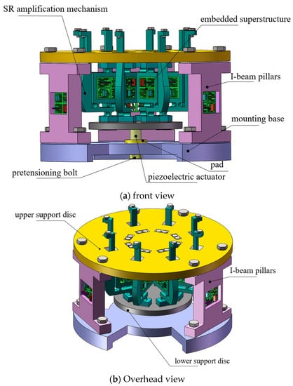
Figure 1.
Scheme diagram of the platform.
As the sensitive load requires simultaneous external tensioning in eight directions around the circumference, the actuation platform is designed symmetrically, and its input is uniformly pushed by the intelligent material actuator, typically a piezoelectric actuator. To amplify and commutate the input displacement of the piezoelectric actuator, a Scott–Russell compliant amplification mechanism is constructed as the core of this scheme [21]. The upper support disc locks the upper fulcrum of the SR compliant amplification mechanism into place, and the lower support disc is used to secure the input end of the SR mechanism. The integral mounting base is mounted with three symmetrically arranged I-beam pillars, and its upper end is used to secure the upper support plate. The pretension bolt both dynamically adjusts the preload force of the piezoelectric actuator and makes contact with the actuator via the pad. In realizing the micro-nanometer tensioning adjustment, the precision actuation is achieved via the modified SR amplification mechanism, which drives the sensitive load at the end of the SR mounting point. To mount the embedded resonant superstructure, which can be used to achieve desired fixed-frequency vibration suppression of external disturbances in particular frequency bands and is described in Section 3, the mounting rectangular slots have been positioned on the eight modified SR mechanisms as well as the three pillars. The overall plan incorporates the embedded superstructure and makes maximum use of the design space to achieve the objectives of precise actuation adjustment and natural frequency vibration reduction.
2.2. Optimization of Main Structure Parameters
It is crucial to enhance performance indicators, such as the output displacement and natural frequency of the modified SR flexible amplification mechanism, because the primary platform must accomplish a specific operating range and bandwidth. The scheme adopts a unified parameter design for each flexible hinge and initially selects three parameters to be optimized, as shown in Figure 2a, which also illustrates the operation mechanism as follows: the length of the output end beam of the SR mechanism is x1, the radius of the arc profile of the flexible hinge is x2, and the width of the input end beam is x3. In Figure 2b, din is the input displacement, dout1 is the displacement after primary amplification, and dout2 is the displacement after secondary amplification. The improved Scott–Russell mechanism is equivalent to a series of lever and Scott–Russell mechanisms. In engineering applications, the magnification ratio of the entire compliant tensioning platform is mainly determined by the motion characteristics of Scott–Russell mechanisms via the velocity projection theorem. The total platform amplification ratio can be simply estimated as the product of the Scott–Russell mechanism and the lever mechanism amplification ratio: .
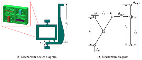
Figure 2.
The key parameters of the SR compliant and operation mechanisms.
Overall, the three factors x1, x2, x3 have little impact on the platform’s basic structure; since they are not dependent on one another, a sensitivity analysis can be carried out. The starting value of the selected optimal size is defined by the size that, at the time of preliminary design, can achieve the performance of the entire flexible tensioning platform. As a result, the selected size range of the platform is mainly determined by the actual operation of the flexible tensioning platform. As can be observed from previous studies, the first-order natural frequency Yp and amplification ratio Yt of the flexible tension platform are chosen as the results of sensitivity analysis so that the larger motion output range and higher working frequency band are fulfilled. ANSYS software was used to generate 16 sets of orthogonal experimental parameters, followed by sensitivity analyses to obtain analysis results under different combinations; the specific values are shown in Table 1. Figure 3 shows the histogram of the effects of these three structural parameters on both the amplification ratio and the intrinsic frequency of the platform. It is evident that x3 has a smaller effect on the overall platform performance compared to x1 and x2. In addition, x1 shows a positive correlation with the deformation of the platform and a negative correlation with the frequency of the platform, while x2 has the opposite effect.

Table 1.
Results of platform sensitivity analysis.
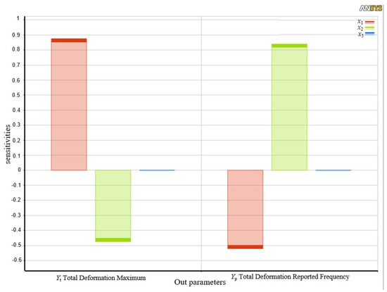
Figure 3.
Sensitivity parameter influence relationships.
Given that the derivation of the theoretical model based on the principal structure is relatively complicated, the mapping model construction of the output performance, inherent frequency, and the three response surface method parameters [22] are adopted for optimizing the main structure with regard to multiple engineering objectives. After the orthogonal experiment, the regress function from MATLAB is used to fit the simulation results, and the mapping model of amplification ratio Yt and first-order natural frequency Yp with the three parameters is obtained [23]:
Based on the above model, fitted response surfaces to deformation and intrinsic frequency are obtained as shown in Figure 4 and Figure 5, respectively. The x1 and x2 parameters have a significant influence on the platform performance. The larger the x1 and the smaller the x2, the larger the amplification ratio of the tensioning platform. The smaller the x1 and the larger the x2, the greater the natural frequency of the tensioning platform. It is evident that the theoretical model fits well and better reflects the mapping relationship between relevant parameters and platform performance indicators.
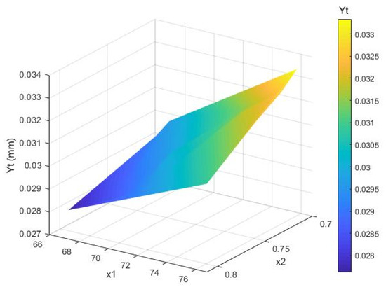
Figure 4.
The deformation fitted response surface.
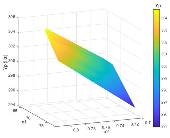
Figure 5.
The frequency fitted response surface.
The following multi-objective optimization approach is proposed to balance the amplification ratio and natural frequency to obtain optimal performance characteristics. In addition, the constraints on the size parameters take into account the limitations of the actual processing of the flexible platform as well as the requirements of the overall envelope size.
where a and b are weighted correction factors, respectively, which sum to 1. Then, using the fmincon function [24] the optimization results are corrected and rounded, and the key structural parameters are x1 = 75, x2 = 0.8, and x3 = 4.5, respectively. The amplification ratio of the scheme is close to 3.4. The first-order solid frequency reached 365 Hz, compared with the finite element simulation results (as shown in Figure 6 and Figure 7), and basically remained the same. This demonstrates the effectiveness of the optimization method; therefore, the presented scheme provides a basis for avoiding external disturbances in critical low- and medium-frequency bands. Subsequently, as shown in Figure 8, the prototype is manufactured and assembled according to the above optimization results.
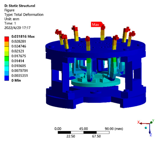
Figure 6.
The displacement nephogram of the platform.
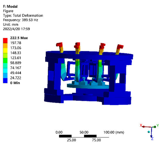
Figure 7.
The stress nephogram of the platform.
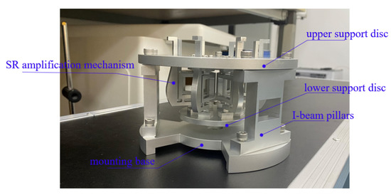
Figure 8.
Prototype of the main platform.
3. Vibration Suppression Mechanism of the Embedded Superstructure
3.1. Equivalent Dynamic Modeling
There are four major sources of vibration interference in the low-frequency region, which typically exhibits the harmonic disturbance type of interference, given that the target sensitive load is running on-orbit. Therefore, in this paper, an embedded four-phase superstructure scheme, as shown in Figure 9, is proposed for these four typical low-frequency operation disturbances.
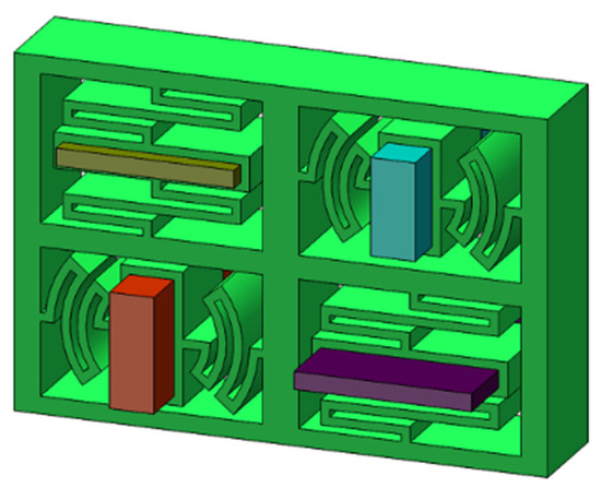
Figure 9.
The proposed embedded superstructure scheme.
The equivalent vibration suppression model of the proposed scheme is simplified in accordance with the principle of local resonance; this allows further investigation of the impact of important structural characteristics of superstructure cells on the vibration suppression effect [25]. The equivalent model is shown in Figure 10. The main structure is subjected to an external harmonic perturbation F(t) to produce a response x0, where m0, k0, and c0 represent the mass, stiffness, and damping of the main structure, respectively. xi (I = 1, …, 4), mi (I = 1, …, 4), ki (I = 1, …, 4), and ci (I = 1, …, 4) represent the displacement, mass, stiffness, and damping of each phase of the superstructure, respectively.
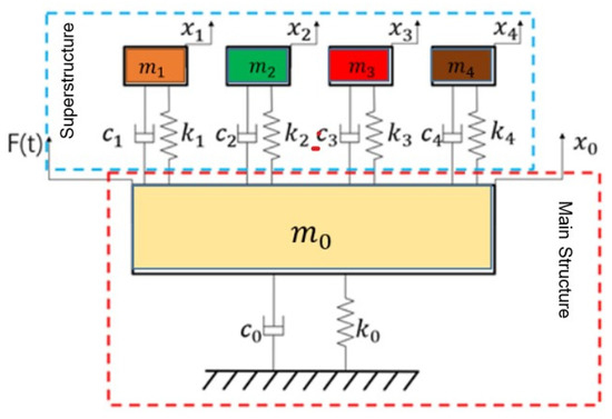
Figure 10.
The equivalent vibration suppression model.
The dynamic equations of the system are established using the Newton–Euler method as:
where ; ;
Performing the Lasse transform on the above equation shows that the frequency response function transfer matrix of the overall system is:
The first term of this matrix is chosen as the primary system’s frequency response function in order to study how the four-phase superstructure affects the vibration transfer characteristics of the main system:
where the relevant parameters are set to:
The amplitude-frequency response of the main structure is mainly affected by the mass ratio , damping ratio and natural frequency of the superstructure element.
3.2. Vibration Suppression Mechanism
In MATLAB, the controlled variable approach is used to study the influence of the major parameters of the superstructure on the vibration characteristics of the main system. Order, and , where ms is the superstructure’s overall mass. With other parameters unchanged, different mass ratios are selected to assess the influence of different mass ratios on vibration characteristics of the main system. The results are shown in Figure 11.
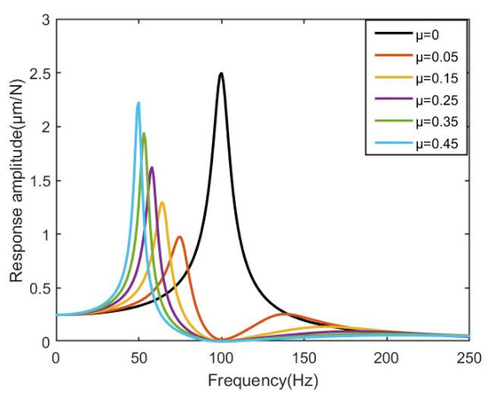
Figure 11.
The frequency response with different mass ratio of superstructure.
Studying the above trend shows that indicates the main system response in the absence of superstructure. Compared with the main system without superstructure, when the formant of the main system is greatly attenuated, the vibration is suppressed, and a new resonance peak is formed on the left side. As the mass ratio increases, the weakening amplitude of the main system increases, which demonstrates that while the vibration suppression ability is enhanced, the amplitude at the new natural frequency becomes gradually larger. Therefore, when designing the superstructure, the mass ratio of the superstructure should be considered comprehensively in order to balance its vibration suppression ability.
Then, the influence of the superstructure and the natural frequency ratio of the main system on the vibration characteristics is explored. The simulation results shown in Figure 12 are obtained. φ represents the ratio of the natural frequency of each unit of the superstructure to the natural frequency of the main structure. When the intrinsic frequency ratio is between 0 and 1, the resonance peak amplitude of the main structure decays as the frequency ratio increases, but the amplitude corresponding to the new natural frequency gradually increases. When the frequency ratio is greater than 1, the main structure’s formant attenuation remains largely unchanged with the increase in the frequency ratio, but the new fixed frequency’s amplitude increases on the left side while that on the right side gradually decreases. This demonstrates that, when the fixed frequency of the superstructure unit and the main structure are the same, the main structure’s ability to dampen vibrations depends on how much vibration interference energy it can absorb from the environment.
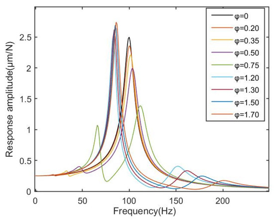
Figure 12.
The frequency response with different natural frequency ratios of superstructure to main structure.
Finally, the effect of the relative damping coefficient of the superstructure on the vibration transmission characteristics of the main structure is studied; the simulation results are shown in Figure 13. The primary structure’s attenuation amplitude increases as the relative damping ratio decreases, while additional natural frequencies start to emerge on the left and right sides of the original natural frequency. With the increase of the relative damping ratio, the attenuation amplitude of the resonance peak of the main structure decreases, indicating that the appropriate damping ratio is crucial to the main structure damping, and that the appropriate damping ratio should be selected according to different material properties in the future so as to enhance the vibration suppression effect. Therefore, based on the above conclusions, four-phase superstructure schemes with different natural frequencies of 35 Hz, 45 Hz, 55 Hz and 65 Hz are designed for typical low-frequency harmonic disturbances. The prototype can be 3D printed at a later stage to fabricate the external frame using TPU material [26] and the matching lead block injected by inlay to achieve the local resonance function. Considering the symmetry of the overall scheme, after embedding the superstructure a modal analysis of the single branch is carried out in order to reduce the simulation calculations. The first four orders of mode shape are shown in Figure 14. The findings demonstrate that the first four orders of inherent frequencies, 34.6 Hz, 44.4 Hz, 57.1 Hz, and 65.7 Hz, respectively, correspond to the local resonance of each phase of the four-phase superstructure and are essentially consistent with expectations. As a result, the simulation offers the foundation for vibration suppression.
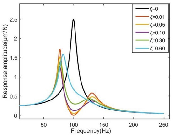
Figure 13.
The frequency response with different damping ratios of superstructure to main structure.
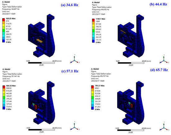
Figure 14.
The mode shapes of the single system.
4. Numerical Research and Result Analysis
This section will use the finite element method to simulate the tensioning function of the platform and the vibration suppression effect on the common harmonic disturbance in accordance with the desired function of the compliant platform [27].
4.1. Static Performance
After integrating the superstructure, the different output displacement excitation of the smart material actuator is simulated and applied to the lower support disc’s bottom surface in order to evaluate the overall platform’s static performance. Static analysis is then used to determine the platform’s input-output response results. The results are shown in Figure 15. The simulation amplification ratio is 3.2, slightly smaller than the theoretical value. The reason may be that the transverse deformation of the flexure hinges causes a reduction in output displacement.
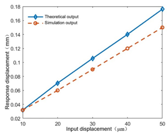
Figure 15.
Tensioning platform displacement response results.
4.2. Dynamic Tensioning Performance
The lower support disc’s bottom surface is exposed to sinusoidal displacement signals of varying amplitudes at a maximum operating frequency of 10 Hz in order to simulate the output displacement excitation of the piezoelectric actuator. This allows for evaluation of the tensioning output performance of the platform under certain input displacements by transient dynamics simulation [28]. During the simulation, the input displacement amplitude was set to several segments between 10 μm and 100 μm. The simulation time is set to 0.5 s, and the dynamic simulation results are shown in Figure 16.
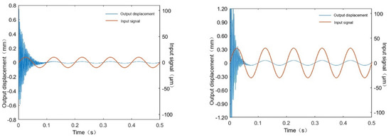

Figure 16.
Output response of the actuation platform. (a) Output response at an input displacement amplitude of 10 μm. (b) Output response at an input displacement amplitude of 30 μm. (c) Output response at an input displacement amplitude of 50 μm. (d) Output response at an input displacement amplitude of 100 μm.
Analyzing the above results, under the maximum operating frequency of 10 Hz and different amplitudes of excitation, the output displacement of the platform reaches 31 μm, 92 μm, 148 μm, 310 μm, respectively, and the output response amplitudes essentially conform to the 3 times amplification ratio. Meanwhile, from the simulation time domain curve it is evident that there is transient oscillation when the platform is initially excited; however, due to the existence of structural damping, within one cycle the oscillation gradually disappears and the platform reaches steady state. Meanwhile, the output matches the input sinusoidal signal well, which demonstrates that the platform can achieve the expected tension adjustment function.
4.3. Harmonic Response Tests of the Overall Platform
Harmonic disturbances with an amplitude of 10 m and a frequency ranging from 0 to 200 Hz are applied to the mounting base in order to examine the vibration suppression capabilities of the platforms with and without an embedded superstructure in the entire interference band. Then, harmonic response simulations are carried out; the vibration response curves are drawn in Figure 17. When compared with the platform without superstructure, it is obvious that the vibration suppression band gap is generated around the corresponding natural frequencies of the superstructure. When the external vibration is excited to the mounting base, the local resonance of the superstructure is generated. The vibration energy near the corresponding frequency is absorbed by the superstructure in the form of resonance, thus achieving the shielding and suppression of the corresponding vibration. The vibration with the corresponding frequency cannot pass through the band gap; in other words, the corresponding vibration has no impact on the main structure of the platform. Furthermore, according to the extracted displacement nephogram and stress nephogram of harmonic response shown in Figure 18, it is clear that external vibration causes local resonance of the embedded superstructure and results in obvious deformation, which conforms to the vibration reduction mechanism of the embedded superstructure.
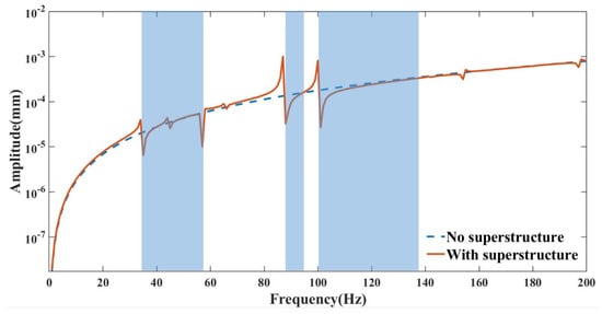
Figure 17.
The harmonic response of the platform embedded with the optimized superstructure.
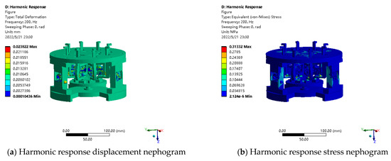
Figure 18.
Platform harmonic response results.
4.4. Vibration Suppression Tests under Fixed Frequencies Disturbance
A typical interference source is applied to the bottom of the mounting base in order to conduct a comparison study with or without the embedded superstructure to analyze the platform’s performance in terms of vibration suppression under the desired fixed frequency. Since the main purpose of the designed four-phase superstructure is to achieve vibration suppression from external harmonic disturbances at the fixed operating frequency, the typical interference source can be set to
where fi (i = 1, …, 4) is the corresponding resonant frequency of each phase of the superstructure, which can be determined via the previously mentioned modal simulation results. Ai (i = 1, …, 4) is the equivalent vibration amplitude, respectively, and can be set to 0.1 mm, 0.05 mm, 0.01 mm and 0.005 mm. After transient dynamic analysis [29], the simulation results in the time and frequency domains are processed using MATLAB, as plotted in Figure 19.
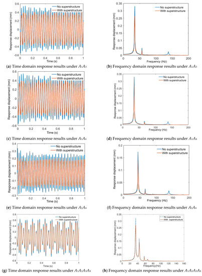
Figure 19.
The vibration suppression performance of the platform.
From Figure 19a,b, it is evident that the platform has a significant vibration suppression effect on the harmonic disturbances with frequencies of f1 and f3, and the amplitude is significantly reduced. Similarly, from Figure 19c,d, it is evident that the platform has a significant vibration suppression effect on the harmonic disturbances with frequencies of f1 and f4, and the amplitude is significantly reduced. Finally, from Figure 19g,h, it is evident that the platform also shows a significant vibration suppression effect for harmonic disturbances with frequencies of f1, f2, f3 and f4. The frequency domain results in Figure 19h show that four resonance peaks corresponding to the four excitation frequencies appear, and the amplitudes of these resonance peaks are obviously weakened, which demonstrates that the designed four-phase superstructure suppresses the vibration with desired frequency through local resonance function. The vibration suppression effects are further collated and listed in Table 2. It is evident that the vibration corresponding to the inherent frequency of each phase is suppressed to a certain extent, that the maximum vibration suppression effect appears at the first phase, and that the vibration suppression effect reaches −1.705 dB. Overall, although the designed superstructure achieves a certain vibration suppression capability, the suppression effect is limited. Because each branch of the planned superstructure does not form an array, only one single cell is used to perform vibration suppression, which has a restricted impact. Combined with the vibration suppression mechanism, future research should focus on the design of multiple embedded arrays in each branch, so as to improve the vibration suppression performance of the overall platform.

Table 2.
The vibration suppression effects.
5. Conclusions
In this study, a compliant operating platform based on an embedded superstructure and piezoelectric actuators is proposed for dealing with ultra-precision tensioning driving and vibration suppression for on-orbit sensitive loads. The main structure of the scheme is optimized based on the response surface method. Based on the local resonance mechanism, a four-phase superstructure scheme is suggested for disturbances with natural frequencies. An equivalent vibration suppression model is established, and the evolution law between these key parameters and the vibration suppression performance is studied. Finally, the tensioning output performance and the vibration suppression performance of the platform under fixed frequencies is studied using finite element analysis. The findings demonstrate that the designed platform has effective tensioning output and vibration suppression abilities. However, the insufficient vibration suppression effect also suggests that in the future embedded superstructure cells need to be arranged in arrays to improve the vibration suppression effect.
Author Contributions
Conceptualization, X.S. and J.W.; methodology, X.S., J.W. and Z.Y.; software, J.W. and Z.Y.; validation, X.S., J.W. and X.H.; formal analysis, Z.Y. and Y.Y.; investigation, X.S.; resources, X.S.; data curation, J.W. and Z.Y.; writing—original draft preparation, X.S. and J.W.; writing—review and editing, X.S. and Z.Y.; visualization, J.W.; supervision, X.S.; project administration, X.S.; funding acquisition, X.S. All authors have read and agreed to the published version of the manuscript.
Funding
The authors would like to thank the handling editor and anonymous reviewers for their useful comments and constructive suggestions. This research was supported by National Natural Science Foundation of China (No. 51905087), the Research Project of State Key Laboratory of Mechanical System and Vibration (MSV202317), the Research Funds of National Innovation Center of Advanced Dyeing & Finishing Technology (2022GCJJ11), and the Fundamental Research Funds for the Central Universities (2232023D-16).
Data Availability Statement
The data that support the findings of this study are available on request from the corresponding author, upon reasonable request.
Conflicts of Interest
The authors declare no conflict of interest.
References
- Qiu, Z.; Zhu, X. Vibration modal characteristics analysis of compliant mechanism with opening. Aerosp. Control. Appl. 2022, 48, 1–11. [Google Scholar]
- Feng, X.; Tang, L.; Guan, X.; Hao, R.; Zhang, K. Active damping and relative position control for large antenna. Aerosp. Control. Appl. 2022, 48, 17–26. [Google Scholar]
- Song, Y.; Zhang, C.; Li, Z.; Li, Y.; Lian, J.; Shi, Q.; Yan, B. Study on dynamic characteristics of bio-inspired vibration isolation platform. J. Vib. Control. 2022, 28, 1470–1485. [Google Scholar] [CrossRef]
- Zhai, M.; Zhang, B.; Li, X.; Long, Z. Design and Implementation of Permanent and Electromagnet Composite Vibration Isolation System Based on Negative Stiffness Theory. Actuators 2023, 12, 44. [Google Scholar] [CrossRef]
- Xu, C.; Xu, Z.-D.; Huang, X.-H.; Xu, Y.-S.; Ge, T. Modeling and analysis of a viscoelastic micro-vibration isolation and mitigation platform for spacecraft. J. Vib. Control. 2018, 24, 4337–4352. [Google Scholar] [CrossRef]
- Song, H.; Shan, X.; Hou, W.; Wang, C.; Sun, K.; Xie, T. A novel piezoelectric-based active-passive vibration isolator for low-frequency vibration sys-tem and experimental analysis of vibration isolation performance. Energy 2023, 278, 127870. [Google Scholar] [CrossRef]
- Niu, M.; Chen, L. Analysis of a bio-inspired vibration isolator with a compliant limb-like structure. Mech. Syst. Signal Process. 2022, 179, 109348. [Google Scholar] [CrossRef]
- Wang, X.; Wang, D.; Li, F.; Zhang, Y.; Xu, Z.; Wang, T.; Fu, G.; Lu, C. Self-learning vibration absorber with negative electromagnetic stiffness for variable vibration. Int. J. Mech. Sci. 2023, 248, 108225. [Google Scholar] [CrossRef]
- Clark, L.; Shirinzadeh, B.; Zhong, Y.; Tian, Y.; Zhang, D. Design and analysis of a compact flexure-based precision pure rotation stage without actuator redundancy. Mech. Mach. Theory 2016, 105, 129–144. [Google Scholar] [CrossRef]
- Sun, X.; Wang, Z.; Yang, Y. Design and Experimental Investigation of a Novel Compliant Positioning Stage with Low-frequency Vibration Isolation Capability. Sens. Actuators A Phys. 2019, 295, 439–449. [Google Scholar] [CrossRef]
- Yang, X.; Wu, H.; Li, Y.; Chen, B. Dynamic Isotropic Design and Decentralized Active Control of a Six-axis Vibration Isolator via Stewart Platform. Mech. Mach. Theory 2017, 117, 244–252. [Google Scholar] [CrossRef]
- Herpe, X.; Walker, R.; Dunnigan, M.; Kong, X. On a simplified nonlinear analytical model for the characterisation and design opti-misation of a compliant XY micro-motion stage. Robot. Comput.-Integr. Manuf. 2018, 49, 66–76. [Google Scholar] [CrossRef]
- Sun, X.; Hu, W.; Bai, Z.; Yang, Y. Experimental investigation on a new sensitive payload platform with simultaneous positioning and vibration suppression capabilities. J. Vib. Control. 2022, 28, 1200–1213. [Google Scholar] [CrossRef]
- Ciani, G.; Arain, M.A.; Aston, S.M.; Feldbaum, D.; Fulda, P.; Gleason, J.; Heintze, M.; Martin, R.M.; Mueller, C.L.; Kumar, D.M.N. Small optic suspensions for advanced LIGO input optics and other precision optical ex-periments. Rev. Sci. Instrum. 2016, 87, 114504. [Google Scholar] [CrossRef] [PubMed]
- Yi, S.; Zhang, Q.; Sun, X.; Yang, B.; Meng, G. Simultaneous micropositioning and microvibration control of a magnetostrictive Stewart plat-form with synthesized strategy. Mech. Syst. Signal Process. 2023, 187, 109925. [Google Scholar] [CrossRef]
- Yu, X.; Zhou, J.; Liang, H.; Jiang, Z.; Wu, L. Mechanical metamaterials associated with stiffness, rigidity and compressibility: A brief review. Prog. Mater. Sci. 2018, 94, 114–173. [Google Scholar] [CrossRef]
- Zhuoqun, W.; Pengfei, W.; Yan, Z.; Jiang, Y. Vibration reduction technology of mechanical metamaterials presented to large scale structures. Acta Aeronaut. Et Astronaut. Sin. 2018, 39, 721651. [Google Scholar]
- Jin, Y.; Shi, Y.; Yu, G.-C.; Wei, G.-T.; Hu, B.; Wu, L.-Z. A multifunctional honeycomb metastructure for vibration suppression. Int. J. Mech. Sci. 2020, 188, 105964. [Google Scholar] [CrossRef]
- Fan, H.; Yang, L.; Tian, Y.; Wang, Z. Design of metastructures with quasi-zero dynamic stiffness for vibration isolation. Compos. Struct. 2020, 243, 112244. [Google Scholar] [CrossRef]
- Gao, H.; He, W.; Zhang, Y.; Sun, C. Adaptive finite-time fault-tolerant control for uncertain flexible flapping wings based on rigid finite element method. IEEE Trans. Cybern. 2021, 52, 9036–9047. [Google Scholar] [CrossRef]
- Wu, H.; Lai, L.; Zhang, L.; Zhu, L. A novel compliant XY micro-positioning stage using bridge-type displacement amplifier embed-ded with Scott-Russell mechanism. Precis. Eng. 2022, 73, 284–295. [Google Scholar] [CrossRef]
- Lu, C.; Feng, Y.W.; Liem, R.P.; Fei, C.W. Improved Kriging with extremum response surface method for structural dynamic reliability and sensitivity analyses. Aerosp. Sci. Technol. 2018, 76, 164–175. [Google Scholar] [CrossRef]
- Wu, Z.; Wang, S.; Zhang, Y.; Song, J.; Xue, B. Optimization of Process Parameters for Laser Cutting of AZ31B Magnesium Alloy Based on Orthogonal Experiment and BP Neural Network. Trans. Indian Inst. Met. 2023. [Google Scholar] [CrossRef]
- Le Luong, H.T.; Messine, F.; Henaux, C.; Mariani, G.B.; Voyer, N.; Mollov, S. Comparison between fmincon and NOMAD optimization codes to design wound rotor synchronous machines. Int. J. Appl. Electromagn. Mech. 2019, 60, S87–S100. [Google Scholar] [CrossRef]
- Li, Z. Research on design and experiment of a XY-Decoupled compliant mechanism with high modal damping using embedded local resonance metastructure. S. China Univ. Technol. 2020. [Google Scholar] [CrossRef]
- Zu, R.; Fan, Q.; Chen, Y.; Chen, W.; Li, H.; Liu, H. Research progress and application of 3D Printing TPU materials. Mod. Chem. Res. 2023, 130, 20–24. [Google Scholar] [CrossRef]
- Khushnood, M.A.; Wang, X.; Cui, N. Active vibration control of a slewing spacecraft’s panel using H∞ control. J. Vi-Broengineering 2016, 18, 2959–2973. [Google Scholar] [CrossRef]
- Harada, K.; Kinoshita, T.; Shiratori, N. The emergence of controllable transient behavior using an agent diversification strategy. IEEE Trans. Syst. Man, Cybern.-Part A Syst. Hum. 2003, 33, 589–596. [Google Scholar] [CrossRef]
- Wang, Z.; Yin, B.; Yan, H. Weak Signal Detection Based on Pseudo Wigner Ville Distribution. In Journal of Physics: Conference Series; IOP Publishing: Bristol, UK, 2019; Volume 1176, p. 062040. [Google Scholar]
Disclaimer/Publisher’s Note: The statements, opinions and data contained in all publications are solely those of the individual author(s) and contributor(s) and not of MDPI and/or the editor(s). MDPI and/or the editor(s) disclaim responsibility for any injury to people or property resulting from any ideas, methods, instructions or products referred to in the content. |
© 2023 by the authors. Licensee MDPI, Basel, Switzerland. This article is an open access article distributed under the terms and conditions of the Creative Commons Attribution (CC BY) license (https://creativecommons.org/licenses/by/4.0/).