Abstract
A collision avoidance method that is specifically tailored for UAVs (unmanned aerial vehicles) operating in converging airspace is proposed. The method is based on ADS-B messages and it aims to detect and resolve conflicts between UAVs. The proposed method involves two main steps. First, a UAV conflict-sensing scheme is developed, which utilizes ADS-B information flow path and analyzes the message format information. Second, an unscented Kalman filter is used to predict UAV trajectories based on the acquired ADS-B information. The predicted information is then used to determine potential conflict scenarios, and different deconfliction strategies are selected accordingly. These strategies include speed regulation, direction regulation, and compound deconfliction, and are mathematically validated using the velocity obstacle method. The feasibility and effectiveness of the proposed method are evaluated through simulation, and it is concluded that the method can significantly improve the conflict resolution capability of UAV flights. This research provides a valuable contribution to the field of UAV collision avoidance, and can serve as a theoretical foundation for further advancements in this area.
1. Introduction
The impressive advancements in aviation and artificial intelligence technology have highlighted the superiority of UAVs, which have demonstrated significant potential in both civilian and military fields. In the civilian sector, UAVs are increasingly being utilized for their simple operation, strong adaptability, and cost-effectiveness in various applications such as communication relay, disaster relief, agricultural plant protection, map mapping, and terrain survey. In the military, UAVs play an increasingly important role in modern military operations due to their good concealment effect, long cruise time, and low cost of battle damage, and the tasks they perform are becoming increasingly diversified. Overall, the development of UAV technology has opened up new opportunities and challenges, and its potential in both civilian and military fields is becoming increasingly recognized. As the technology continues to advance, we can expect to see even more diverse and innovative applications of UAVs in the future. As the range of applications for UAVs continues to expand, and the frequency and quantity of their use increase, the aviation sector is facing mounting safety pressures. During flight, UAVs must not only ensure their own safety but also that of surrounding aircraft. Therefore, their ability to detect and resolve flight conflicts is essential to their overall safety. In the future, UAVs will share airspace with manned aircraft, creating more diverse uncertainties and increasing the potential for flight conflicts. To ensure the safety of UAVs in shared airspace, it is imperative to enhance their autonomy and intelligence, as well as their conflict awareness and collision avoidance capabilities.
Based on current research at both domestic and international levels, UAVs’ awareness of flight conflicts mainly relies on location information. Various methods are used to obtain UAV location information, including satellite-based positioning, automatic dependent surveillance-broadcast (ADS-B), traffic collision avoidance system (TCAS), inertial navigation, and radar detection [1].
Effective flight conflict resolution techniques are crucial to ensure the safe operation of UAVs. Research has proposed various methods for UAV conflict resolution. For instance, the study by [2] introduced a geometric optimization method that is now widely used in future air traffic management. The authors of [3] investigated collision avoidance methods for dynamic obstacles and proposed using guide laws for UAV conflict resolution. The research by [4] proposed a two-aircraft deconfliction strategy based on the geometric optimization method. Ref. [5] improved the artificial potential field method to avoid local minimums and unreachable path target points. The authors of [6] proposed a potential field-ant-colony algorithm-based trajectory-planning method that used information between the environment and the target to construct heuristic factors. The study by [7] improved obstacle avoidance path planning efficiency by constructing a new potential function. The research by [8] proposed a membrane evolution artificial potential field method for path planning in both static and dynamic environments. Ref. [9] proposed a hybrid algorithm combining artificial potential field and ant colony algorithms to solve the multi-aircraft flight conflict problem in complex low-altitude environments. Finally, the authors of [10] combined genetic algorithms to obtain the optimal route by changing the heading and speed, effectively solving the flight conflict problem among aircraft in free flight.
Most of the flight conflict resolution methods mentioned above are designed to tackle flight conflicts that arise during flight. However, potential flight conflicts in non-linear environments are difficult to detect, posing a threat to flight safety. Unscented Kalman filter (UKF) is a nonlinear filtering method that can estimate the system state by observing current data without the need for an accurate model of the system. UKF has been widely applied in various fields such as power system dynamic state estimation [11], electric vehicle state parameter estimation [12], lithium ion power battery state estimation [13], target tracking [14], and signal processing [15].
2. Flight Conflict Perception and Prediction
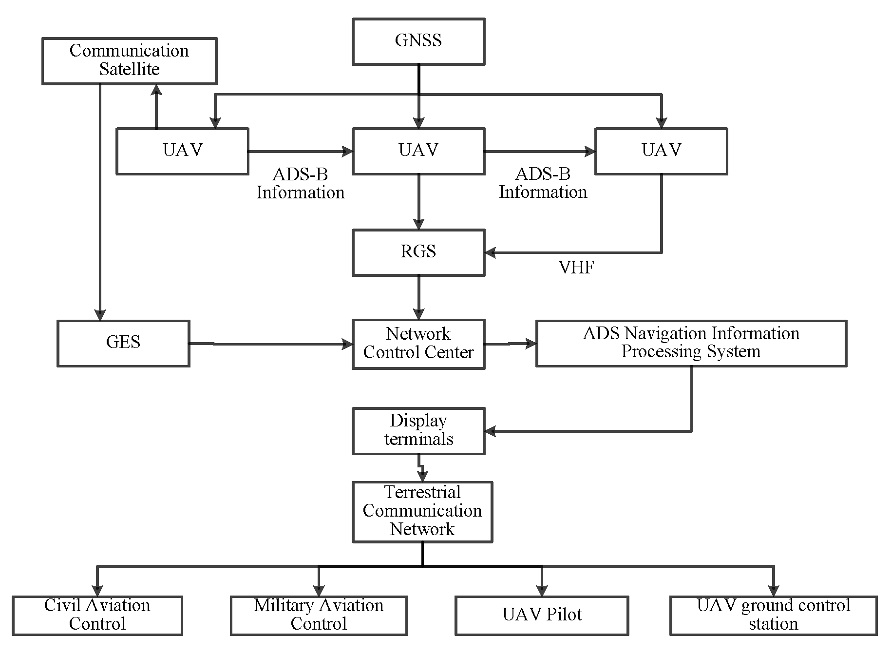
2.1. ADS-B Technology
ADS-B is a comprehensive surveillance technology that includes automatic dependent surveillance (ADS), traffic collision avoidance system (TCAS), and field surveillance technology, and it is expected to be one of the primary surveillance methods in the new navigation system program of the International Civil Aviation Organization (ICAO) in the future [16]. The ADS-B system broadcasts information, such as the aircraft’s latitude, longitude, altitude, speed, and secondary radar transponder code information, which can provide important data for predicting potential flight conflicts involving UAVs [17].
The UAV flight conflict awareness program starts with the UAV acquiring its own position information and transmitting it to the airborne flight management computer to form ADS-B information. This information is then distributed through the ADS-B system, continuously received and exchanged to locate the aircraft’s position, and provide the UAV with an awareness of the surrounding flight situation. The UAV sends its status parameters to the communication satellite or remote ground station (RGS) via the aircraft Earth station (AES) or aircraft communications addressing and reporting system (ACARS). The data are then visualized and displayed on the control units, UAV pilots, and ground control stations for a synchronized monitoring of the UAV flight status. Using the same coordinate system and reference time, the UAV’s aviation computer solves and predicts the flight status of surrounding aircraft to discover potential conflict points in the UAV’s flight process. This enables corresponding avoidance measures to be taken and the UAV flight conflict relief to be achieved. Figure 1 shows the UAV flight conflict perception scheme combined with the ADS-B information flow path.
Figure 1.
UAV flight conflict awareness scheme.
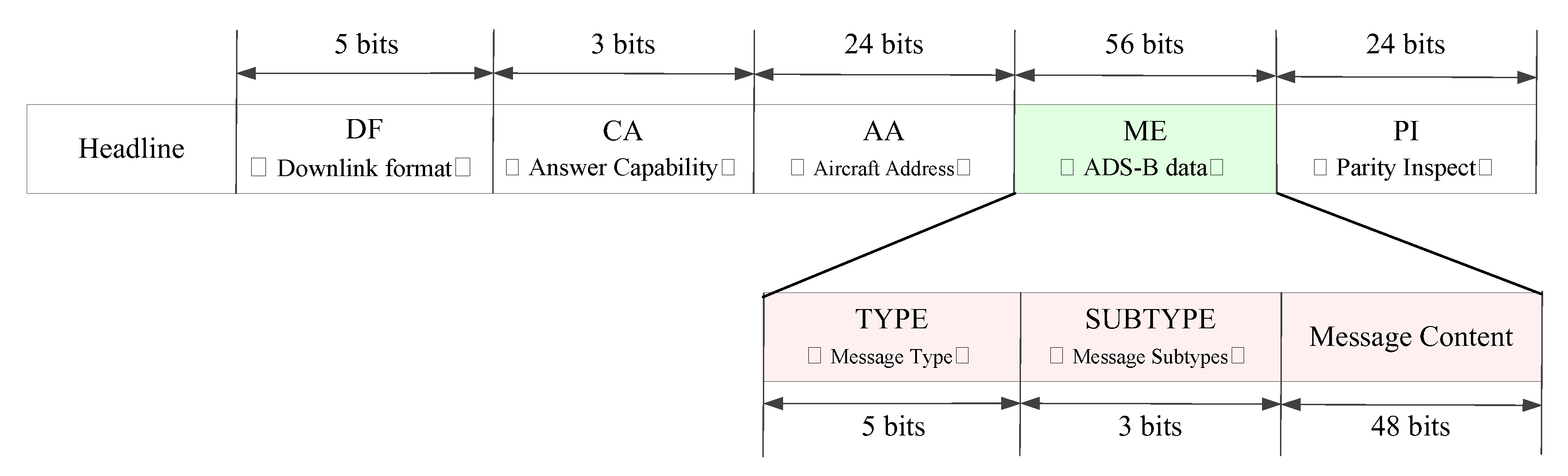
2.2. ADS-B Message Structure
The ADS-B message content is 112 bits in total and is divided into five parts comprising: ① a 5-bit downlink format (DF); ② a 3-bit answer capability (CA); ③ a 24-bit aircraft address (AA); ④ a 24-bit parity check (PI); and ⑤ 56-bit ADS-B data (ME). [18] The specific allocation amounts and functions are shown in Figure 2. The 56-bit ADS-B data are subdivided into a 5-bit message type (TYPE) field, a 3-bit message subtype (SUBTYPE) field, and a 48-bit message content. The message content is an important carrier of aircraft flight status parameters and ground target information parameters, carrying the position information, altitude information, and aircraft airspeed information of air or ground targets. In this paper, based on the UAV position information in the ME field, the flight path of the UAV is predicted.
Figure 2.
Message body.
2.3. Trajectory Prediction Based on UKF
Kalman filtering (KF) is an optimal autoregressive data processing algorithm that centers on smoothing, filtering, and predicting the input states using the state equations of the linear system and the observed information, which in turn improves the accuracy of the output measurements [19].
Extended Kalman filter (EKF) is an evolution of the KF and can be used to deal with weakly nonlinear systems. It uses an approximation to approximate a nonlinear system to a linear system using a Taylor series expansion. However, since it is an approximation of a nonlinear system, it is more demanding for a nonlinear system, and EKF works better for weakly nonlinear systems.
UKF solves the nonlinear system problem by approximating the probability distribution of the initial input of the nonlinear system by unscented transformation, which does not require linear changes to the nonlinear system equations. The motion state of the UAV is affected by a variety of nonlinear uncertainties, and its motion state is not a superposition of simple linear motion, and its flight state can be regarded as a nonlinear motion that changes continuously with time. UKF approximates the probability distribution of the initial state by a fixed number of sigma sampling points, and brings these points into the nonlinear system for solution, so as to obtain the real-time position estimation information of the UAV. UKF reduces the fluctuation of the system model due to the approximate nonlinear function, does not require linear approximation of the nonlinear system function, and does not need to deal with the complex Jacobi matrix, which reduces the system complexity and improves the stability and computational accuracy of the system output.
2.3.1. Unscented Transformation (UT)
The essence of the UT is to approximate the initial probability distribution of the nonlinear function by specific rules and brings the approximate sampled values into the nonlinear system calculation to obtain the corresponding system output. The advantage of UT is that it does not fall into computational difficulties due to the increased complexity of the system model, and the purpose is to avoid the computational difficulties for the linear approximation process and the introduction of new errors into the system model after the approximation. The UT selects some sigma sampling points that are equal to the mean and covariance of the initial inputs using specific rules, and then brings the sigma points into the nonlinear system model to solve for the corresponding output values, as well as the mean and covariance of the output values [20].
2.3.2. Main Steps of the UKF Algorithm
The specific steps of UKF for the flight track prediction process of UAV can be divided into eight steps, which are as follows:
- Step 1: Build a system state model.
It is assumed that the system state of the UAV at moment can be obtained from the system state of the UAV at moment , as shown in Equation (1):
where and are dimensional state matrices, is a dimensional initial input quantity matrix, is a dimensional process noise matrix, and , , and are all time-varying variables. In the nonlinear system model, the system equations is:
The and dimensional measurement noise matrices are brought into the observation equation to obtain the observed . The dimensional process noise matrix and the dimensional measurement noise matrix are assumed to be independent and both conform to the Gaussian distribution, i.e.,
- Step 2: Input parameters.
Assuming that the initial state expectation of the system is and the initial state covariance matrix is :
- Step 3: Use Gaussian distribution to generate sigma sampling points.
After , sigma points are constructed, and the corresponding weights are also constructed:
where is a scale factor of size . The larger is, the farther the sigma point is from the mean of the state, and vice versa. The column of the matrix square root is represented by . is the adjustment factor, which can adjust the distribution of sigma points near the mean by taking different values of . is generally taken. The smaller the value of is, the more concentrated the distribution range of sigma point is from the mean value, and the larger the value, the more dispersed it is. in this paper. Set , thus making the matrix is semi-positive definite.
- Step 4: Calculation of sigma test point weight.
The weight of the expectation of the first sigma sampling point and the weight of the variance , where is the non-negative weight coefficient containing the prior distribution, which is generally taken as when satisfies the Gaussian distribution. , where . is the mean weight of the sigma point, and is the covariance weight of the sigma point.
- Step 5: Predict the new state equation.
The sigma point set is mapped to the nonlinear state transfer equation , and then the predicted mean and predicted covariance matrices are calculated as Equations (8) and (9), respectively:
- Step 6: Measurement status update.
Based on the state prediction values obtained in the previous step, the new observations are brought into the observation equation to obtain the new observation, which is calculated as Equation (11):
The new set of sigma points are summed by assigning different weights to them and can be used to predict the estimated mean and covariance of the observations.
Observed value covariance matrix:
- Step 7: Covariance matrix of state measurements.
- Step 8: State update and covariance matrix update.
3. Flight Conflict Relief
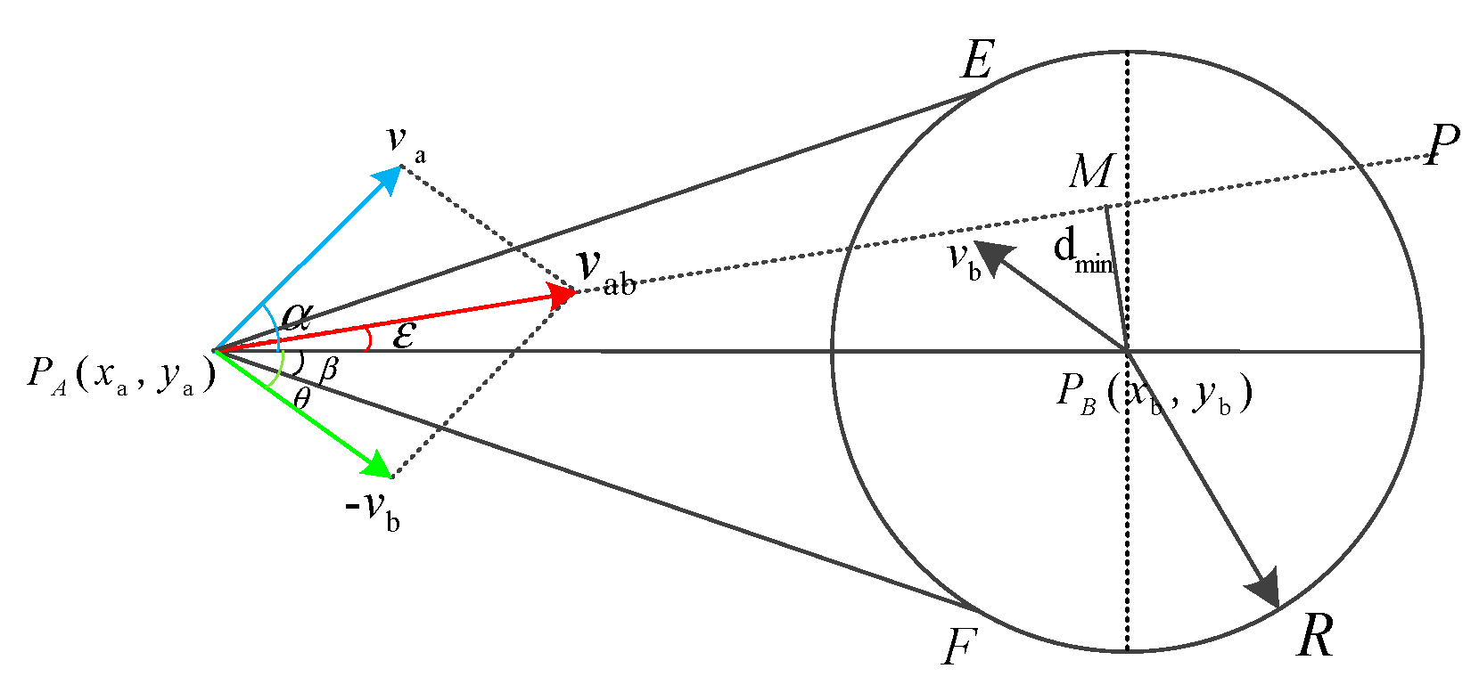
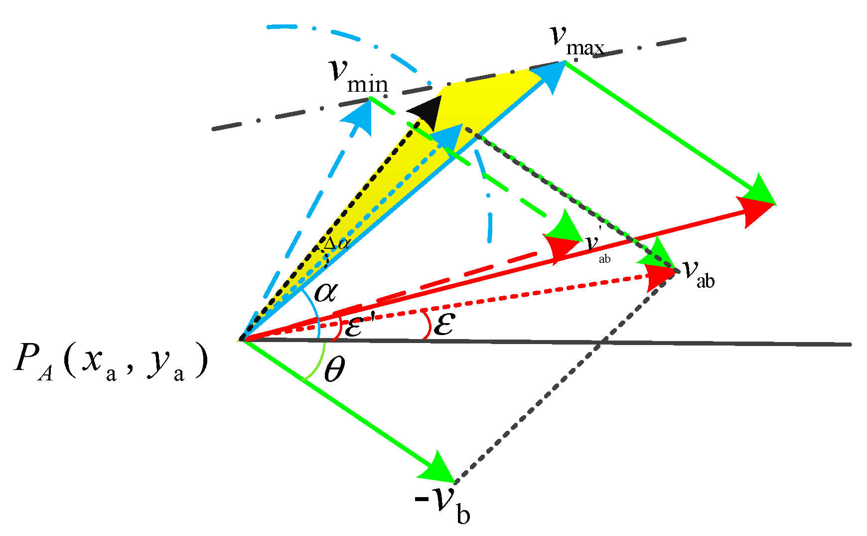
3.1. Flight Conflict Resolution Model
VO is a method of flight conflict resolution based on velocity vector, and it is relatively easy to perform flight conflict resolution at altitude if there is an altitude difference in the UAV during flight. In this paper, we mainly discuss the VO method in a two-dimensional plane, assuming that the flight conflict occurs in the same horizontal plane and the conflict resolution by altitude is not possible.
Definition 1.
, is the ray where the relative velocity is located and is the safety range of the intruder. The relative velocity is located in the ray and the non-empty set of the safety range area of the obstacle is the relative collision area.
The velocities of UAV and intruder are and , respectively, and the threat circles and are constructed with the position points of and as the centers and and as the radii, respectively, and their coordinate positions are set to and , respectively; then, the velocities of UAV and intruder are and , respectively. To facilitate the calculation, the UAV is considered as a mass point, the current position of the UAV is the origin of the coordinates, the axis is the line between the UAV and the center of the intruder, the axis is the direction of the UAV pointing to the intruder, and the normal to the axis and through the origin of the coordinates is the axis to establish a right angle coordinate system . The radius of the intruder is expanded to a circle of . The velocity barrier method model is shown in Figure 3, the relative velocity between the UAV and the intruder is , and the size of the angle between it and the axis is . and are the size of the angle between the UAV flight speed direction, the relative collision zone boundary and the axis orthogonal, respectively, and is the angle between the intruder flight speed direction and the axis.
Figure 3.
Velocity obstacle model.
Assuming that the initial distance between the UAV and the intruder is and the distance between the intruder and ray is . Combined with the geometric relationships in Figure 3, we can see that,
To determine whether there is a conflict between the UAV and the dynamic obstacle, it is only necessary to determine whether the ray where is located falls in the velocity obstacle cone, in , when , where the ray falls in the relative collision zone, at this time the UAV and the intruder there is a flight conflict, and then only need to compare the size between and can be. In the vector velocity triangle, the sine theorem shows that,
According to the trigonometric formula, it is obtained that,
From the expression, it can be seen that the magnitude of depends on the magnitude of the values of , and the angle between the two and the axis. According to Equations (18) and (21), it can be seen that when the relative speed where ray crosses the safety range area of the intruder, if UAV continues to fly according to the current speed magnitude and direction, there will be a flight conflict with the intruder, when . When , then there will be no flight conflict between the UAV and the intruder.
3.2. Flight Conflict Resolution Strategies
Combined with the actual flight scenario of UAV, it is assumed that the flight conflict resolution between UAV and intruder mainly occurs at the same altitude, i.e., the flight conflict resolution between UAV and intruder can be simplified to the flight conflict resolution in two-dimensional plane. According to the VO method, the mathematical proofs are carried out according to the velocity resolution, heading resolution and compound resolution, respectively.
3.2.1. Speed Deliverance
Speed deliverance refers to the process of conflict deconfliction, according to the coordinate position relationship between the UAV and the intruder, without changing the UAV heading angle, i.e., without changing the UAV speed direction and by increasing or decreasing the numerical size of the UAV speed, the safe distance between the UAV and the intruder is ensured to achieve conflict deconfliction. The specific deconfliction process is shown in Figure 4.
Figure 4.
Speed deliverance.
The blue dashed line in the figure indicates the velocity of the UAV after changing the numerical size of the velocity , whose angle with the axis positive is still , and the red dashed line indicates the relative velocity of the two , whose angle with the axis positive has a size of . In the velocity-adjusted vector triangle, by the sine theorem it is obtained that:
The solution is:
During the conflict resolution process, the relationship between the UAV speed adjustment amount and is given by:
Due to the flight performance of the aircraft, the speed cannot be adjusted indefinitely and has a certain speed boundary, and for some specific flight conflict scenarios, such as phase flight, it is difficult to achieve the purpose of conflict resolution by speed adjustment at this time, so the speed resolution scheme has some limitations in some scenarios.
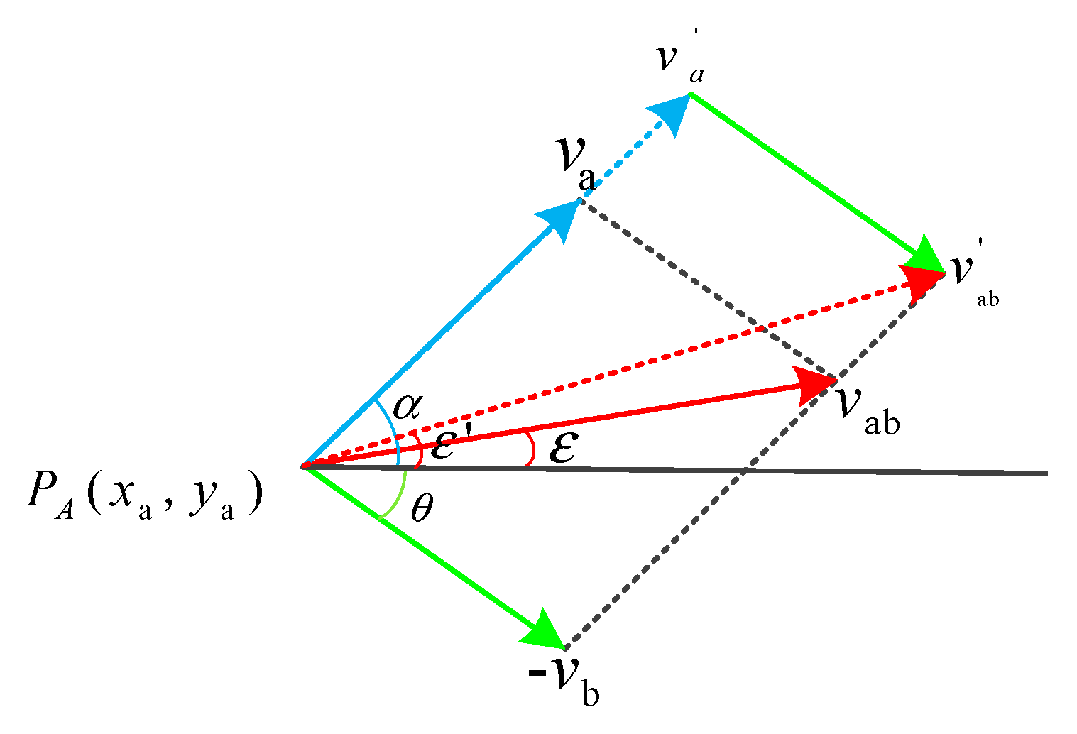
3.2.2. Heading Deliverance
Heading deliverance means that the UAV achieves conflict relief by adjusting the flight heading so that the horizontal separation between the UAV and the intruder meets the minimum safety standards. When changing the heading of the UAV, it is stipulated that only the angular magnitude of the flight speed vector is changed, i.e., the heading angle of the UAV flight, and the speed magnitude, etc., remains unchanged. The heading deconfliction scheme is shown in Figure 5.
Figure 5.
UAV of the change in speed before and after the release of the UAV’s heading.
The blue dashed line in the figure indicates the direction of the velocity of the UAV after changing its heading, and its angle with the axis positive is , and the red dashed line is the magnitude and direction of the relative velocity of the UAV after changing its heading, and its angle with the axis positive is . is known from the provisions of the heading release and the schematic diagram of the velocity change before and after the heading release, which is obtained from the sine theorem:
The solution is:
In the course of heading relief, the UAV’s heading adjustment is:
3.2.3. Compound Deliverance
Due to time and distance constraints, relying solely on heading deployment can no longer meet the collision avoidance requirements of UAVs. In order to avoid the occurrence of aerial collisions of UAVs as far as possible and allow full play to their mobility and flexibility, collision avoidance can be carried out by means of simultaneous adjustment of heading and speed. When the UAV is deployed in the compound, taking into account its maneuverability and safety performance, the adjustment amount of speed and heading is specified within a certain interval, namely:
The composite decoupling process is shown in Figure 6, assuming that the state of the intruder does not change. in the figure is the maximum deflection of the heading, and are the minimum and maximum values of the velocity, respectively, and the yellow shaded area is the set of composite decoupling solutions.
Figure 6.
UAV composite relief solution set (shaded in yellow).
After the UAV performs the composite decoupling, according to Figure 6 and Equation (21), we can obtain:
The solution is:
Considering the speed and direction indicators together, the composite decoupling process is transformed into an optimization problem with the objective function expressed as:
where, is an indicator of the amount of speed adjustment and is a heading adjustment indicator. The smaller the value of the two, the more secure and stable operation of UAV can be ensured. and are the weight values of tuning speed and direction, respectively, which are generally adjusted between according to the priority of UAV collision avoidance strategy selection, and the actual operation and are taken in this paper:
Therefore, the composite dissociation process can be transformed into an optimization problem:
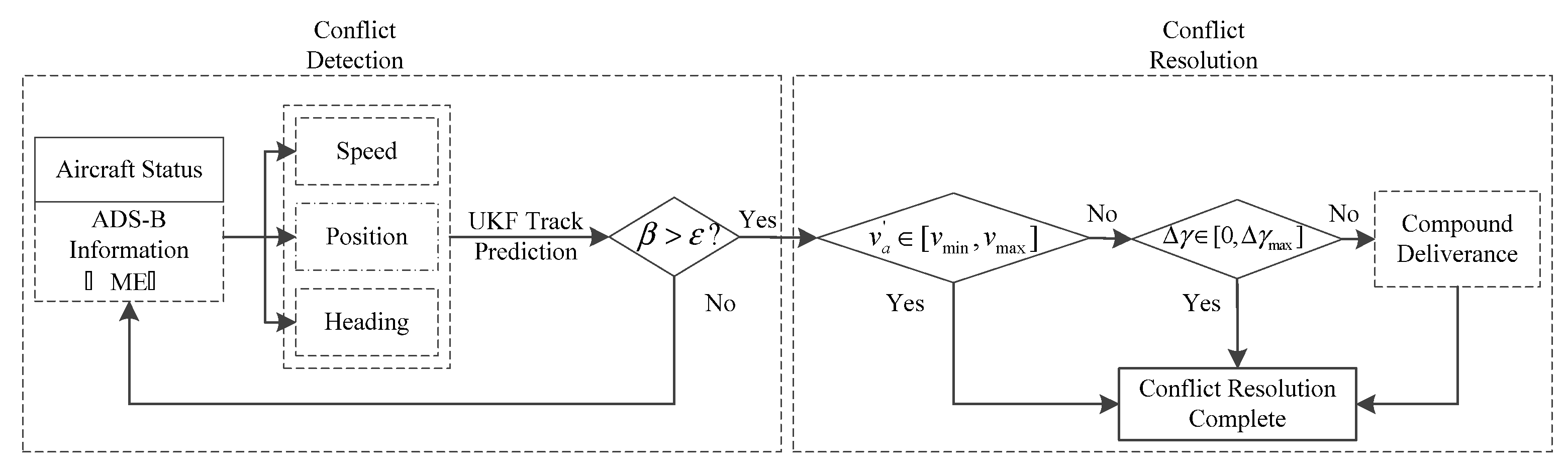
4. UAV Conflict Resolution Strategy Selection Process
In the flight process, if the UAV and the intruder are in different altitude layers, the flight conflict can be deconflicted by means of altitude adjustment, and such deconfliction is relatively simple. In this paper, we focus on the deconfliction of the same altitude level, and adopt different deconfliction strategies for different flight conflict models. Based on the principle that it is convenient for the UAV to perform the deconfliction operation, the priority is to adopt the speed adjustment deconfliction, and if the speed deconfliction cannot meet the deconfliction requirements, the heading deconfliction is adopted, and finally the compound deconfliction is adopted. After the release, the UAV flies directly to the end point and no longer performs the track recovery operation.
The flow of the UAV flight decoupling strategy is shown in Figure 7. First, based on the information provided by the ADS-B information, the UKF is used to perform the trajectory prediction, and by judging the size relationship between and , it is predicted whether a flight conflict will occur between the UAV and the intruder in the future flight process. If there is a potential flight conflict, the corresponding way of conflict resolution needs to be selected according to the conflict resolution strategy. It is determined whether the speed change amount can meet the resolution requirement and speed constraint; if not, it is judged whether the resolution requirement and heading constraint are met through the heading angle change amount. If both of these ways cannot achieve the purpose, the compound resolution is used.
Figure 7.
UAV conflict resolution process.
5. Simulation Verification
In order to verify the effectiveness of the proposed method in the paper, it is verified by Matlab2021a simulation experimental environment, and the following settings are used to predict the UAV trajectory based on the UKF and verify the effect of three conflict scenarios decoupling.
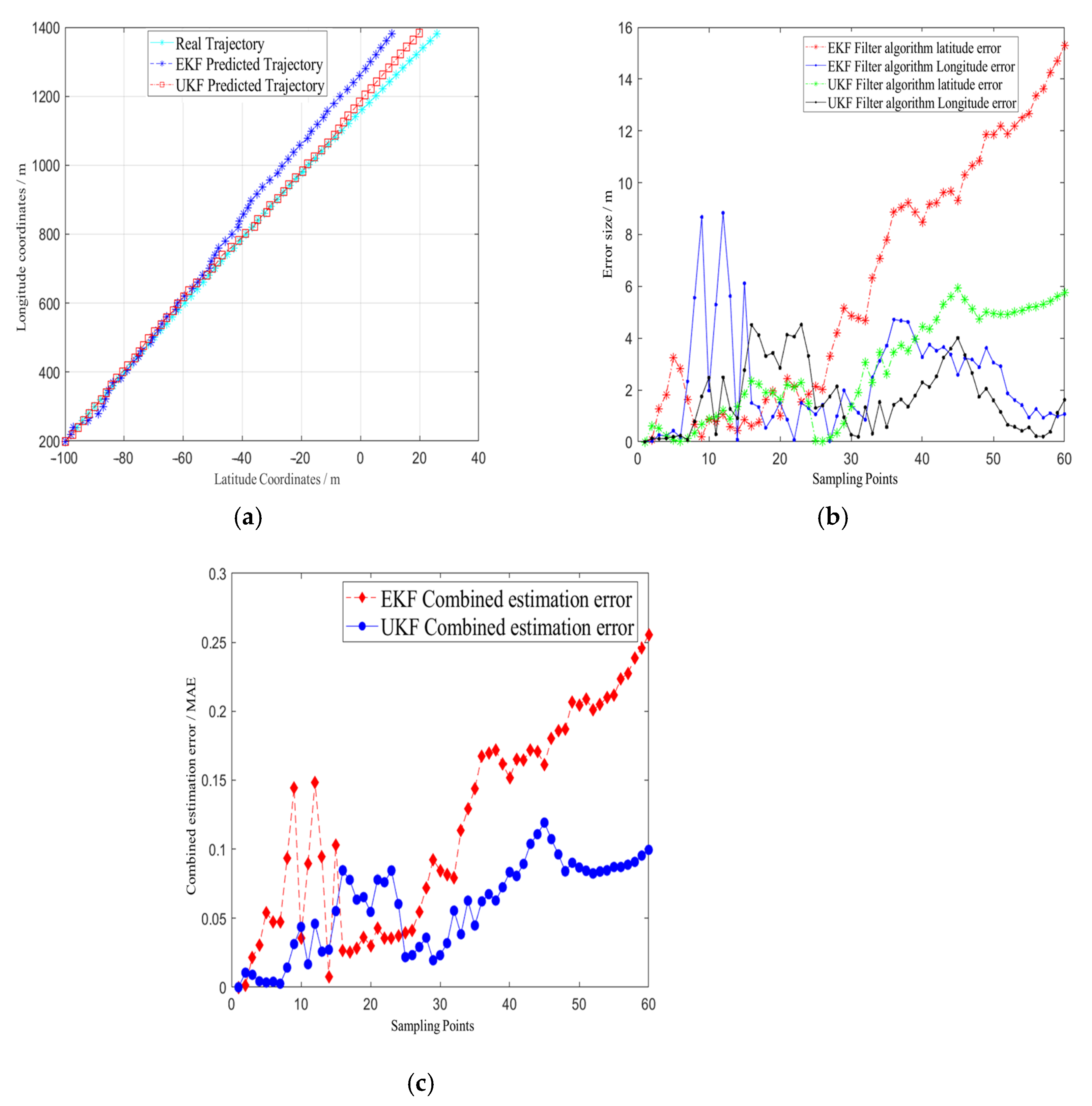
5.1. Track Prediction Verification
The position information of the UAV is obtained from the ME field of the ADS-B message, the initial position of the UAV is , the unit of measurement is the meter, the sampling time is 1 s, and a total of 60 times are sampled. The process noise and the measurement noise satisfy the non-correlation, and the mean value is Gaussian distribution. The UKF and EKF are used to predict the real UAV trajectory, respectively. The specific results are shown in Figure 8.
Figure 8.
Analysis of UKF and EKF track prediction results: (a) UKF and EKF trajectory forecast; (b) UKF and EKF latitude and longitude coordinates prediction error size; (c) combined UKF and EKF prediction errors.
Figure 8 contains three graphs, identified as (a), (b), and (c). In Figure 8a, the prediction trajectory plot of UKF and EKF is presented, and it can be observed that the prediction effect of UKF is better than that of EKF, with a better fit to the true value. Figure 8b displays the magnitude of the prediction errors of the longitude and latitude coordinates of UKF and EKF. The figure shows that the magnitude of the prediction errors of the longitude and latitude of UKF is relatively stable, while the stability of the prediction errors of the longitude and latitude of EKF is not as good as that of UKF. In Figure 8c, the prediction comprehensive error is shown, and it can be seen that the overall performance of UKF’s prediction comprehensive error is superior to EKF. The simulation data of the three charts are summarized in Table 1. The latitude error, longitude error, and comprehensive error of UKF are 46%, 72%, and 50% of EKF, respectively.
Table 1.
UKF and EKF error analysis.
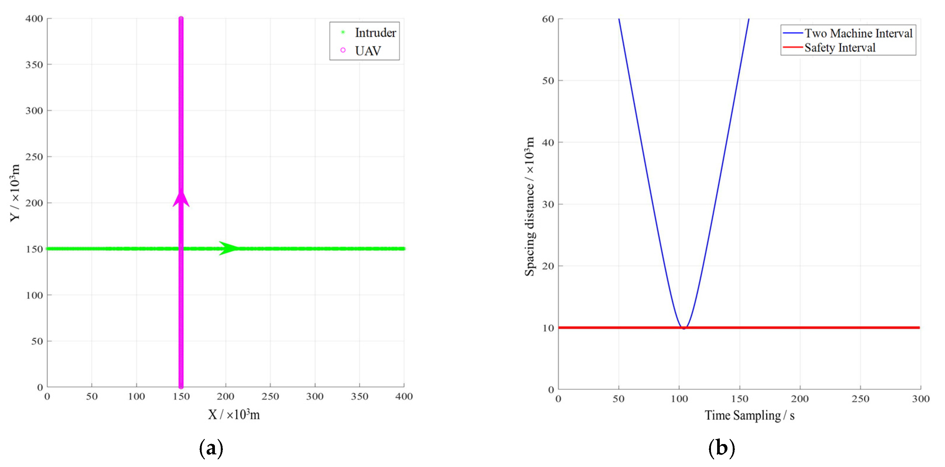
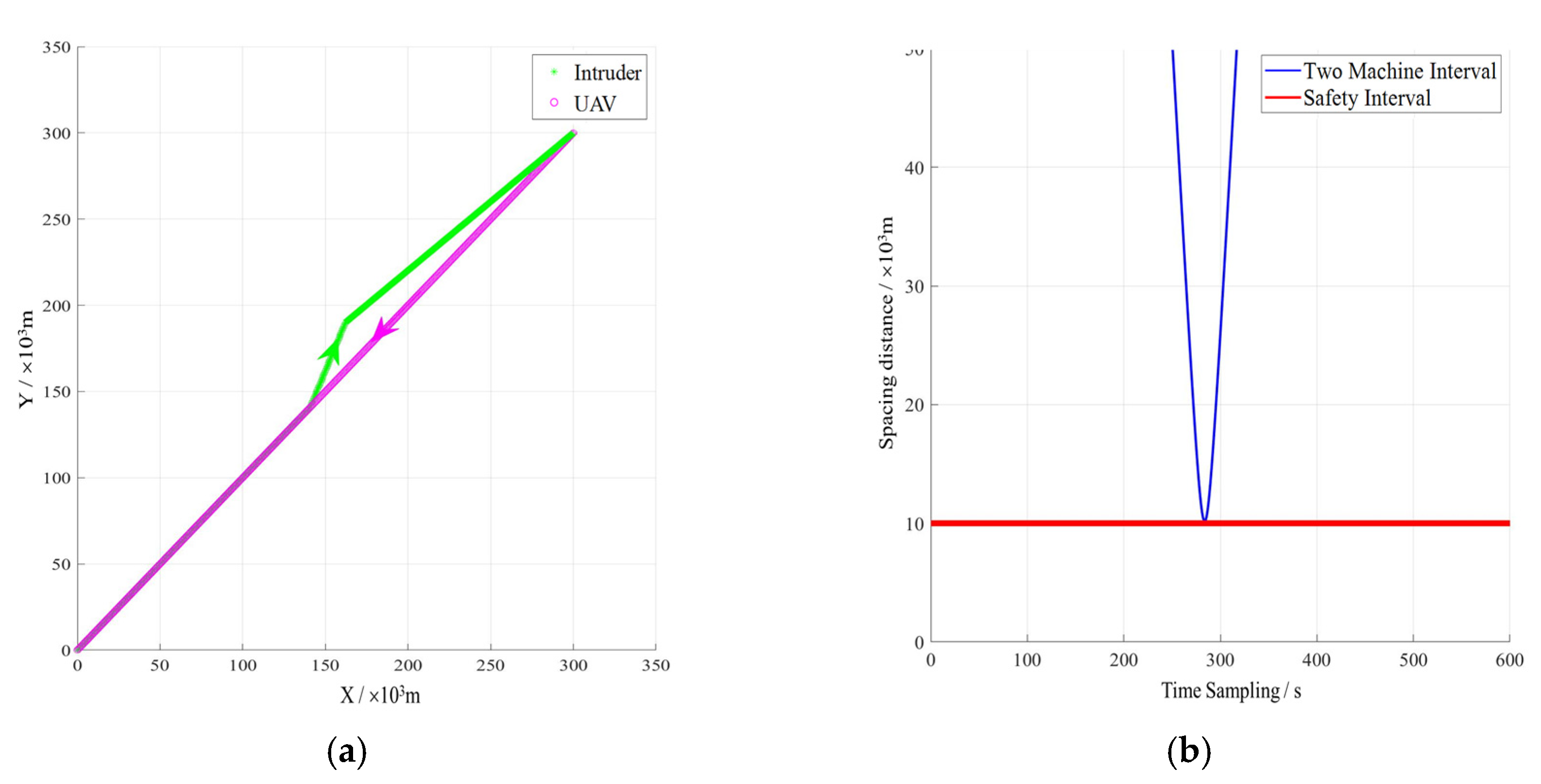
5.2. Conflict Resolution under Different Resolution Strategies
In order to verify the effectiveness of the improved velocity obstacle method in this paper, simulations are carried out to verify the different release methods separately. Considering the difference in performance between UAV and the actual operation, the speed size of UAV and intruder are set to and , respectively, the safety range radius of intruders is , the simulation step size is for both, the speed variation range of UAV is , and the heading variation range is rad. The initial position coordinates and heading of both are set separately according to different scenarios.
5.2.1. Speed Deliverance
The initial coordinates of the UAV is and the heading angle is , the initial position of the intruder is and the heading angle is . The simulation results are shown in Figure 9, the speed change of the UAV is , which satisfies the speed change range, and the interval between the two machines always satisfies the safety interval standard, so the selection of speed release is effective.
Figure 9.
Speed deliverance scenario analysis: (a) speed relief scenes; (b) two-machine interval.
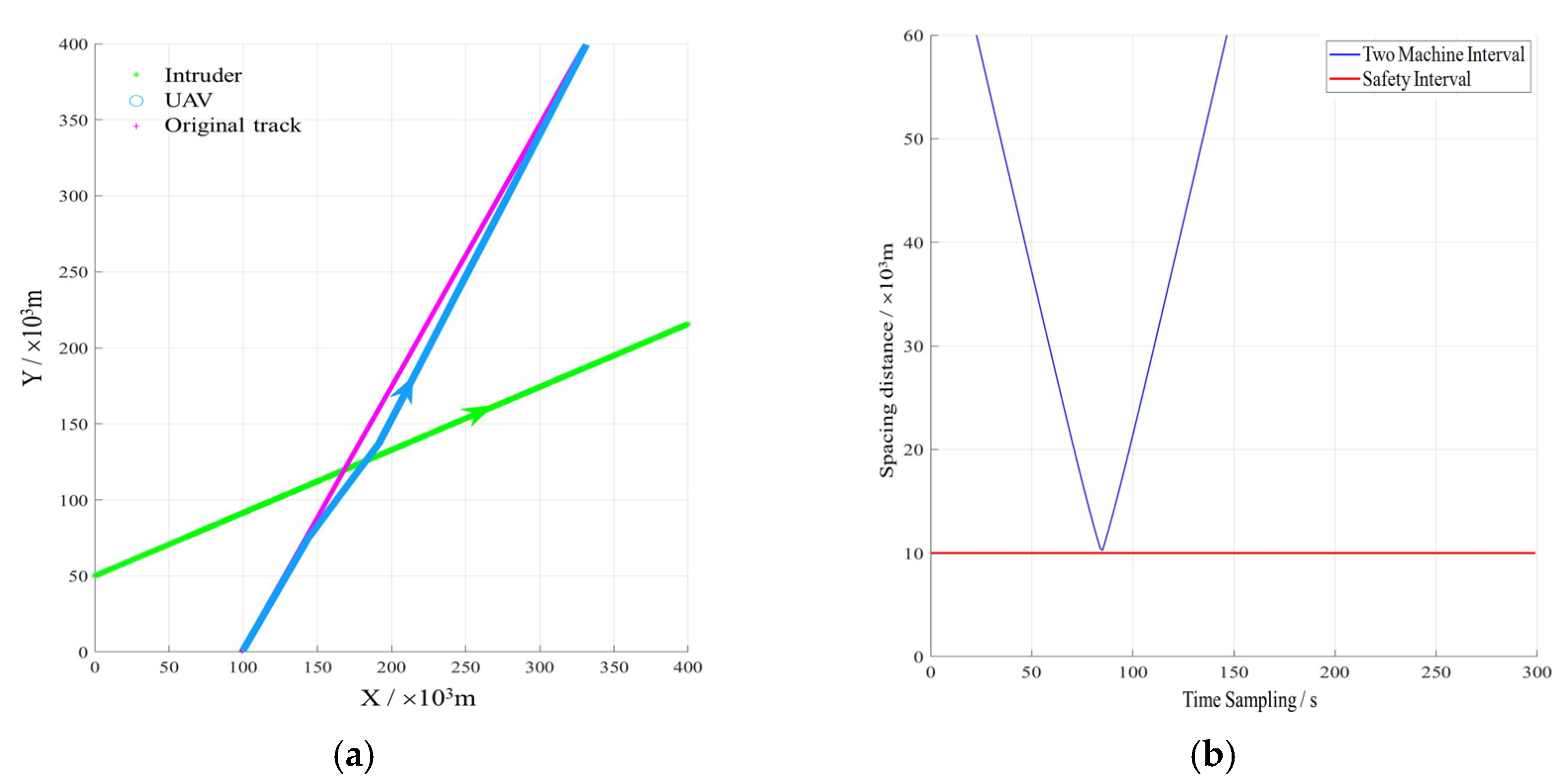
5.2.2. Sailing to Deliverance
The initial coordinate of the UAV is and the heading angle is , the initial coordinate of the intruder is and the heading angle is . The simulation results are shown in Figure 10, the UAV heading change is , which meets the angle range of heading change, and the interval between the two aircrafts always meets the safety interval standard.
Figure 10.
Voyage deliverance scenario analysis: (a) navigate to the relief scene; (b) two-machine interval.
5.2.3. Compound Deliverance
In the process of compound deconfliction, according to the relationship between the amount of speed change and the amount of heading change and the comprehensive utility function, the following relationship can be obtained. From Figure 11, it can be seen that when the speed change amount is 0, the minimum value of the composite utility function is 0 at this time, i.e., conflict resolution is performed by changing the heading only at this time.
Figure 11.
The relationship between the amount of speed change and the amount of heading change, and the integrated utility function: (a) the amount of speed change and heading change; (b) amount of velocity change and integrated utility function.
The initial coordinate of the UAV is and the heading angle is , the initial position of the intruder is , and the heading angle is . The simulation results are shown in Figure 12; the interval between the UAV and the intruder at is at the safety critical value. at this time, the UAV chooses to accelerate and turn to avoid the intruder at the same time. The change of speed is and the change of heading angle is , which meets the requirements of speed and heading change. According to the interval between the two aircrafts, it is known that the compound release can ensure that the interval between the two aircrafts is above the safe interval and achieve the purpose of conflict resolution.
Figure 12.
Compound relief scenario analysis: (a) compound deliverance scenario; (b) two-machine interval.
In summary, the results of the three simulations show that, according to the velocity obstacle method, choosing different decoupling strategies in different conflict scenarios can meet the condition that the interval between two aircraft is greater than or equal to the safety interval and ensure the flight safety of the UAV, which proves that the method is feasible and effective.
6. Conclusions
Based on the UAV flight conflict awareness scheme, this paper obtains the basic ADS-B data required during the UAV flight conflict resolution process. The ADS-B information is analyzed and applied to the UAV flight conflict resolution process, leading to the following conclusions:
(1) The use of ADS-B information can provide the basic data for UAV flight conflict perception, and potential flight conflicts can be detected after trajectory prediction;
(2) The applicability of UKF is better for nonlinear systems compared with EKF, and the computation is simple and the accuracy is better, the error is only about 50% of EKF;
(3) In different flight conflict scenarios, choosing different conflict resolution strategies according to the velocity obstacle method can meet the requirement that the interval between two aircrafts is greater than or equal to the safety interval, which can effectively improve the flight conflict resolution ability of UAV and ensure the flight safety of UAV and the smooth implementation of the mission.
When using UKF to predict the trajectory of unmanned aerial vehicles, the selection of initial values can have an impact on the prediction results. In engineering applications, an increase in calculation dimension also leads to an increase in the calculation workload. The collision avoidance process of a single UAV is mainly analyzed in this paper, and it is found that this collision avoidance method is effective. However, for UAV groups, the complexity of collision avoidance algorithms increases as the number of UAVs increases. Intersection phenomena may occur in collision avoidance schemes between UAVs. Future research will be focused on multi-UAVs instead of single one using the methods similar to that of [21,22,23,24,25,26,27,28,29,30,31].
Author Contributions
Conceptualization, X.G. and L.T.; methodology, M.L.; software, M.L. and L.T.; validation, L.T. and N.Y.; formal analysis, M.L.; investigation, L.T.; resources, Y.W.; data curation, N.Y.; writing—original draft preparation, L.T.; writing—review and editing, L.T.; visualization, X.G.; supervision, X.G.; project administration, N.Y.; funding acquisition, Y.W. All authors have read and agreed to the published version of the manuscript.
Funding
This work was funded by National Natural Science Foundation of China under Grant 52074309, Young Talent Support Project for Military Science and Technology under Grant 2022-JCJQ-QT-018, Young Talent Fund of Association for Science and Technology in Shaaxi under Grant 20220101, and Postdoctoral International Exchange Program Introduction Project under Grant YJ20220347.
Data Availability Statement
Not applicable.
Conflicts of Interest
The authors declare no conflict of interest.
Abbreviations
| UAV | Unmanned Aerial Vehicle |
| ADS-B | Automatic Dependent Surveillance-Broadcast |
| TCAS | Traffic Collision Avoidance System |
| UKF | Unscented Kalman Filter |
| ICAO | International Civil Aviation Organization |
| AES | Aircraft Earth Station |
| ACARS | Aircraft Communications Addressing and Reporting System |
| RGS | Remote Ground Station |
| KF | Kalman Filtering |
| EKF | Extended Kalman Filter |
| UT | Unscented Transformation |
| VO | Velocity Obstacle |
References
- Fu, Q.; Liang, X.; Zhang, J.; Li, Y.; Chen, Z.; Yan, F. A review of low-altitude traffic management system for unmanned aircraft. Flight Mech. 2019, 37, 1–6. [Google Scholar]
- Billmoria, K.D. A geometric optimization approach to aircraft conflict resolution. J. Sci. Food Agric. 2000, 82, 192–202. [Google Scholar]
- White, B.A.; Shin, H.S.; Tsourdos, A. UAV obstacle avoidance using differential geometry concepts. IFAC Proc. Vol. 2011, 44, 6325–6330. [Google Scholar] [CrossRef]
- Wu, M.; Wang, Z.; Wen, X.; Jiang, X.; Sun, Q. Geometric optimization model for flight conflict resolution. Syst. Eng. Electron. Technol. 2019, 41, 864–870. [Google Scholar]
- Du, Y.; Nan, Y. Research of robot path planning based on improved artificial potential field. In Proceedings of the 2016 2nd International Conference on Advances in Mechanical Engineering and Industrial Informatics (AMEII), Hangzhou, China, 9–10 April 2016; pp. 1025–1030. [Google Scholar]
- Zhao, J.; Bin, Y.; Run, Y. The flight navigation planning based on potential field ant colony algorithm. In Proceedings of the 2018 International Conference on Advanced Control, Automation and Artificial Intelligence (ACAAI 2018), Shenzhen, China, 21–22 January 2018. [Google Scholar]
- Zhang, N.; Zhang, Y.; Ma, C.; Wang, B. Path planning of six-DOF serial robots based on improved Artificial potential field method. In Proceedings of the 2017 IEEE International Conference on Robotics and Biomimetics (ROBIO) IEEE, Macau, China, 5–8 December 2017. [Google Scholar]
- Orozco-Rosas, U.; Montiel, O.; Sepulveda, R. Mobile robot path planning using membrane evolutionary artificial field. Appl. Soft Comput. 2019, 77, 236–251. [Google Scholar] [CrossRef]
- Guan, X.M.; Lu, R.L. Multi-vehicle conflict resolution method based on hybrid artificial potential field and ant colony algorithm. J. Wuhan Univ. Technol. 2020, 44, 28–33. [Google Scholar]
- Wu, J.; Zhang, J. Multi-machine free flight conflict resolution strategy using genetic algorithm. J. Intell. Syst. 2013, 8, 16–20. [Google Scholar]
- Zhao, H.; Tian, T. Dynamic state estimation of power systems based on adaptive Unscented Kalman Filtering. Powei Grid Technol. 2014, 38, 188–192. [Google Scholar]
- Wang, Z.; Xue, X.; Wang, Y. State parameter estimation of distributed drive electric vehicles based on adaptive Unscented Kalman Filtering. J. Beijing Univ. Technol. 2021, 38, 698–702. [Google Scholar]
- Wei, K.; Chen, Q. State estimation of lithium ion power batteries based on adaptive Unscented Kalman Filtering. Chin. J. Eltrical Eng. 2014, 34, 445–452. [Google Scholar]
- Shi, Y.; Han, C. Application of adaptive UKF algorithm in target tracking. J. Od Autom. 2011, 37, 755–759. [Google Scholar]
- Han, S.; Wang, W.; Chen, X.; Meng, W. High dynamic carrier tracking loop based on UKF quasi open loop structure. J. Aviat. 2010, 31, 2393–2399. [Google Scholar]
- Zhang, J. Modern Air Traffic Management; Beijing University of Aeronautics and Astronautics Press: Beijing, China, 2005. [Google Scholar]
- Wei, X.; Yao, D.; Dai, Z.; Han, Q. UAV flight conflict resolution technology based on path planning. Firepower Command. Control 2016, 41, 48–58. [Google Scholar]
- Lu, X.; Zhang, Y. Kalman filter algorithm-based ADS-B trajectory prediction. Mod. Inf. Technol. 2021, 5, 48–50+53. [Google Scholar]
- Chen, M.; Fu, J.Y. Research on flight track prediction method based on traceless Kalman filter. Comput. Simul. 2021, 38, 27–30+36. [Google Scholar]
- Zhang, W.; Zhu, M.; Chen, Z. Adaptive SLAM algorithm based on strong tracking UKF. Robotics 2010, 32, 190–195. [Google Scholar] [CrossRef]
- Zhang, H.; Gan, X.; Li, A.; Gao, Z.; Xu, X. UAV obstacle avoidance and trajectory recovery strategy based on velocity obstacle method. Syst. Eng. Electron. Technol. 2020, 42, 1759–1767. [Google Scholar]
- Ye, J.; Gao, J.; Zou, J.; Li, Q.; Cui, K. Verification and evaluation method of ILS safe operation state based on ADS-B data. In Proceedings of the 2020 IEEE 4th Information Technology, Networking, Electronic and Automation Control Conference (ITNEC), Chongqing, China, 12–14 June 2020; pp. 939–942. [Google Scholar]
- Raul-Cristian, R.; Radu-Emil, P.; Emil, M.P. Hybrid Data-Driven Fuzzy Active Disturbance Rejection Control for Tower Crane Systems. Eur. J. Control 2021, 58, 373–387. [Google Scholar]
- Chi, R.; Li, H.; Shen, D.; Hou, Z.; Huang, B. Enhanced P-Type Control: Indirect Adaptive Learning from Set-Point Updates. IEEE Trans. Autom. Control 2023, 68, 1600–1613. [Google Scholar] [CrossRef]
- Du, H.; Zhu, W.; Wen, G.; Duan, Z.; Lü, J. Distributed Formation Control of Multiple Quadrotor Aircraft Based on Nonsmooth Consensus Algorithms. IEEE Trans. Cybern. 2019, 49, 342–353. [Google Scholar] [CrossRef]
- Yu, J.; Dong, X.; Li, Q.; Lü, J.; Ren, Z. Adaptive Practical Optimal Time-Varying Formation Tracking Control for Disturbed High-Order Multi-Agent Systems. IEEE Trans. Circuits Syst. I Regul. Pap. 2022, 69, 2567–2578. [Google Scholar] [CrossRef]
- Ren, W. Consensus Tracking Under Directed Interaction Topologies: Algorithms and Experiments. IEEE Trans. Control Syst. Technol. 2010, 18, 230–237. [Google Scholar] [CrossRef]
- Cai, B.; Yang, J.; Shi, Y.; Zhang, L. Estimation for Fuzzy Semi-Markov Jump Systems With Indirectly Accessible Mode Information and Nonideal Data Transmission. IEEE Trans. Syst. Man Cybern. Syst. 2021, 51, 4016–4027. [Google Scholar] [CrossRef]
- Yang, J.; Ning, Z.; Zhu, Y.; Zhang, L.; Lam, H.K. Semi-Markov jump linear systems with bi-boundary sojourn time: Anti-modal-asynchrony control. Automatica 2022, 140, 110270. [Google Scholar] [CrossRef]
- Lv, M.; de Schutter, B.; Baldi, S. Non-Recursive Control for Formation-Containment of HFV Swarms with Dynamic Event-Triggered Communication. IEEE Trans. Ind. Inform. 2023, 19, 3188–3197. [Google Scholar] [CrossRef]
- Lv, M.; Chen, Z.; de Schutter, B.; Baldi, S. Prescribed-performance tracking for high-power nonlinear dynamics with time-varying unknown control coefficients. Automatica 2022, 146, 110584. [Google Scholar] [CrossRef]
Disclaimer/Publisher’s Note: The statements, opinions and data contained in all publications are solely those of the individual author(s) and contributor(s) and not of MDPI and/or the editor(s). MDPI and/or the editor(s) disclaim responsibility for any injury to people or property resulting from any ideas, methods, instructions or products referred to in the content. |
© 2023 by the authors. Licensee MDPI, Basel, Switzerland. This article is an open access article distributed under the terms and conditions of the Creative Commons Attribution (CC BY) license (https://creativecommons.org/licenses/by/4.0/).