Abstract
To produce multi-modal mobility in complicated situations is a significant issue for soft robots. In this study, we show the conception, construction, and operation of an inchworm-impersonating dielectric elastomer-activated soft robot. The robot is small and lightweight, weighing only 3.5 g, and measuring an overall 110 mm by 50 mm by 60 mm (length, width, and height). The three mobility modes for the robot are each equipped with a detailed mechanism. When the excitation voltage is 5 kV, the robot runs forward under a frequency of stimulation of 1–9 Hz, and its direction of motion changes to a backwards motion at >10 Hz. When the excitation voltage of 5.5 kV is applied to the robot, the robot runs forward at 1–12 Hz frequency and moves in the opposite direction at 13 Hz, reaching the fastest reverse speed of 240 mm/s. When the excitation voltage rises to 6 kV, the robot reaches its fastest running speed of 270 mm/s at 14 Hz. Motivated by high voltage and high duty cycle, the robot can jump over obstacles of 5 mm. In order to assess the performance of backward running, the speed achieved by the robot under a 30% duty cycle and a 50% duty cycle was compared, as well as the speed of the robot with or without the use of a counterweight. The robot has a simpler design and construction than earlier soft robots of the same kind, as well as a quicker speed, a wider variety of movement modes, and other notable advantages.
1. Introduction
In a complicated environment, inchworms, which are arthropods, may travel ahead and jump over barriers. Their soft bodies and strong muscles contribute to their agility and resilience [1]. They have served as an inspiration for the creation of bionic soft robots that can carry out difficult detecting tasks in a chaotic and unpredictable environment [2].
Traditional robots tend to have stiff constructions, which are less safe and flexible [3,4,5]. On the other hand, the soft robot is a novel kind of robot composed of flexible or telescopic materials that has limitless degrees of freedom, remarkable agility, and inherent elasticity [6,7,8]. The driving materials used by existing software robots mainly include: shape memory material [9], responsive hydrogel [10], ionic polymer metal composite [11], pneumatic [12], and hydraulic [13]. Compared with other driving materials, the dielectric elastomer (DE) has the benefits of light weight, low cost, fast response (0.1 ms), high efficiency (60–90%), high energy density (>3.4 MJ·m−3), and large strain range (0–380%) [14,15,16], having substantial advantages in bionic robots. Dielectric elastomer is a kind of hyperelastic thin film material, which attracts much attention due to its wide application in soft robots [17], bionic muscles [18], etc. Acrylic elastomers (VHB 4910 and VHB 4905, 3M) are the most used materials in the experiment because they are available on the market at a low price [19]. However, due to the complex interaction between nonlinear material behavior and driving electrostatic force, DEA is prone to electromechanical instability when driving [20,21,22,23].
Some achievements have been made in the research of dielectric elastomer soft robot. Conn et al. [24] discovered a bionic inchworm robot that utilizes aerodynamically coupled DE film to generate inchworm-like movement. The robot is composed of repeated body fragments, the total length can be adjusted by adding or deleting fragments. However, the robot’s top speed is only 4.1 mm/s. Cao et al. [25] reported an untethered soft robot using soft electrostatic actuators. It is one of the first efforts to develop an untethered soft robot based on DEAs. However, the main electrical components of the robot are made of hard materials. The robot is far from completely soft and has poor body flexibility. Zhao et al. [26] designed a soft robot composed of two actuators. The robot can run fast on land, reaching a speed of 51.83 cm/s. However, it is limited to plane single-direction motion. Li et al. [27] designed a dielectric elastomer-driven soft robot with omni-directional movement ability. It is composed of six segments of DE, has a six-segment annular structure with three movement mechanisms of rolling, creeping, and peristalsis. Nevertheless, the stability of rolling walking mode is limited. When it comes to jumping, Luo et al. [28] developed a jumping robot made of 20 layers DE, which can give 30 N force and jump up to 45 mm. However, it is complicated in design and production and cannot move forward to overcome obstacles. Yeh et al. [29] constructed robots that could jump and crawl in horizontal and vertical pipes. The robot’s working environment, on the other hand, is limited to the pipe. Duduta et al. [30] reported the first ever jumping mechanism driven by a power-amplified dielectric elastomer actuator. They investigated soft systems, capable of jumping repeatedly in unstructured environments with no need for precise landings. However, this structure cannot determine the direction of jumping. In the current research, the land soft robot has defects, for example, single movement mode, slow movement speed or complex fabrication.
This research provides a revolutionary robot with a basic construction that imitates the movement of the inchworm, in contrast to the DEA-actuated robots mentioned before. To provide electrostatic actuation with high power density, we use a stretchy dielectric. To produce diverse locomotion, we use two sets of curved bottoms with varying friction. Inspired by inchworm, robot moves through alternating expansion/contraction of body and adhesion/separation of feet. It can achieve multi-mode movement in addition to having the qualities of great elasticity, quick speed, and convenient construction. The concept and construction of the bionic inchworm robot have been presented in Section 2. Later, in Section 3, the fundamentals of the robot’s three motion modes are given in depth. Section 4 presents the findings of the experiments performed to evaluate the robot’s mobility capabilities, and Section 5 provides a discussion.
2. Materials and Methods
2.1. Design
The inchworm moves at a peristaltic crawling pace (Figure 1a). Having a deformable body with foot pads situated at two ends, the inchworm moves in a cycle by first firmly anchoring its rear foot to the surface and extending its body forward, and then firmly anchoring its front foot to the surface and bringing the rear section of its body to meet the forward part. The inchworm’s soft muscles act as a strong propulsion for movement. The inchworm’s forefoot and hind foot make distinct connections to the Earth at various stages. The tentacle’s foot pads (Figure 1c) play a significant role in its locomotion by acting as a source of powerful friction support. Inspired by the features of inchworm’s movement mode, the bionic inchworm soft robot is designed. The structure of the bionic inchworm robot is described in Figure 1b. A predetermined DE membrane acts as the soft muscle, an elastomeric frame acts as the soft body, and two pairs of curved bottoms act as the robot’s feet. To replicate the inchworm’s foot pads, silica gel is given to a specific area of the rear foot (Figure 1d).
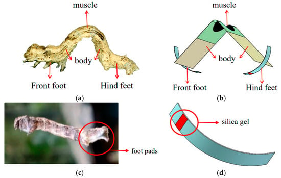
Figure 1.
Structure model of bionic inchworm robot. (a) Structure of the inchworm; (b) Bionic inchworm robot structure; (c) The foot pads of the hind foot of an inchworm; (d) Silica gel at the bionic inchworm robot hind foot.
2.2. Fabrication
The detailed fabrication of the bionic inchworm robot is shown in Figure 2. We built the robot by integrating components of actuator and feet. First, two layers of dielectric elastomer material (VHB4910, 3M, Shanghai, China) are pre-stretched to 400% × 400%. As the flexible electrodes, carbon grease (NYOGEL-756G, Nye, USA) is smeared on either side of the films (Figure 2a). Next, the finished two membranes are stacked together between the main frame (Polyethylene terephthalate (PET), 0.188 mm thick, China) and the stiffener (PET, 0.25 mm thick). The fulfilled actuator, which is also known as the DEA, automatically bends under the elastic force of the pre-tensioned film, as shown in Figure 2b. Then, the PET plate (0.188 mm thick) is partially heated to type a curved bottom (Figure 2c). Silica gel is applied at the position where the hind foot contacted the ground to simulate the foot pads of the tentacles of the inchworm. Eventually, utilizing PET (0.25 mm thick) as the linked plate, the arc bottoms are connected to both ends of the actuator by cyanoacrylate glue. The finished bionic inchworm soft robot is depicted in Figure 2d, with a total weight of 3.5 g.
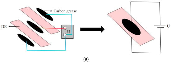
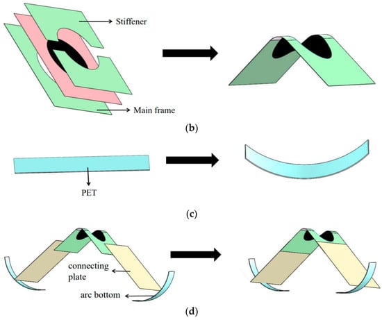
Figure 2.
Manufacturing process of the bionic inchworm soft robot. (a) Pre-stretching of DE and coating of electrodes. The carbon grease on both sides is connected to the negative electrode (“-”), and the carbon grease in the middle is connected to the positive electrode (“+”); (b) Fabrication of actuator; (c) Fabrication of arc bottom; (d) Assembly of bionic inchworm soft robot.
3. Multimodal Motion and Its Principle
3.1. Robotic Body
The signal generator (DG4062, RIGOL, Beijing, China) and the voltage amplifier (Trek 10/10B-HS, Trek, USA) are connected to create the high voltage that powers the soft robot. Through the use of a signal generator and a voltage source, low voltage is produced. A voltage amplifier is then used to increase the voltage to the kilovolt level. Through the three feed lines, we apply voltage to the robot body to actuate it (Figure 2a). One of the wires connects the inner carbon grease to the positive electrode and the wire is clamped and secured by DE film on both sides. The other two wires, respectively, connect the external carbon grease to the negative pole and are clamped and fixed by the frame and stiffener. As shown in Figure 3a, the robot produces a particular force to propel it into motion after receiving electrical stimulation.
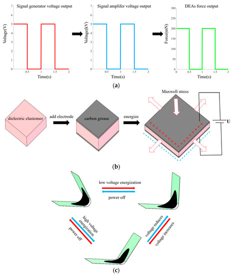
Figure 3.
Periodic movement of actuator. (a) The transmission process of signal through voltage source, signal generator and voltage amplifier; (b) Actuation principle of dielectric elastomer; (c) Status of DEA under power on and power off.
After pre-stretching, the DE film has a certain strain energy stored in it. As soon as the actuator is released, it will bend due to the membrane’s strain energy, creating a unique saddle surface shape with a certain bending angle. Currently, a portion of the membrane’s strain energy will be transferred into the flexible frame’s bending deformation energy. The film will compress in the thickness direction after supplying a voltage of kilovolts to the actuator’s electrode regions, while expanding in the length and breadth direction under Maxwell stress (Figure 3b). The film strain energy will not be adequate to sustain the present bending angle as a result of the internal stress brought on by the membrane’s pre-tension being countered by this. The actuator will turn at an angle in the direction of the plane state. The Maxwell stress vanishes and the actuator rotates back to its initial bending condition when the actuator is turned off. When a periodic square wave voltage is delivered to the actuator, as illustrated in Figure 3b, the actuator experiences periodic variations in angle.
Maxwell stress can be expressed as [31]:
is the Maxwell stress; F/m is the vacuum permittivity; and is the dielectric constant of dielectric elastomer film. U indicates the voltage applied across the membrane and t presents the thickness of the DE film.
3.2. Robotic Feet
The feet work as depicted in Figure 4.
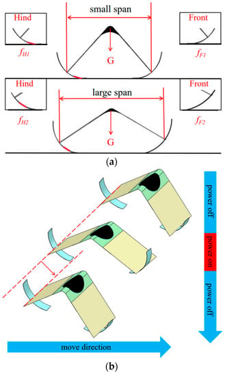
Figure 4.
The working mechanism of the feet. (a) The working mechanism of friction; (b) The movement of the feet.
The friction can be stated as follows when the mass is constant:
where f is the friction, is the friction coefficient, and G is gravity. The friction of the front and rear feet of the robot is treated asymmetrically. Silica gel is applied to the initial position of the back foot in contact with the ground, whereas the front foot is not treated. Each foot’s friction can be expressed as follows:
is the friction generated by the forefoot, is the friction coefficient of the forefoot, is the friction generated by the rear foot, and is the friction coefficient of the rear foot.
The actuator may be bent by the robot to change the state of contact between its feet and the ground, as seen in the Figure 4a. The distance between the two end points of the PET frame is used to determine the span of the robotic body. The electricity is off and the body is in a small span while at rest. The silicone-coated portion of the rear foot makes contact with the ground at this moment, increasing the friction coefficient of the rear foot relative to the front foot. So, when the robot is in the state of contraction. The span grows when the actuator is powered up. As a result, the position of the rear foot coated with silica departs the ground. Both front and rear feet are in direct contact with the ground. Under these conditions, the friction coefficient of the back foot and the front foot are basically equivalent because both feet are of the same material. So, when the robot is in an extended state. In this case, motion inertia plays a significant role in determining the robot’s subsequent movement.
3.3. Principle of Forward Running
On acrylic plates, the inchworm soft robot can run quickly. When the actuator is not powered, it is in its initial condition. In this instance, silicone is used to cover the area where the back foot makes contact with the acrylic plate, and the friction on the back foot is greater than on the front foot. By energizing the actuator, the robotic body expands. Both the front and back feet have a propensity to spread out. Due to the silicone’s ability to inhibit movement (Figure 5a), the back foot is anchored, causing the front foot to advance (Figure 5b). Both the robot’s front and back feet have a propensity to retreat inward when the soft robot is contracting. Due to the inertia of moving forward, the front foot stays on the ground, which causes the rear foot to contract (Figure 5c). Figure 5 shows how the robot advances as a whole. The actuator is periodically deformed by the applied periodic square wave voltage, which drives the front and back feet’s alternating fixation and movement and moves the soft robot as a whole.
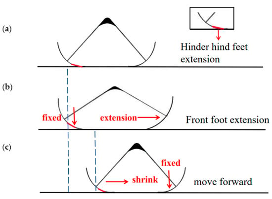
Figure 5.
Forward running principle. Positioning the rear foot of the robot with a blue dotted line indicates that the robot is moving forward. (a) Power off state, hind foot fixed; (b) Power on situation, front foot extension; (c) Power off state, front foot fixed, hind foot shrink, robot moves forward.
3.4. Principle of Backward Running
While the front foot remains unaffected, the back foot’s point of contact with the acrylic plate is covered with silica gel. This asymmetric design enables the silica gel in the back foot to perform a variety of functions at varying frequencies, allowing the robot to execute varied movements. The silica gel of the rear foot plays a role in blocking the expansion of the rear foot when the frequency of stimulation is low, allowing the robot movement to advance. The applied high frequency square wave voltage allows the actuator to quickly repeat periodic expansion–contraction when the energizing frequency is increased to a specific amount. Electric stimulation stretches the actuator once more before it completely shrinks to the starting angle. As a result, the robot’s body span is greater at high frequency than it is at low frequency. The silicone that has been applied to the rear foot cannot make contact with the acrylic plate in this condition. It now serves the purpose of blocking the contraction of the rear foot, rather than impeding the expansion of the back foot. When the soft robot contracts, both the front and back feet typically move inward, as seen in Figure 6. The forefoot contracts while the rear foot remains locked in place because the silicone in the hind foot prevents its contraction (Figure 6a). When the robot is powered up, its rear foot extends backward and its front foot is essentially locked due to the inertia of moving backward (Figure 6c). This periodic motion causes the robot to travel in the opposite direction.
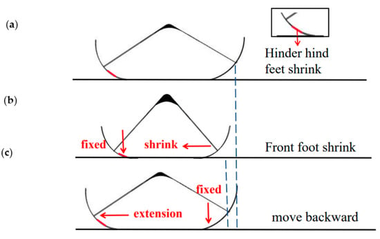
Figure 6.
Backward running principle. Positioning the front foot of the robot with a blue dotted line indicates that the robot is moving backward. (a) Power on state, hind foot fixed; (b) Power off state, front foot shrinks; (c) Power on state, front foot fixed, hind foot extension, robot moves backward.
3.5. Principle of Jumping
The key to jumping robots is how to achieve the jumping motion. This can be achieved by providing the robot with high enough excitation, i.e., high voltage (6 kV), high frequency and high duty cycle (80%). As a result, the robot can fully store energy, thus achieving the jumping function. The robot can effectively overcome the 5 mm impediment by moving forward.
4. Experiments and Results
4.1. Backward Running
The robot may go backwards when subjected to high-frequency electricity, as shown in Figure 7a. Experimental footage was taken using a cell phone camera, and then the robot’s running distance within a second was calculated to determine its average speed. All investigations used the same robot built with the same actuator to guarantee data consistency. By comparing the running speed of 30% duty cycle and 50% duty cycle, it can be seen that 30% duty cycle is more conducive to the running of the robot (see Section 5). Thus, we used 30% duty cycle uniformly in the running experiment. The experimental results are shown in Figure 7b. At 5 kV and within 1–15 Hz, the robot’s forward movement speed increases as the frequency increases, peaks at 8 Hz, and subsequently decreases. The robot reverses direction at 10 Hz of frequency. After achieving its greatest speed of 240 mm/s at 14 Hz, the rearward movement speed steadily declines. Under the condition of 5.5 kV, the robot’s forward running speed progressively rises, then falls after achieving its maximum speed at 11 Hz. The robot then proceeds at 13 Hz in the opposite direction, achieving a top speed of 240 mm/s. As frequency rises, the reverse motion velocity steadily decreases.
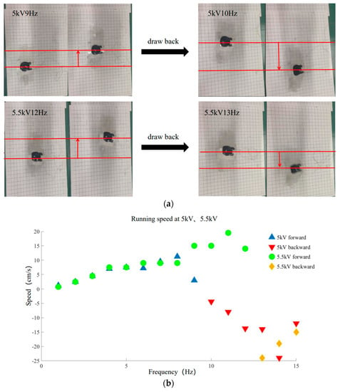
Figure 7.
Backward running experiment. (a) Backward running experimental 5 kV and 5.5 kV. Red line positioning robot is used to indicate the running direction of robot; (b) Running speed of 1–15 Hz at 5 kV, 5.5 kV.
4.2. Forward Running
High voltage (6 kV) is used to achieve the quickest operating speed feasible. However, in this case, the friction is insufficient because of the low weight of the arc bottom. The arc bottoms slide on the acrylic plate. Therefore, it is crucial to gain the arc bottoms’ weight under the condition of 6 kV in order to increase its friction. To gain the weight of the arc bottom, a pair of 2 mm-thick arc bottoms are 3D printed (polylactic acid (PLA)), as shown in Figure 8a. The robot after counterweight weighs 8 g. The experimental results are shown in Figure 8b. In this case, the robot with sufficient friction will no longer move backward at high frequency and will move forward all the way. Figure 8b demonstrates that the robot’s speed increases gradually between 1 Hz and 15 Hz after counterweighting. The robot can move at a maximum speed of 270 mm/s at 14 Hz.
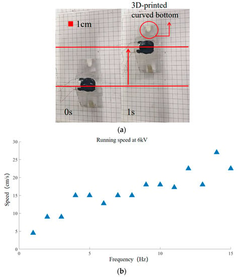
Figure 8.
Forward running experiment. (a) Running experiment after counterweight. Red line positioning robot is used to indicate the forward direction of robot; (b) Running speed of 1–15 Hz at 6 kV.
The following Table 1 compares the land running performance of the robot styled in this paper with that of other soft robots. It can be observed that although the ring dielectric elastomer-driven robot [27] has full range of motion capability, its speed is slow. The insect-scale robot [32] can only achieve unidirectional movement despite its higher speed. The bionic inchworm soft robot designed in this research not only has a fast run speed, but also has bi-directional motion capability. Existing research in the realm of soft robotics has not mentioned this.

Table 1.
Comparison of land running speed with other soft robots.
4.3. Jumping
The soft robot can swiftly jump over restrictions without complex fabrication and control, which is difficult to implement with fully soft materials at small scale. Firstly, the front foot of the robot touches the obstacle (Figure 9a). The robot then jumps, crossing the obstacle with its front foot (Figure 9b). The robot keeps moving forward until its back foot collides with the obstruction (Figure 9c). Finally, the rear foot of the robot crosses the obstacle (Figure 9d). As depicted in Figure 9, the bionic inchworm soft robot completes the whole obstacle-crossing process at 6 kV 10 Hz and 80% duty cycle. Few existing DE-based soft robots can achieve both running and jumping on the ground. The implementation of obstacle surmounting proves that the robot has better terrain adaptability and autonomous movement ability.

Figure 9.
Jumping experiment. (a) Front foot touches obstacle; (b) Front foot jumps over obstacle; (c) Rear foot touches obstacle; (d) Rear foot jumps over obstacle.
Table 2 compares the skipping performance of the robot designed in this research with that of other soft robots. The pipe robot [29] is made of 6 elastic ribbons with a jump height of 60 mm, however its working environment is limited to the pipe. The jumping robot [28] has a maximum jumping height of 45 mm. However, its fabrication is difficult, and the robot’s jumping needs 60 s of energy storage time. The inchworm robot styled in this research is simpler to design and manufacture. Only two layers of DE are required to obtain a leap height of 5 mm, and the energy storage time is quite short. With forward movement, it can realize the function of obstacle crossing.

Table 2.
Comparison of jumping function with other soft robots.
5. Discussion
In order to improve running performance and debate the reverse motion situation, the experiment examined the speed at duty ratios of 30% and 50%, and with or without arc bottom weighting under 5 kV and 5.5 kV, respectively. Figure 10 shows the findings of the comparison tests. The robot’s backward running speed is seen to be greater with the same excitation voltage while operating at a 30% duty cycle. The robot will be stimulated for longer durations of time inside a single cycle if the duty cycle rises over 30%. Since the robot has more energy stored, it is simpler to overcome the resistance that the silicone on the back foot presents. This implies that the silicone used to treat the back foot cannot effectively stop the back foot from contracting. Therefore, increasing the duty cycle slows the robot’s backward motion. Too little incentive time will further weaken the incentive force if the duty cycle is decreased to less than 30%, making it difficult to create a decent running effect. Therefore, a duty ratio of 30% is a suitable requirement for the robot to travel backward. On the other hand, the robot will not move back when the weight of the arc bottom is raised. This is the result of enough friction in this situation. The friction on the back foot is too much for the force the actuator can provide to move it. The silica gel always prevents the back foot from extending, which forces the robot to go forward. In conclusion, the lightest feasible arced bottom as possible is a necessary condition for the robot to move backwards at high frequencies. A relatively low duty cycle is more conducive to the robot to travel rearward.
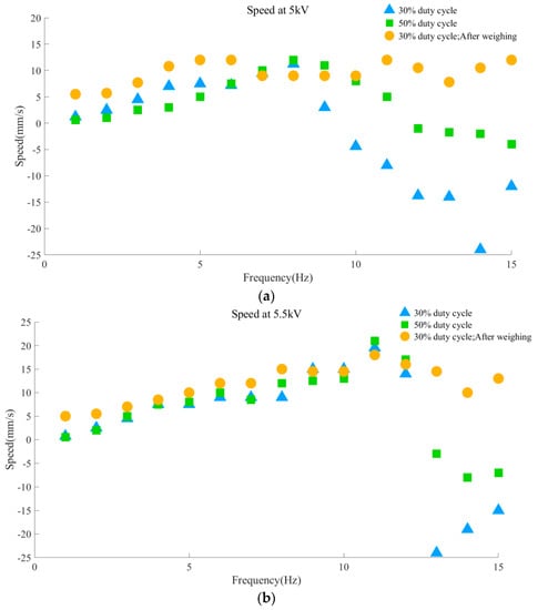
Figure 10.
Contrast experiments. (a) Speed comparison of different duty cycle and weight of arc bottom at 5 kV; (b) Speed comparison of various duty cycles and weights of arc bottom at 5.5 kV.
When the robot only moves forward after gaining weight, the running speed of the robot at three voltages is also compared. It can be seen that the forward running speed of the robot shows the law of 5 kV < 5.5 kV < 6 kV (Figure 11). In other words, the speed of the robot is proportional to the excitation voltage. The voltage induced compression force Factive can be considered as the product of an equivalent Maxwell stress and an equivalent cross-sectional area of the actuator associated with the deformation [33]. Since the Maxwell stress is proportional to the square of the electric field, Factive can be written as:
where U is the applied voltage and g(x) is a function of the change in displacement x related to the deformation. Therefore, higher excitation voltage makes the actuator produce greater driving force to drive the robot to run faster.
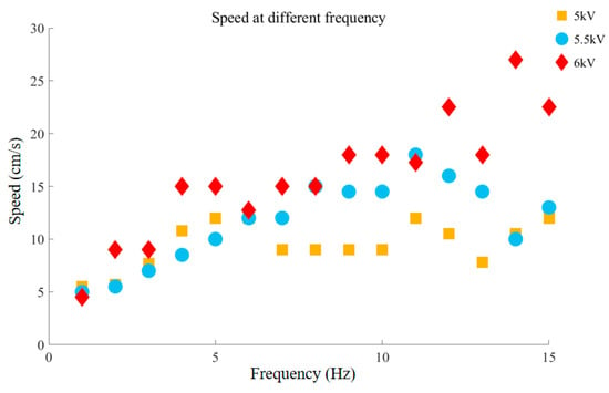
Figure 11.
Comparison of forward running speed under different voltages.
6. Conclusions
In conclusion, we developed a DEA-actuated soft robot with high durability, multimodal mobility, and rapid motion. The inchworm serves as the model for the running mechanism. The curved bottom with varied friction is meant to achieve motion in a forwards and backwards direction at various frequencies. It is lightweight and tiny. The robot can regain rapid running, bidirectional motion, and leaping by altering voltage, duty cycle, and frequency.
Future work of this project includes the development of a dynamic model that fully reflects the multi-modal motion of the robot. In addition, the robot still needs wires to connect external circuits. How to develop an untethered soft robot based on DEA is intriguing and deserves further investigations. Finally, we will work on the development of a sensory feedback control based on the self-sensing capability of the DEA.
Author Contributions
Writing—original draft preparation, Z.J.; writing—review and editing, Q.L.; data analysis, W.S.; funding, Y.C. All authors have read and agreed to the published version of the manuscript.
Funding
Grateful acknowledgement is given to the National Natural Science Foundation of China with Grant No. 52075293, Natural Science Foundation of Shandong Province with Grant No. ZR2019MEE019 and Research Project of Teaching Reform for Shandong University at Weihai with Grant No. Z2019022.
Data Availability Statement
Not applicable.
Conflicts of Interest
The authors declare no conflict of interest.
References
- Van Griethuijsen, L.I.; Trimmer, B.A. Locomotion in caterpillars. Biol. Rev. 2014, 89, 656–670. [Google Scholar]
- Cao, J.; Liang, W.; Wang, Y.; Lee, H.P.; Zhu, J.; Ren, Q. Control of a soft inchworm robot with environment adaptation. IEEE Trans. Ind. Electron. 2019, 67, 3809–3818. [Google Scholar]
- Nehme, H.; Aubry, C.; Solatges, T.; Savatier, X.; Rossi, R.; Boutteau, R. LiDAR-based Structure Tracking for Agricultural Robots: Application to Autonomous Navigation in Vineyards. J. Intell. Robot. Syst. 2021, 103, 61. [Google Scholar]
- Nashat, N.; Elsheikh, G.A.; Ouda, A.N.; Emara, T. Design and Implementation of a Wireless Medical Robot for Communication Within Hazardous Environments. Wirel. Pers. Commun. 2021, 122, 21–22. [Google Scholar]
- Duduta, M.; Berlinger, F.; Nagpal, R.; Clarke, D.R.; Wood, R.J.; Temel, F.Z. Tunable Multi-Modal Locomotion in Soft Dielectric Elastomer Robots. IEEE Robot. Autom. Lett. 2020, 5, 3868–3875. [Google Scholar]
- Bao, G.; Fang, H.; Chen, L.; Wan, Y.; Xu, F.; Yang, Q.; Zhang, L. Soft Robotics: Academic Insights and Perspectives Through Bibliometric Analysis. Soft Robot. 2018, 5, 229–241. [Google Scholar]
- Alici, G. Softer is Harder: What Differentiates Soft Robotics from Hard Robotics? MRS Adv. 2018, 3, 1557–1568. [Google Scholar]
- Wu, K.; Zheng, G. Simulation and control co-design methodology for soft robotics. In Proceedings of the 2020 39th Chinese Control Conference (CCC), Shenyang, China, 27–29 July 2020; pp. 3910–3914. [Google Scholar]
- Lee, H.T.; Kim, M.S.; Lee, G.Y.; Kim, C.-S.; Ahn, S.-H. Shape Memory Alloy (SMA)-Based Microscale Actuators with 60% Deformation Rate and 1.6 kHz Actuation Speed. Small 2018, 14, 1801023. [Google Scholar]
- Lee, Y.; Song, W.J.; Sun, J.Y. Hydrogel soft robotics. Mater. Today Phys. 2020, 15, 100258. [Google Scholar]
- Rukhlenko, I.D.; Farajikhah, S.; Lilley, C.; Georgis, A.; Large, M.; Fleming, S. Performance Optimization of Polymer Fibre Actuators for Soft Robotics. Polymers 2020, 12, 454. [Google Scholar]
- Walker, J.; Zidek, T.; Harbel, C.; Yoon, S.; Strickland, F.S.; Kumar, S.; Shin, M. Soft Robotics: A Review of Recent Developments of Pneumatic Soft Actuators. Actuators 2020, 9, 3. [Google Scholar]
- Fan, J.; Wang, S.; Yu, Q.; Zhu, Y. Swimming performance of the frog-inspired soft robot. Soft Robot. 2020, 7, 615–626. [Google Scholar]
- Meng, J.; Qiu, Y.; Hou, C.; Zhang, Q.; Li, Y.; Wang, H. Bistable dielectric elastomer actuator with directional motion. Sens. Actuators A: Phys. 2021, 330, 112889. [Google Scholar]
- Neu, J.; Hubertus, J.; Croce, S.; Schultes, G.; Seelecke, S.; Rizzello, G. Fully Polymeric Domes as High-Stroke Biasing System for Soft Dielectric Elastomer Actuators. Front. Robot. AI 2021, 8, 695918. [Google Scholar]
- Bruschi, A.; Donati, D.M.; Choong, P.; Lucarelli, E.; Wallace, G. Dielectric elastomer actuators, neuromuscular interfaces, and foreign body response in artificial neuromuscular prostheses: A review of the literature for an in vivo application. Adv. Healthc. Mater. 2021, 10, 2100041. [Google Scholar]
- Youn, J.-H.; Jeong, S.M.; Hwang, G.; Kim, H.; Hyeon, K.; Park, J.; Kyung, K.-U. Dielectric elastomer actuator for soft robotics applications and challenges. Appl. Sci. 2020, 10, 640. [Google Scholar]
- Franke, M.; Ehrenhofer, A.; Lahiri, S.; Henke, E.-F.M.; Wallmersperger, T.; Richter, A. Dielectric Elastomer Actuator Driven Soft Robotic Structures with Bioinspired Skeletal and Muscular Reinforcement. Front. Robot. AI 2020, 7, 510757. [Google Scholar]
- Guo, Y.; Liu, L.; Liu, Y.; Leng, J. Review of dielectric elastomer actuators and their applications in soft robots. Adv. Intell. Syst. 2021, 3, 2000282. [Google Scholar]
- Sharma, A.K.; Arora, N.; Joglekar, M.M. DC dynamic pull-in instability of a dielectric elastomer balloon: An energy-based approach. Proc. R. Soc. A Math. Phys. Eng. Sci. 2018, 474, 20170900. [Google Scholar]
- Sharma, A.K.; Bajpayee, S.; Joglekar, D.M.; Joglekar, M.M. Dynamic instability of dielectric elastomer actuators subjected to unequal biaxial prestress. Smart Mater. Struct. 2017, 26, 115019. [Google Scholar]
- Khurana, A.; Kumar, A.; Raut, S.K.; Sharma, A.K.; Joglekar, M. Effect of viscoelasticity on the nonlinear dynamic behavior of dielectric elastomer minimum energy structures. Int. J. Solids Struct. 2021, 208, 141–153. [Google Scholar]
- Sharma, A.K. Design of a command-shaping scheme for mitigating residual vibrations in dielectric elastomer actuators. J. Appl. Mech. 2020, 87, 021007. [Google Scholar]
- Conn, A.T.; Hinitt, A.D.; Wang, P. Soft segmented inchworm robot with dielectric elastomer muscles. Electroact. Polym. Actuators Devices (EAPAD) 2014, 9056, 638–647. [Google Scholar]
- Cao, J.; Qin, L.; Liu, J.; Ren, Q.; Foo, C.C.; Wang, H.; Lee, H.P.; Zhu, J. Untethered soft robot capable of stable locomotion using soft electrostatic actuators. Extrem. Mech. Lett. 2018, 21, 9–16. [Google Scholar]
- Zhao, J.; Zhang, J.; McCoul, D.; Hao, Z.; Wang, S.; Wang, X.; Huang, B.; Sun, L. Soft and fast hopping–running robot with speed of six times its body length per second. Soft Robot. 2019, 6, 713–721. [Google Scholar]
- Li, W.B.; Zhang, W.M.; Zou, H.X.; Peng, Z.-K.; Meng, G. Multisegment annular dielectric elastomer actuators for soft robots. Smart Mater. Struct. 2018, 27, 115024. [Google Scholar]
- Luo, B.; Li, B.; Yu, Y.; Meng, Y. A Jumping Robot Driven by a Dielectric Elastomer Actuator. Appl. Sci. 2020, 10, 2241. [Google Scholar]
- Yeh, C.Y.; Chen, C.Y.; Juang, J.Y. Soft hopping and crawling robot for in-pipe traveling. Extrem. Mech. Lett. 2020, 39, 100854. [Google Scholar]
- Duduta, M.; Berlinger FC, J.; Nagpal, R.; Clarke, D.R.; Wood, R.J.; Temel, F.Z. Electrically-latched compliant jumping mechanism based on a dielectric elastomer actuator. Smart Mater. Struct. 2019, 28, 09LT01. [Google Scholar]
- Pelrine, R.; Kornbluh, R.; Pei, Q. High-speed electrically actuated elastomers with strain greater than 100%. Science 2000, 287, 836–839. [Google Scholar]
- Li, T.; Zou, Z.; Mao, G.; Yang, X.; Liang, Y.; Li, C.; Qu, S.; Suo, Z.; Yang, W. Agile and resilient insect-scale robot. Soft Robot. 2019, 6, 133–141. [Google Scholar]
- Cao, J.; Liang, W.; Zhu, J.; Ren, Q. Control of a muscle-like soft actuator via a bioinspired approach. Bioinspiration Biomim. 2018, 13, 066005. [Google Scholar]
Publisher’s Note: MDPI stays neutral with regard to jurisdictional claims in published maps and institutional affiliations. |
© 2022 by the authors. Licensee MDPI, Basel, Switzerland. This article is an open access article distributed under the terms and conditions of the Creative Commons Attribution (CC BY) license (https://creativecommons.org/licenses/by/4.0/).
