Abstract
Magnetorheological fluids (MRFs) are composites of micron-sized and/or nano-sized Fe particles and nonmagnetic oils, and their rheological properties change with changes in the magnetic field. To distinguish between material and mechanical deterioration, we developed a durability test system without the influence of mechanical sealing and bearing on the MRFs. We used a set of rotors and stators to create a V-shaped MRF layer. However, the test device produces a constant magnetic field with a permanent magnet instead of an electromagnetic coil to make a compact design and cannot be tested under various dynamic magnetic inputs. Therefore, we developed a durability test system with an electric magnet to create a variable magnetic input and two sets of rotors, and compared their magnetic properties and the results of the durability tests. From the findings, the measured torque for the parallel plate case was lower than the predicted value. In contrast, the V-shaped disk exhibits a higher torque than the estimated values. Durability tests for the two types of MRFs were conducted. The torque variation for the nano MRF is significantly smaller for both the parallel and V-shaped plates. In addition, the duration of both MRFs for the V-shaped plate was much shorter than that for the parallel plate.
1. Introduction
Magnetorheological fluids (MRFs) are composites containing micron-sized and/or nano-sized Fe particles and nonmagnetic oils [1,2,3]. The rheological properties of MRFs change rapidly (less than 1 ms in time constant) with a changing magnetic field [4,5]. When a magnetic field is applied from outside the fluids, the fluids generate mechanical resistance because their Fe particles arrange themselves along the lines of magnetic fluxes. Furthermore, this resistance can be controlled by repeatedly changing the magnetic flux density [1]. As a result, MRFs are used in several engineering applications, for example, semi-active dampers [1,6,7], torque-controllable brakes and clutches [8,9,10,11,12], haptic devices [13,14,15,16,17,18], and functional polishing/finishing [19,20].
The mechanical properties, such as magnetic field vs. yield stress (MR effect) at low to high shear rate [21,22,23,24,25,26,27], response time of the MR effect [16,28,29], sedimentation stability of particles [30,31,32], and mechanical durability under constant or variable magnetic inputs [33,34,35,36,37,38], have been investigated for the effective design of the above application. Mechanical durability is an important feature of practical mechanical applications. Previous studies tested the durability of clutches and brakes using MRFs. Gabriel et al. [33] investigated this using lifetime dissipated energy (LDE) [34,35] and found the LDE to be 5 MJ/mL. Wiehe et al. [36] developed a large-scale test bench for commercially available MRF. The LDE was found to be more than 6 MJ/mL. However, these experiments used mechanical seals and bearings, and it was difficult to determine the major point responsible for degradation. To distinguish material deterioration from mechanical deterioration, we developed a durability test system without the influence of mechanical sealing and bearing on MRFs [39]. In this testing machine, we used a set of rotors and stators to create a V-shaped MRF layer to reduce the unexpected distribution of MRF particles. However, the test device produces a constant magnetic field with a permanent magnet instead of an electromagnetic coil to make a compact design and cannot be tested under various dynamic magnetic inputs. In addition, the effect of V-shaped layers has not been sufficiently investigated.
Therefore, in this study, we developed a durability test system with an electric magnet to create a variable magnetic input and two sets of rotors: flat parallel plates and a V-shaped rotor and stator, and compared their magnetic properties and the results of the long-term torque measurements for two different types of MRFs. To evaluate the variation in torque during long-term measurements, torque profiles were measured with the two different rotors. The V-shaped rotor is the main contribution in this article. However, to evaluate its effect, we needed to compare it to the parallel plate as a standard tool. The differences and similarities between these rotor geometries are discussed for the MRFs with different sized Fe particles.
2. Design of Durability Test Device
2.1. Basic Structure
A basic structure with a rotor system and a torque sensor was developed for the durability test device (Figure 1). A test cell comprising a set of rotors and stators with an electric magnet is designed and discussed in the following sections. The base structure comprises a brushless AC servomotor (BLM5120-10B, Oriental Motor, Tokyo, Japan), a torque sensor (UTMII-5 Nm, UNIPULSE, Tokyo, Japan), and connecting couplers. The end of the rotational shaft is connected to the rotor inside the test cell. The specifications of the durability testing machine are listed in Table 1. The servomotor rotates the rotor inside the test cell at a preset constant speed up to 300 rpm. Torque generated at the MRF layer was measured with the slip-ring-less torque sensor connected between the motor and rotor with couplings to accurately measure the torque variation. In addition, the friction torque of the bearing is subtracted from the measured torque by the sensor.
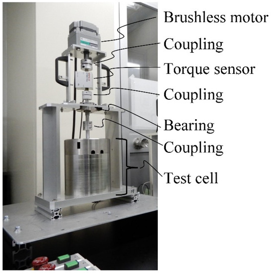
Figure 1.
Basic structure of the durability testing machine.

Table 1.
Specifications of the durability testing machine.
2.2. Rotor and Stator
We designed two sets of rotors and stators as measurement tools for the durability test machine. The first was a set of flat discs (parallel plate setting in Figure 2). This geometry is used in rheometers. Structural steel (SS400) was used in the main part of the rotor, including the shaft, such that the magnetic flux could easily pass through. A ring of nonmagnetic material (SUS316) was attached on the side surface of the rotor to prevent jumping of the magnetic particles in the MRF sample. The middle part of the stator was made of structural steel to achieve a strong magnetic flux density. Conversely, the cup was made of stainless steel to prevent littering due to centrifugal force.
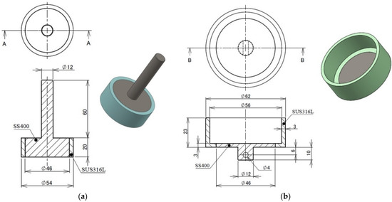
Figure 2.
Rotor and stator for the parallel plate setting. (a) Rotor, (b) stator. line A and B are the view points of the cross-sections.
The other was a set of V-shaped plates (V-shaped plate setting in Figure 3). The basic concept of this geometry was reported in [37]. This geometry has an iron-made (SS400) ring with a V-shaped convexity in the rotor and an iron-made (SS400) ring with a V-shaped concavity in the stator. The rotational shaft of the rotor and other parts are made of a nonmagnetic material (SUS316). The iron-made rings were located along the path of the magnetic flux to converge it on the MRF layers. The angle of the V-shape is 90°.
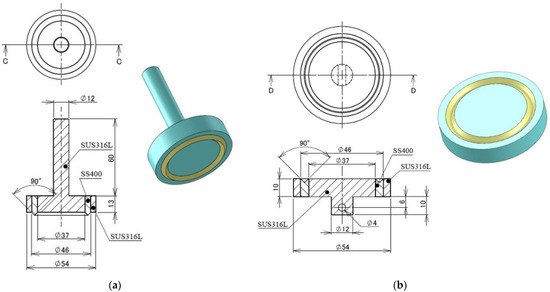
Figure 3.
Rotor and stator for the V-shaped plate setting. (a) Rotor, (b) stator. line C and D are the view points of the cross-sections.
In both cases, the MR fluid was sandwiched between the rotor and stator. The sample volume (volume of the MRF layer) was designed in the optimal calculation of the equipment design to shorten the experiment time for long-term durability tests. In the case of a parallel plate rotor, the MR fluid layer was formed over the entire range of the rotor, whereas in the case of a V-shaped rotor, the MR fluid layer was formed only in the V-shaped groove. This aids in the concentration of magnetic fields and prevents the segregation of magnetic particles.
2.3. Design of Test Cell
Figure 4 and Figure 5 show the cross sections of a parallel plate and a V-shaped rotor combined with an electromagnet, respectively. The external dimensions of the electromagnets and parameters of the coils (Table 2) were the same for both sets. In both cases, a 1 mm air gap was provided at the top of the rotor to allow measurement of the magnetic field using a Hall sensor.
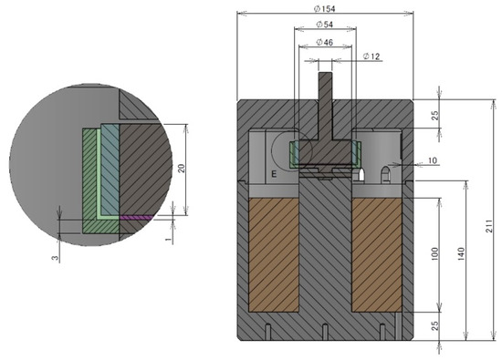
Figure 4.
Test cell for parallel plate setting. Circle E is the closeup part.
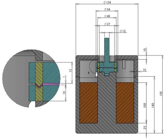
Figure 5.
Test cell for V-shaped plate setting. Circle F is the closeup part.
Table 2.
Common parameters for magnetic coil.
Magnetostatic analysis was conducted on both setups to design the electromagnets. The finite element analysis software ANSYS 2020R2 (ANSYS Inc., Canonsburg, PA, USA) was used for the analysis. Material nonlinearity was considered with the B-H curves of the core material (SS400) and MRF with 22 vol% of micron-sized Fe particles. Figure 6 shows the B-H curves. Figure 7 and Figure 8 show the magnetic flux density and direction for the parallel plate setting, and Figure 9 and Figure 10 show the magnetic flux density and direction for the V-shaped rotor at a coil current of 1 A. In the case of a parallel plate, there is leakage of magnetic flux to the shaft because the shaft is also a ferromagnetic material. However, because the shaft cross section is small, the magnetic flux saturates, and a magnetic flux density of approximately 1 T can be applied to the periphery of the plate where the MR fluid layer is located. For the V-shaped plate, a concentrated magnetic path was formed in the MR fluid layer.
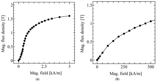
Figure 6.
B-H curves of each material. (a) SS400 (b) MRF (22 vol% of micron-sized Fe particles).
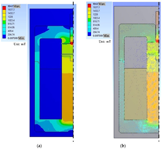
Figure 7.
Distribution of magnetic field in the parallel plate setting (full view). (a) Contour, (b) vector.
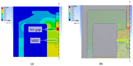
Figure 8.
Distribution of magnetic field in the parallel plate setting (fluid gap). (a) Contour, (b) vector.
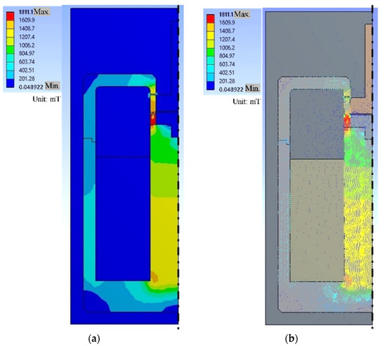
Figure 9.
Distribution of magnetic field in the V-shaped plate setting (full view). (a) Contour, (b) vector.
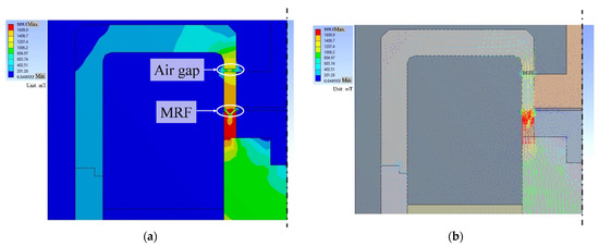
Figure 10.
Distribution of magnetic field in the V-shaped plate setting (fluid gap). (a) Contour, (b) vector.
Figure 11 shows the relationship between the coil current and the average flux density in the MR fluid layer (simulated only) and in the air gap (simulated and measured). The difference between the simulation and the measurement in the air gap is 7.8% at 1.5 A and 3.3% at 1.0 A, the beginning of the saturation, for the parallel plate setting; for the V-shaped rotor, the error is 2.7% at 1.5 A and 4.0% at 1.0 A. Although the magnetic flux density cannot be measured directly in the MR fluid layer, its error from the simulation results is several percentages at 1.0 A.
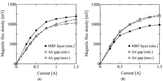
Figure 11.
Analytic results on current vs. magnetic field. (a) Parallel plate, (b) V-shaped plate.
Comparing the magnetic flux flow in the two rotors, the magnetic flux density in the air gap was smaller than that in the MR fluid layer owing to the flux leakage in the parallel plate structure. In contrast, in the V-shaped rotor, the magnetic flux density in the MR fluid layer is smaller than that in the air gap because the cross-sectional area of the MR fluid layer formed by the V-groove is larger than that of the parallel surfaces of the air gap. However, the magnetic flux leakage was small, and a magnetic flux density of approximately 1 T could be achieved for a current of 1 A.
3. Validation of Durability Test Device
3.1. Method
To verify the performance of the developed device, measurements of the torque characteristics when a magnetic field was applied to a sample MR fluid were conducted. Table 3 lists the properties of the standard materials. The fluid gap was set to 1 mm, as described in Section 2. The fluid volume was 1.66 mL for the parallel plate setting and 0.59 mL for the V-shaped plate setting. The measured torque was converted to a value per unit volume for normalization.
Table 3.
Properties of the standard material.
Figure 12 shows the MR properties of the sample material (horizontal axis: applied flux density; vertical axis: yield shear stress). Measurements were conducted using a rheometer (HAAKE RheoStress 6000, Thermo Fisher Scientific, Waltham, MA, USA) at a shear rate of 100 s−1 and a measurement temperature of 25 °C. The rotor was a parallel plate with a diameter of 20 mm.
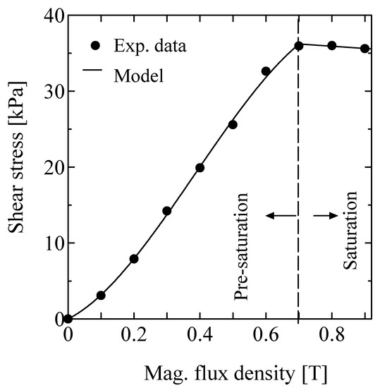
Figure 12.
Flow characteristics of the sample material.
The plots in Figure 11 show the shear stress measured by the rheometer, which increased rapidly up to a flux density of 0.7 T and decreased slightly after 0.7 T. Therefore, this property was divided into pre-saturation and saturation, and each was modeled (solid lines in Figure 11). In the pre-saturation region, the shear stress (kPa) is approximated by a third-order polynomial function of the magnetic flux density B (T) using the least squares method, as shown in the first equation of Equation (1). After saturation, the line was approximated using the second equation of Equation (1) as a straight line, continuous with the pre-saturation curve.
3.2. Result
The measurement results for both plates are shown in Figure 13. The horizontal axis shows the coil current, and the vertical axis shows the resistive torque owing to the MR fluid. The circles represent the simulation results and the triangles represent the measured values.
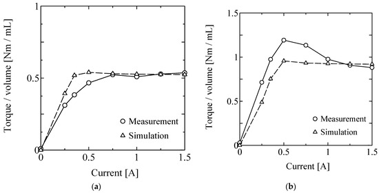
Figure 13.
Torque estimation and measurement for the sample 1 (Micron MRF). (a) Parallel plate, (b) V-shaped plate.
For the parallel plate, the simulation torque, T, was estimated using Equation (2), where the inner and outer radii of the MRF layer are (= 23 mm) and (=6 mm), respectively. Because the magnetic flux density only varied approximately 0.1% within this range, τ was also considered constant in the radius.
However, for the V-shaped rotor, the integrating area of the MRF layer was turned back, as shown in Figure 14, and the estimated torque was calculated using Equation (3), where b is the limit of the integrating area on the x-axis x as shown in Equation (4), and A, estimated as 0.5, is the contribution ratio of the edge effect.
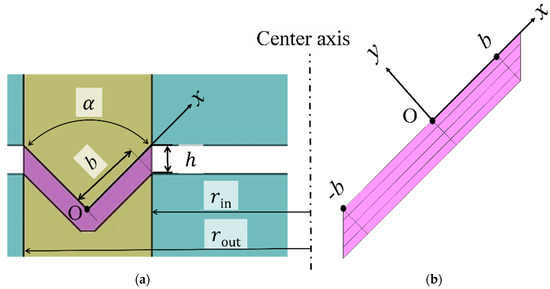
Figure 14.
Definition of integration area for V-shaped plate. (a) Parameters, (b) integration area after turnback.
3.3. Discussion
Comparing the torque per unit volume, the parallel plate has a torque of approximately 0.5 Nm/mL when 1 A is applied, while the V-shaped rotor has a torque of approximately 1.0 Nm/mL. This is because the test sample existed only near the outer circumference of the disk, and the magnetic flux was applied in a concentrated manner for the V-shaped rotor. This allows for efficient and uniform testing when the device is used as the testing machine.
For the parallel plate case, the measured torque is lower than the predicted value, especially at approximately 0.5 A. In contrast, the V-shaped disk exhibits a larger torque than the estimated value at approximately 0.5 A. The fluid characteristics in Figure 11 are based on a standard rheometer with a parallel plate rotor and do not consider the characteristics of the V-shaped disk. This phenomenon cannot be explained by macroscopic characteristics and is thought to be caused by unique phenomena, such as the particle arrangement when a V-shaped disk is used. This should be verified in future studies.
4. Long-Term Measurement
4.1. Method
The objective was to perform long-term measurements of MRFs using the developed durability test apparatus and to compare the results. Two types of MRFs, as shown in Table 4, were used in the experiment; the micron MRFs were identical to the standard materials shown in Table 3. These two materials were synthesized primarily to evaluate the effects of particle size differences. For the parallel plate setting, the coil current was set to 0.250 A for the micron MRF (374 mT) and 0.350 A for the nano MRF (500 mT). The V-shaped rotor was set to 0.224 A for the micron MRF (367 mT) and 0.304 A for the nano MRF (500 mT). These values were determined to generate approximately the same torque for each rotor setting. The rotation speed was 200 rpm for all the conditions. All experiments were conducted under a room temperature (20 °C) with thermal control. Though the local temperature in the MRF layer was not directly measured, temperature elevation was not determined outside the test cell.
Table 4.
Properties of the standard materials.
4.2. Result
The experimental results are shown in Figure 15. The horizontal and vertical axes show the LDE in MJ/mL and the measured torque per unit volume, respectively. The LDE was calculated from the integration of the multiplication of the measured torque, rotational velocity, and sampling time of the measurement. The LDE results for the V-shaped rotor were relatively short. The values for micron-scale MRF were also relatively short. In addition, the variations in the torque were relatively large for the micron MRF.
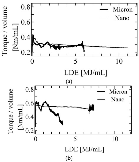
Figure 15.
Torque profile in the long-term measurement. (a) Parallel plate, (b) V-shaped plate.
4.3. Discussion
As shown in the Figure 15, the torque of the micron MRF for the parallel plate setting significantly varied during the whole range of the test, and suddenly dropped at around 6 MJ/mL. On the other hand, the torque of the nano MRF for the parallel plate setting shows a variation until around 1 MJ/mL, and is significantly stable after that. This trend is similar for the V-shaped plate setting. However, there are some differences. The torque variation for the nano MRF is slightly smaller than that for the parallel plate. In addition, the LDEs are significantly shorter than those for the parallel plate for both materials.
To evaluate the variation in torque, the average and standard deviation of the torque from 1 MJ/mL to 2 MJ/mL are summarized in Table 5. The variation in the nano MRF is significantly smaller for both the parallel and V-shaped plates.
Table 5.
Summary of the long-term measurement.
As mentioned in the introduction, Gabriel et al. [33] investigated the mechanical durability of MRF and found the LDE to be 5 MJ/mL. The result by Wiehe et al. [34] was 6 MJ/mL. The result of the micron MRF for the parallel plate setting was the same as that of the conventional values. However, the result of the nano MRF for the parallel plate is at least double the duration of the micron MRF. The duration of the nano MRF was significantly longer than that of the conventional MRF.
The duration of both MRFs for the V-shaped plate was much shorter than that for the parallel plate. The reason for the long durability of the parallel plate rotor may spring from the unexpected particle migration from the center area of the disk (Figure 16a); with the V-shaped rotor, the test particles do not migrate from the periphery (Figure 16b), and, thus, the aging of the fluid can be fairly evaluated. In addition, the V-shaped rotor exhibited relatively higher shear stress than the parallel plate rotor, and we believe that there was a difference in the cluster structure of the particles. The area near the apex of the V-shaped rotor is a geometrical region that does not exist in the parallel plate, and it is predicted that a peculiar particle structure is formed. In this analysis, only a macroscopic viewpoint was observed. Further microscopic observations will be necessary in the future.
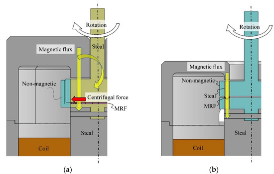
Figure 16.
Difference between the parallel plate setting and V-shaped plate setting. (a) Parallel plate, (b) V-shaped plate.
5. Conclusions
In this study, we developed durability test equipment for MRFs with two sets of rotors and stators to evaluate the effect of the V-shaped MRF layer. Magnetostatic analyses were performed to design an electric magnet as a test cell for the durability test device. Validation tests of the developed durability machine were conducted for an MRF with micron-sized Fe particles. According to the magnetic measurement and torque tests, for the parallel plate case, the measured torque is lower than the predicted value, especially at approximately 0.5 A. In contrast, the V-shaped disk exhibited a larger torque than estimated at approximately 0.5 A. Durability tests for two types of the MRF (the nano MRF and micron MRF) with two types of the rotor were conducted. The torque variation for the nano MRF is significantly smaller for both the parallel and V-shaped plates. In addition, the duration of both MRFs for the V-shaped plate was much shorter than that for the parallel plate. Particle migration is one possible reason for these differences. Therefore, the V-shaped rotor has the potential to evaluate the durability of MRFs fairly. In addition, the V-shaped rotor exhibited relatively higher shear stress than that of the parallel plate rotor. Further microscopic observations will be necessary in the future.
Author Contributions
Conceptualization, T.K., Y.U. and S.A.; methodology, T.K. and Y.U.; investigation, T.K.; mechanical design, S.A., H.T. and I.A.; writing—original draft preparation, T.K. and Y.U.; writing—review and editing, T.K.; visualization, T.K. and I.A.; supervision, T.K.; project administration, T.K.; funding acquisition, T.K. All authors have read and agreed to the published version of the manuscript.
Funding
This research was partially supported by the Adaptable and Seamless Technology Transfer Program through target-driven R&D of the Japan Science and Technology Agency (JST), JPMJTM20HM.
Informed Consent Statement
Not applicable.
Conflicts of Interest
The authors declare no conflict of interest.
References
- Carlson, J.D.; Jolly, M.R. MR fluid foam and elastomer devices. Mechatronics 2000, 10, 555–569. [Google Scholar] [CrossRef]
- Junichi, N.; Hiroya, A.; Takehito, K.; Junji, F.; Makio, N. Magnetorheology of colloidal dispersion containing Fe nanoparticles synthesized by the arc-plasma method. J. Magnet. Magnet. Mater. 2010, 322, 1868–1871. [Google Scholar]
- Il, J.M.; Min, W.K.; Hyong, J.C.; Namhui, K.; Chun-Yeol, Y. Fabrication of dopamine grafted polyaniline/carbonyl iron core-shelltyped microspheres and their magnetorheology. Colloids Surf. A Physicochem. Eng. Asp. 2016, 500, 137–145. [Google Scholar]
- Goncalves, F.; Carlson, J. Investigating the time dependence of the MR effect. Int. J. Mod. Phys. B 2007, 21, 4832–4840. [Google Scholar] [CrossRef]
- Kubík, M.; Šebesta, K.; Strecker, Z.; Jeniš, F.; Goldasz, J.; Mazůrek, I. Hydrodynamic response time of magnetorheological fluid in valve mode: Model and experimental verification. Smart Mater. Struct. 2021, 30, 125020. [Google Scholar] [CrossRef]
- Kwok, N.M.; Ha, Q.P.; Nguyen, M.T.; Li, J.; Samali, B. Bouc–Wen model parameter identification for an MR fluid damper using computationally efficient GA. ISA Trans. 2007, 46, 167–179. [Google Scholar] [CrossRef]
- Yazid, I.; Mazlan, S.; Imaduddin, F.; Zamzuri, H.; Choi, S.-B.; Kikuchi, T. An investigation on the mitigation of end-stop impacts in a magnetorheological damper operated by the mixed mode. Smart Mater. Struct. 2016, 25, 125005. [Google Scholar] [CrossRef]
- Choi, S.; Hong, S.; Cheong, C.; Park, Y. Comparison of field-controlled characteristics between ER and MR clutches. J. Intell. Mater. Syst. Struct. 1999, 10, 615–619. [Google Scholar] [CrossRef]
- Lee, U.; Kim, D.; Hur, N.; Jeon, D. Design analysis and experimental evaluation of an MR fluid clutch. J. Intell. Mater. Syst. Struct. 1999, 10, 701–707. [Google Scholar] [CrossRef]
- Kavlicoglu, B.; Gordaninejad, F.; Evrensel, C.; Liu, Y.; Kavlicoglu, N.; Fuchs, A. Heating of a high-torque magnetorheological fluid limited slip differential clutch. J. Intell. Mater. Syst. Struct. 2008, 19, 5–241. [Google Scholar] [CrossRef]
- Kikuchi, T.; Otsuki, K.; Furusho, J.; Abe, H.; Noma, J.; Naito, M.; Lauzier, N. Development of compact MR fluid clutch for human-friendly actuator. Adv. Robot. 2010, 24, 1489–1502. [Google Scholar] [CrossRef]
- Takehito, K.; Isao, A. Low inertia torque controllable device using magnetorheological fluid & umbrella-shaped rotor. Eng. Res. Exp. 2019, 1, 02502. [Google Scholar] [CrossRef]
- Tsujita, T.; Ohara, M.; Sase, K.; Konno, A.; Nakayama, M.; Abe, K.; Uchiyama, M. Development of a haptic interface using mr fluid for displaying cutting forces of soft tissues. In Proceedings of the 2012 IEEE International Conference on Robotics and Automation, Saint Paul, MN, USA, 14–18 May 2012; pp. 1044–1049. [Google Scholar]
- Fukuda, M.; Suzuki, Y. Elasticity Detection and Display of a Grasped Object Using Master-Slave System. In Proceedings of the 2012 SICE Annual Conference, Akita, Japan, 20–23 August 2012; pp. 1758–1762. [Google Scholar]
- Song, B.-K.; Oh, J.-S.; Choi, S.-B. Design of new 4-DOF haptic master featuring magnetorheological fluid. Adv. Mech. Eng. 2014, 6, 843498. [Google Scholar] [CrossRef] [Green Version]
- Takehito, K.; Junichi, N.; Syuichi, A.; Yuya, U. Response time of magnetorheological fluid-based haptic device. J. Intell. Mater. Syst. Struct. 2015, 27, 859–865. [Google Scholar] [CrossRef]
- Takehito, K.; Isao, A.; Tomoya, N.; Akinori, Y.; Tetsumasa, T. Twin-Driven actuator with multi-layered disc MR fluid clutches for haptics. J. Intell. Mater. Syst. Struct. 2021, 32, 1326–1335. [Google Scholar] [CrossRef]
- Takehito, K.; Tetsumasa, T.; Akinori, Y.; Asaka, I.; Isao, A. Haptic interface with twin-driven MR fluid actuator for teleoperation endoscopic surgery system. Actuator 2021, 10, 245. [Google Scholar] [CrossRef]
- Nishida, H.; Shimada, K.; Ido, Y. Effectiveness of using a magnetic compound fluid with a pulsed magnetic field for flat surface polishing. Int. J. Appl. Electromagnet. Mech. 2012, 39, 623–628. [Google Scholar] [CrossRef]
- Kordonskii, V.I.; Gorodkin, S.R. Magnetorheological polishing of optical surfaces. J. Opt. Technol. 2012, 79, 588. [Google Scholar] [CrossRef]
- Chaudhuri, A.; Wang, G.; Wereley, N.M.; Tasovksi, V.; Radhakrishnan, R. Substitution of micron by nanometer scale powders in magnetorheological fluids. Int. J. Mod. Phys. B 2005, 19, 1374–1380. [Google Scholar] [CrossRef]
- Wei, J.H.; Leng, C.J.; Zhang, X.Z.; Li, W.H.Z.; Liu, Y.; Shi, J. Synthesis and magnetorheological effect of Fe3O4-TiO2 nanocomposite. J. Phys. Conf. Ser. 2009, 149, 012083. [Google Scholar] [CrossRef] [Green Version]
- Park, B.J.; Park, C.W.; Yang, S.W.; Kim, H.M.; Choi, H.J. Core-shell typed polymer coated-carbonyl iron suspensions and their magnetorheology. J. Phys. Conf. Ser. 2009, 149, 012078. [Google Scholar] [CrossRef] [Green Version]
- Becnel, A.C.; Hu, W.; Wereley, N.M. High shear rate characterization of magnetorheological fluids. In Active and Passive Smart Structures and Integrated Systems 2012; International Society for Optics and Photonics: Bellingham, WA, USA, 2012. [Google Scholar]
- Xiaojie, W.; Faramarz, G. Study of magnetorheological fluids at high shear rates. Rheol. Acta 2006, 45, 899–908. [Google Scholar]
- Becnel, A.C.; Sherman, S.; Hu, W.; Wereley, N.M. Nondimensional scaling of magnetorheological rotary shear mode devices using the mason number. J. Magnet. Magnet. Mater. 2015, 380, 90–97. [Google Scholar] [CrossRef]
- Kikuchi, T.; Abe, I.; Inoue, A.; Iwasaki, A.; Okada, K. Characteristics of a magnetorheological fluid in high shear rate. Smart. Mater. Struct. 2016, 25, 115021. [Google Scholar] [CrossRef]
- Takesue, N.; Furusho, J.; Kiyota, Y. Fast response MR-fluid actuator. JSME Int. J. Ser. C 2004, 47, 783–791. [Google Scholar] [CrossRef] [Green Version]
- Kikuchi, T.; Furusho, J.; Yamaguchi, Y.; Kimura, S. Design of the High-Performance MR Brake and its Characteristics. In Proceedings of the 10th International Conference on ER Fluids and MR Suspensions, Lake Tahoe, USA, 18–22 June 2006; pp. 667–673. [Google Scholar]
- Wereley, N.M.; Chaudhuri, A.; Yoo, J.H.; John, S.; Kotha, S.; Suggs, A.; Radhakrishnan, R.; Love, B.J.; Sudarshan, T.S. Bidisperse magnetorheological fluids using Fe particles at nanometer and micron scale. J. Intell. Mater. Syst. Struct. 2006, 17, 393–401. [Google Scholar] [CrossRef]
- Hou, P.; Zhang, Q.J.; Wereley, N.M. Effect of storage and ball milling on the sedimentation and rheology of a novel magnetorheological fluid. J. Phys. Confer. Ser. 2009, 149, 012043. [Google Scholar]
- Carlos, G.S.; Tania, L.C.; Enrique, J.R.; Mircea, R.; Ulrich, S.S. Magnetorheological fluids based on ionic liquids. Adv. Mater. 2011, 20, 045001. [Google Scholar]
- Gabriel, C.; Oetter, G.; Kieburg, C.; Laun, M. Durability testing on magnetorheological fluids for clutch and brake applications. In Proceedings of the 12th International Conference on ER Fluids and MR Suspensions, Philadelphia, PA, USA, 16–20 August 2010; pp. 605–611. [Google Scholar]
- Carlson, J.D. What makes a good MR fluid? J. Intell. Mater. Syst. Struct. 2002, 13, 431–435. [Google Scholar] [CrossRef]
- Bigué, J.P.; Landry-Blais, A.; Pin, A.; Pilon, R.; Plante, J.S.; Chen, X.; Andrews, M. On the relation between the Mason number and the durability of MR fluids. Smart Mater. Struct. 2019, 28, 094003. [Google Scholar] [CrossRef]
- Ansgar, W.; Jurgen, M. Large-scale test bench for the durability analysis of magnetorheological fluids. J. Intell. Mater. Syst. Struct. 2012, 24, 1433–1444. [Google Scholar]
- Ulicny, J.C.; Balogh, M.P.; Potter, N.M.; Waldo, R.A. Magnetorheological fluid durability test–Iron analysis. Mater. Sci. Eng. A 2007, 443, 16–24. [Google Scholar] [CrossRef]
- Ulicny, J.C.; Hayden, C.A.; Hanley, P.M.; Eckel, D.F. Magnetorheological fluid durability test–Organics analysis. Mater. Sci. Eng. A 2007, 464, 269–273. [Google Scholar] [CrossRef]
- Isao, A.; Takehito, K.; Junichi, N. Durability test device for MR fluids with permanent magnet & V-shaped groove. Smart. Mater. Struct. 2017, 26, 054004. [Google Scholar] [CrossRef]
Publisher’s Note: MDPI stays neutral with regard to jurisdictional claims in published maps and institutional affiliations. |
© 2022 by the authors. Licensee MDPI, Basel, Switzerland. This article is an open access article distributed under the terms and conditions of the Creative Commons Attribution (CC BY) license (https://creativecommons.org/licenses/by/4.0/).