Abstract
Pneumatic soft grippers have been widely studied. However, the structures and material properties of existing pneumatic soft grippers limit their load capacity and manipulation range. In this article, inspired by sea lampreys, we present a pneumatic novel combined soft gripper to achieve a high load capacity and a large grasping range. This soft gripper consists of a cylindrical soft actuator and a detachable sucker. Three internal air chambers of the cylindrical soft actuator are inflated, which enables them to hold objects. Under vacuum pressure, the cylindrical soft actuator and the detachable sucker can both adsorb objects. A finite element model was constructed to simulate three inflation chambers for predicting the grasping range of the cylindrical soft actuator. The validity of the finite element model was established by an experiment. The mechanism of holding force and adsorption force were analyzed. Several groups of experiments were conducted to determine adsorption range, holding force, and adsorption force. In addition, practical applications further indicated that the novel combined soft gripper has a high load capacity (10.85 kg) at a low pressure (16 kPa) and a large grasping range (minimum diameter of the object: d = 6 mm), being able to lift a variety of objects with different weights, material properties, and shapes.
1. Introduction
Soft robots have distinguishable potential and advantages compared to traditional rigid robots, such as flexibility, high environmental adaptability, shock-absorbing properties, and high degrees of freedom, and therefore, the application areas of soft robots have involved human–machine interaction, locomotion and exploration, manipulation, medical and surgical applications, rehabilitation, and wearable robots [1,2,3,4]. Soft robotic grippers are one of the research areas in the field of soft robots. Scholars have created various soft robotic grippers with different drive modes [5,6,7], including pneumatic actuation [8,9,10,11], cable-driven actuation [12], shape memory alloys actuation [13,14,15], and electroactive polymers actuation [16,17,18]. Pneumatic actuation has been widely studied due to its advantages of a large driving force, a fast response speed, and convenient and safe gas source acquisition.
Load capacity and grasping range are two key indicators used to evaluate the performance of soft robot grippers. A pneumatic multi-finger soft gripper can adjust its shape according to the shape of the object to grasp objects with different sizes and shapes [19,20,21,22,23,24,25,26,27,28]. Fiber-reinforced actuators [29,30], granular jamming actuators [31,32,33] and bellows-type actuators [34] are used to improve the load force of multi-finger soft grippers. A multi-finger soft gripper is capable of lifting an object weighing 5 kg [35]. However, due to the opened structure and the low stiffness, multi-finger soft grippers can only exhibit low load capacity. Closed structure soft grippers utilize granular jamming to grasp objects. The load capacity of the universal soft robotic grippers based on the jamming of granular material reaches 8 kg [36,37,38]. However, the fluidity and arrangement uncertainty of the granules cause instability of stiffness in closed structure soft grippers, which limits the increase in the load force of the closed structure soft gripper. Ring-shaped soft robotic grippers allow for grasping objects through radial shrinkage deformation [39,40]. The load force of the bionic winding soft robotic gripper reaches 10.5 kg [41], which achieves high load capacity. However, the grasping range of the ring-shaped soft gripper is limited, and the objects whose size exceeds the inner diameter of the ring-shaped soft gripper cannot be grasped.
In this work, inspired by sea lampreys, we propose a pneumatic novel combined soft gripper that is composed of a cylindrical soft actuator and a detachable sucker. The cylindrical soft actuator has a grasping function and an adsorption function, and the detachable sucker has an adsorption function. The experiments and applications of grasping and adsorption objects with different weights, sizes and materials indicate that the novel combined soft gripper has a high load capacity and a large grasping range. This novel combined soft gripper fills the defect of the existing soft grippers and provides a new idea for the structure design of the soft gripper in the future.
This paper is organized as follows: first, the design concept and structure of the novel combined soft gripper are described. Then, the fabrication process of the novel combined soft gripper is illustrated. Furthermore, a finite element model and a series of experiments and applications are conducted to validate that the novel combined soft gripper has a high load capacity and a large grasping range. The last section presents the discussion and conclusion.
2. Materials and Methods
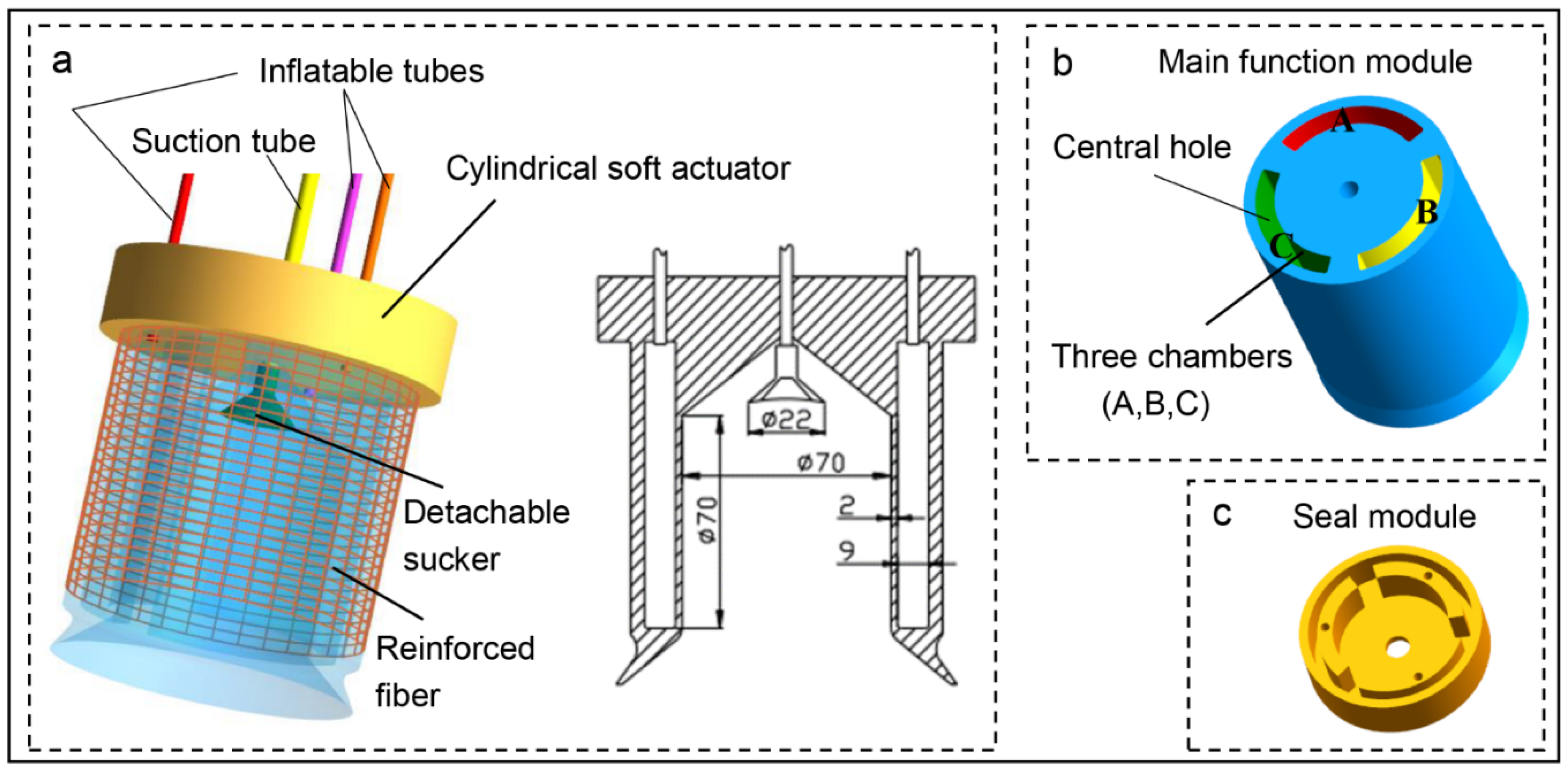
2.1. Design Concept and Structure of the Novel Combined Soft Gripper
Sea lampreys have suction-cup mouths that are strengthened by annular cartilage [42,43]. The sea lamprey can seize stones with its suction-cup mouth (Figure 1a) and can attach to the body of its victim by means of its suction-cup mouth, with its sharp teeth rasping a hole in the body for sucking blood (Figure 1b). A sea lamprey’s mouth is shown in Figure 1c. The adsorption and seizing behavior of sea lampreys inspired us to fabricate a novel combined soft gripper that has grasping and adsorption functions.
Figure 1.
The sea lampreys. (a) A sea lamprey seizes stones with its suction-cup mouth. (b) A sea lamprey attaches to the body of a fish by its suction-cup mouth. (c) A sea lamprey’s mouth.
As shown in Figure 2, this novel combined soft gripper consists of a cylindrical soft actuator and a detachable sucker (Figure 2a). The cylindrical soft actuator consists of a main function module and a seal module (Figure 2b,c). The inflatable tubes connect the cylindrical soft actuator with an air compressor. The suction tube connects the novel combined soft gripper with a vacuum pump. When the air chambers of the cylindrical soft actuator are inflated, the inner and outer walls of the cylindrical soft actuator expand radially, although the expansion of the outer wall could affect the grasping force of the cylindrical soft actuator, which is undesirable. Therefore, we use reinforced fibers to prevent radial expansion of the outer wall of the cylindrical soft actuator under input air pressure.
Figure 2.
Structure of the novel combined soft gripper. (a) The novel combined soft gripper consists of a cylindrical soft actuator and a detachable sucker. (b) Structure of the main function module. (c) Structure of the seal module.
As shown in Figure 3. Under the action of the air compressor, the air chambers of the cylindrical soft actuator inflate to grasp the object (Figure 3a,b). Under the action of the vacuum pump, the cylindrical soft actuator acts as a suction cup to absorb the object (Figure 3c,d).
Figure 3.
Schematic of the working principle of the novel combined soft gripper. (a) Schematic of grasping and holding of the cylindrical soft actuator. (b) Holding force analysis. (c) Schematic of adsorption of the cylindrical soft actuator. (d) Adsorption force analysis. (e) Schematic of adsorption of the detachable sucker.
Taking the center of gravity of the object as the coordinate origin, the coordinate system when the object is placed on the horizontal plane is G0 = {O, x0, y0, z0}, and the new coordinate system obtained by the coordinate rotation Formula (1) is G1 = {O, x1, y1, z1}.
where respectively, represent the angle between coordinate system G0 and coordinate system G1.
The gravity vector of the object in the coordinate system is . The gravity vector of the object in the coordinate system is expressed as:
The cylindrical soft actuator holds the object to maintain balance on the x, y, and z axis (Figure 3a,b). From the balance expression on the z-axis, the holding force is obtained:
Regarding the cylindrical soft actuator and the object as a rigid body, the torque of the rigid body relative to the fixed end of the cylindrical soft actuator is expressed as follows:
where is the total normal force, is the static friction coefficient between the cylindrical soft actuator and the object, and H is the distance between the center of gravity of rigid body and the fixed end of the cylindrical soft actuator.
When the cylindrical soft actuator absorbs the object to maintain balance (Figure 3c,d), the required adsorption force and the torque are expressed as follows:
where is the static friction coefficient between the cylindrical soft actuator and the object, and is the length of the cylindrical soft actuator.
The adsorption principle of the detachable sucker (Figure 3e) is the same as that of the cylindrical soft actuator.
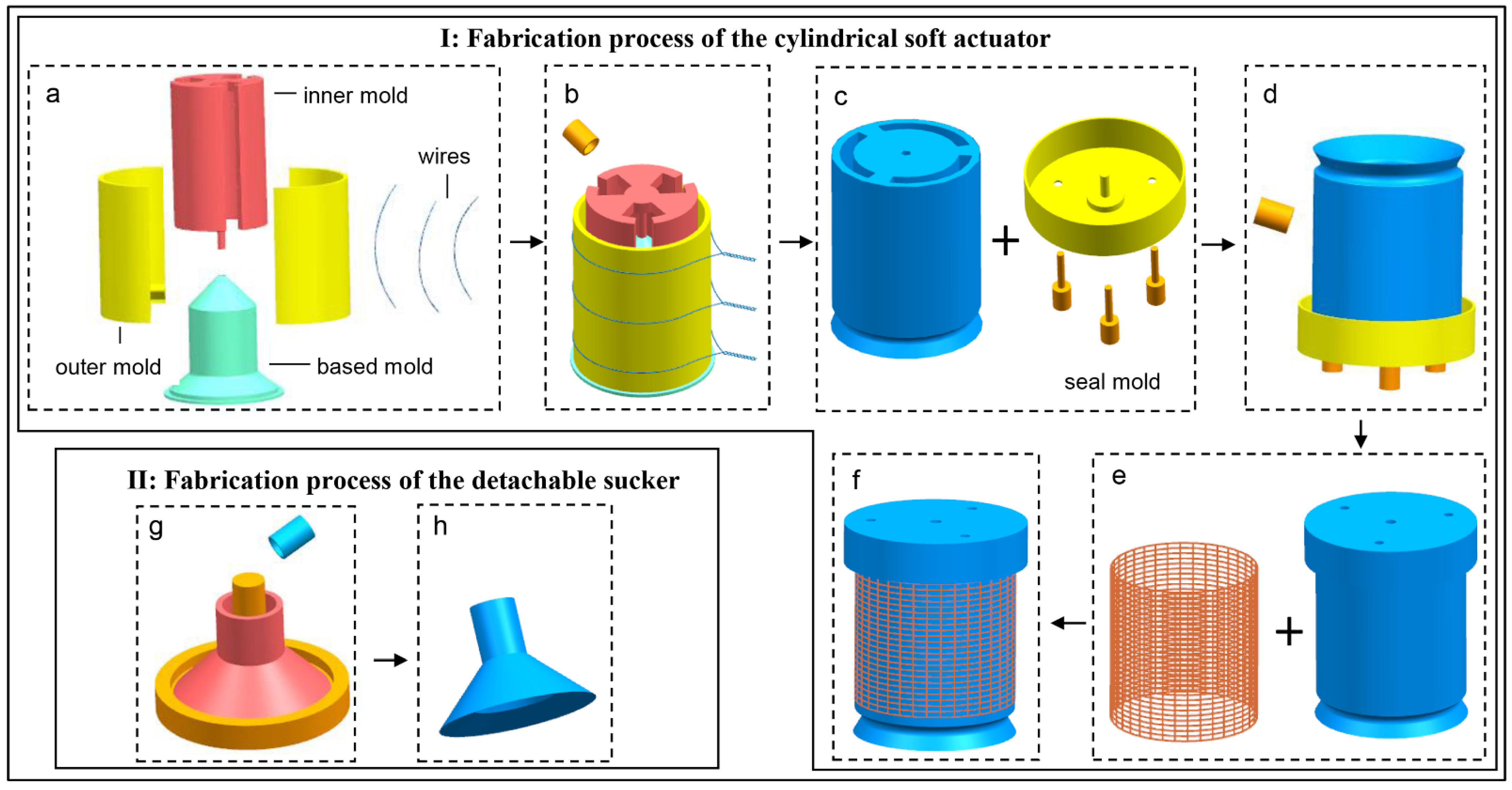
2.2. Fabrication of the Novel Combined Soft Gripper
The novel combined soft gripper was fabricated by the casting molding method, and all the molds utilized in this fabrication method were 3D printed (Creality 3D CR-2020, Shenzhen Creality 3D Technology Co., Ltd., Shenzhen, China) with PLA materials. As illustrated in Figure 4, the fabrication process can be presented as follows:
Figure 4.
Fabrication process of the novel combined soft gripper. (I) Fabrication of the cylindrical soft actuator: (a,b) Based mold, two outer molds and inner mold were used to cast the main function module, (c,d) main function module and seal mold were used to cast the seal module. (e,f) Reinforced fiber covered the outer wall of the main function module, and then the cylindrical soft actuator formed. (II) Fabrication of the detachable sucker: (g) 3D printed molds were used to cast the detachable sucker. (h) The cured detachable sucker.
Casting main function module: The fabrication process of the main function module is shown in Figure 4(Ia–c). Firstly, the based mold and two outer molds were assembled together with three wires. Then, the inner mold was mounted on the based mold. Lastly, the liquid silicone (E630, Shenzhen Hongyejie Technology Co., Ltd., Shenzhen, China) was poured into the assembled molds and then demolded after the silicone cured.
Casting seal module: The seal module was casted on the closed end of the main function module to seal the three air chambers (A, B, and C). As shown in Figure 4(Id–f), the main function module was fixed on the seal mold. The liquid silicone was poured into the seal mold, and then demolded after curing, and the seal module and the main function module formed a whole. Reinforced fiber covered the outer wall of the cylindrical soft actuator.
Casting detachable sucker: As illustrated in Figure 4II, the liquid silicone was poured into the assembled molds, and then demolded after the silicone cured.
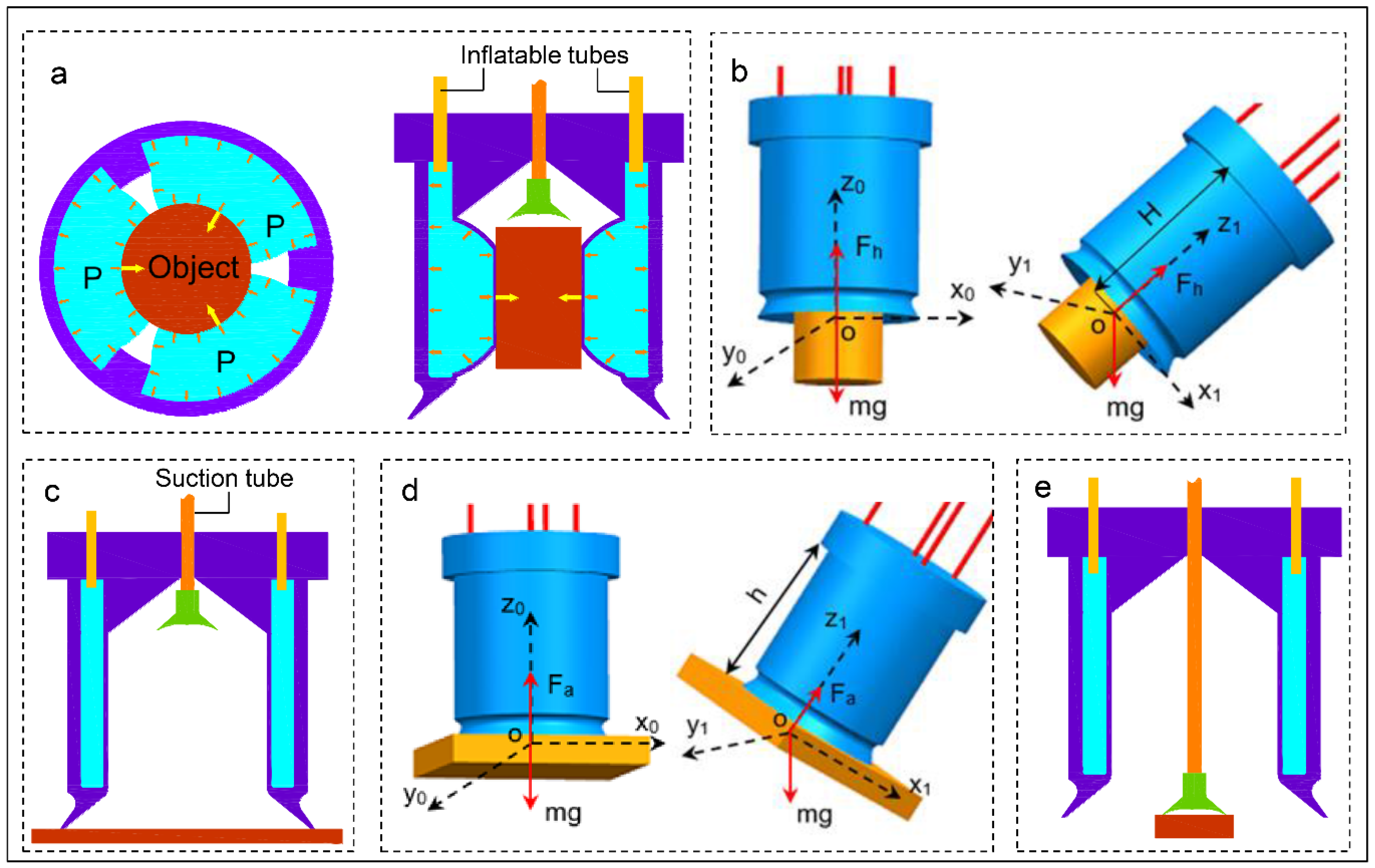
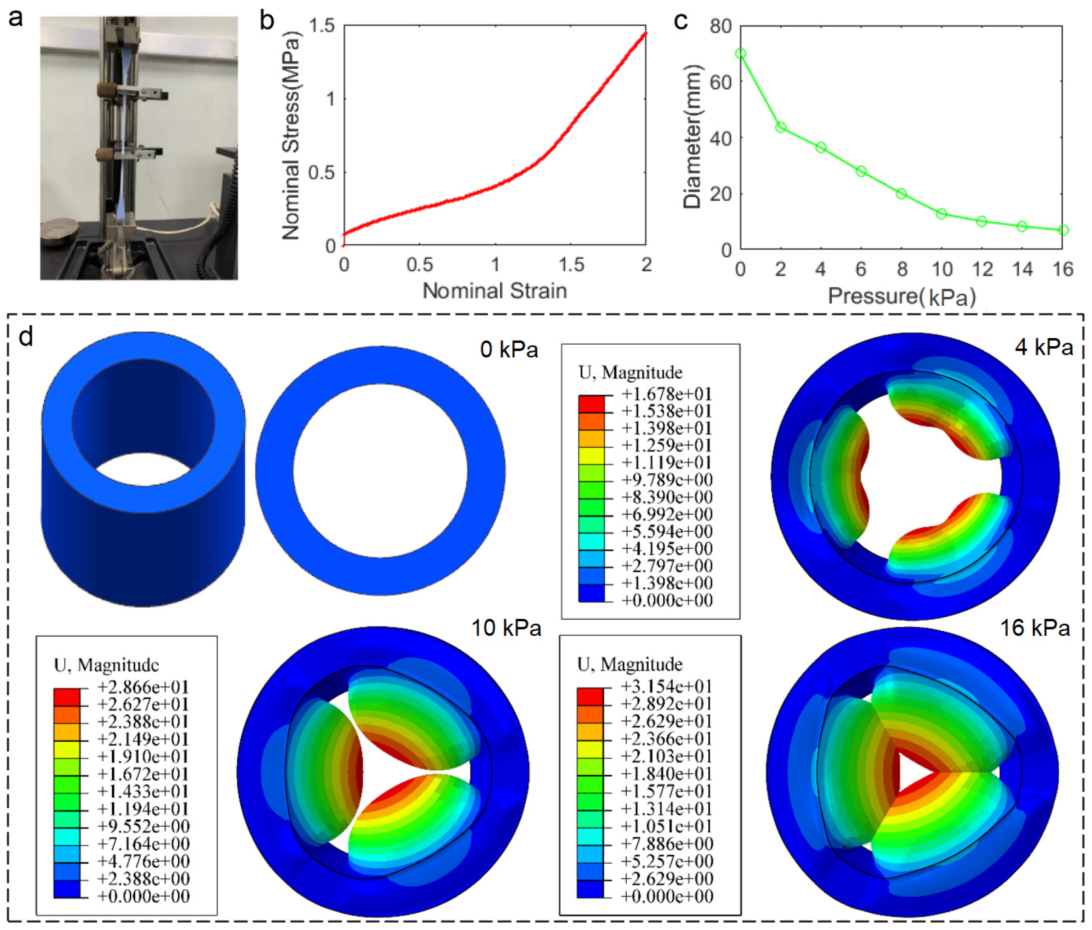
2.3. Finite Element Method Modeling
Uniaxial tensile tests of the dumbbell specimens were conducted following the ISO 37 standard using a universal tester (Model: CMT4203; MTS SYSTEMS CO., Ltd., Hangzhou, China) (Figure 5a). The averaged nominal stress-strain date is shown in Figure 5b.
Figure 5.
(a) Uniaxial tensile tests. (b) The averaged nominal stress-strain curve of dumbbell specimens. (c) The relationship between inscribed circle diameters and input air pressures of finite element simulation. (d) The inflated state of finite element model at 0 kPa, 4 kPa, 10 kPa, and 16 kPa respectively.
To predict the grasping range of the cylindrical soft actuator, a finite element model was developed and analyzed using ABAQUS/Standard (Dassault Systemes Simulia Corp.). The Yeoh (C10 = 0.2364, C20 = −0.3033, C30 = 0.2481) model was used to characterize the material response. The constraint of zero radial displacement was applied to the outer wall of the cylindrical soft actuator to replace the role of the reinforced fiber. We simplified the finite element model for realizing simulation and improving computational efficiency, and ignored the air tubes. The input air pressure (varying from 0 to 16 kPa at 2 kPa intervals) acted on the walls of three internal air chambers. The relationship between the inscribed circle diameters and input air pressures is shown in Figure 5c. The inflated state of the finite element model at 0, 4, 10, and 16 kPa, respectively, is illustrated in Figure 5d.
3. Results
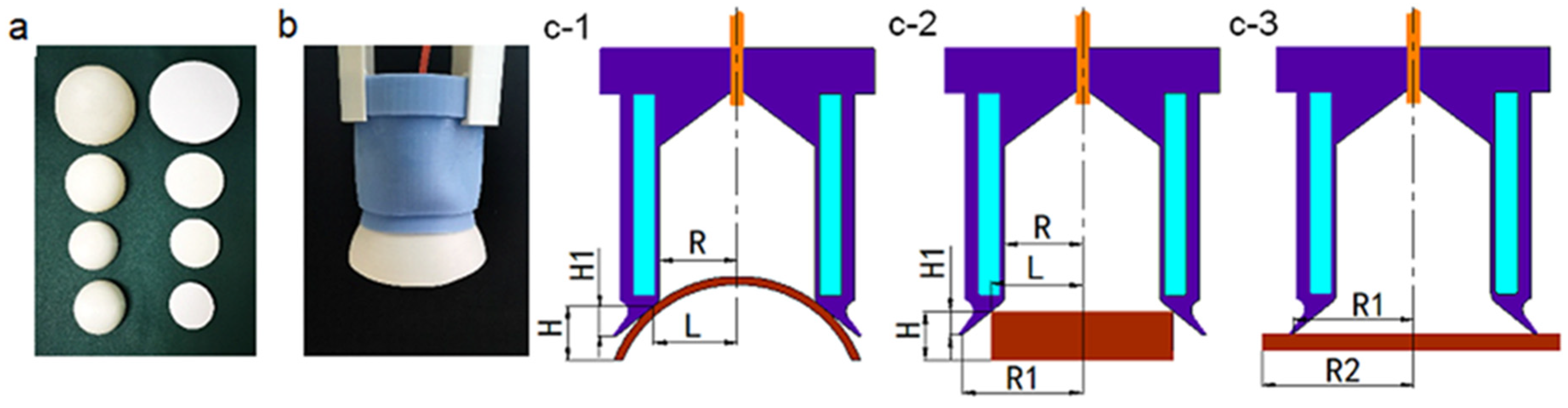
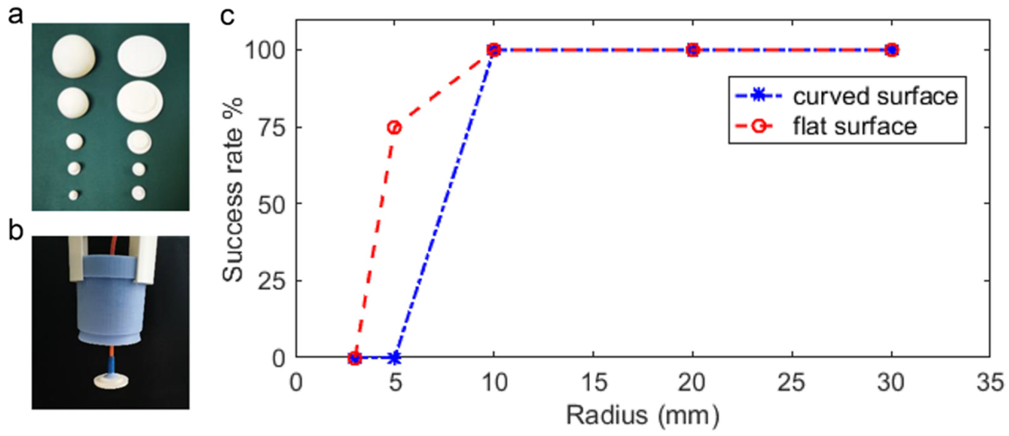
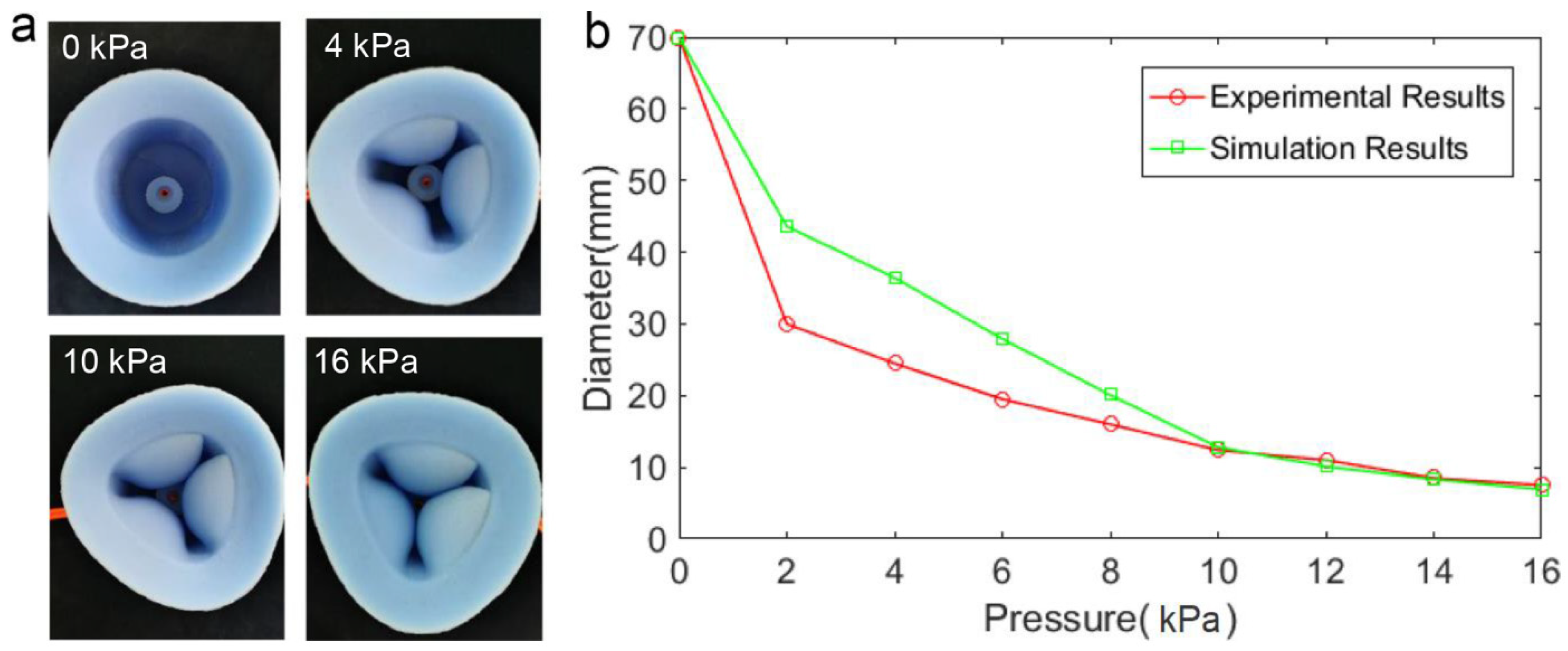
3.1. Grasping Range of the Cylindrical Soft Actuator
To determine the grasping range of the cylindrical soft actuator, we measured the inscribed circle diameter under pressures from 0 to 16 kPa at 2 kPa intervals of the cylindrical soft actuator using a conical bore gauge (Conical bore gauge, Shan Ce Instrument Co., Ltd., Beijing, China). The experimental results show that the inscribed circle diameter changed from 70 to 7.5 mm, which provides the basis for the following selection of sizes of experiment objects. The inflated state of the cylindrical soft actuator at 0, 4, 10 and 16 kPa, respectively, can be observed in Figure 6a. As depicted in Figure 6b, simulation results and experimental results show the same trend, and the simulation results are in good agreement with the experimental results. Therefore, this finite element model can predict the general grasping range of the cylindrical soft actuator.
Figure 6.
Grasping range of the cylindrical soft actuator. (a) The inflated state of the cylindrical soft actuator at 0 kPa, 4 kPa, 10 kPa and 16 kPa respectively. (b) The relationship between inscribed circle diameters and input pressures of experimental results and simulation results.
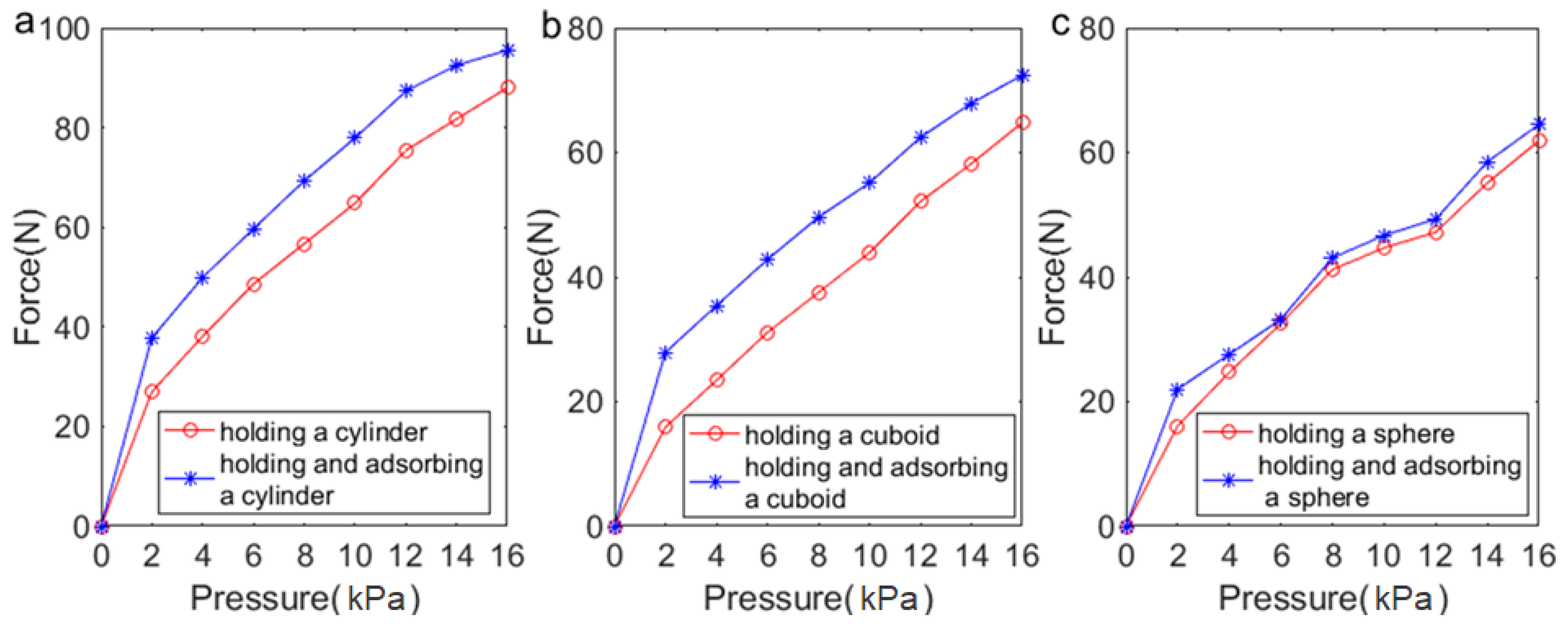
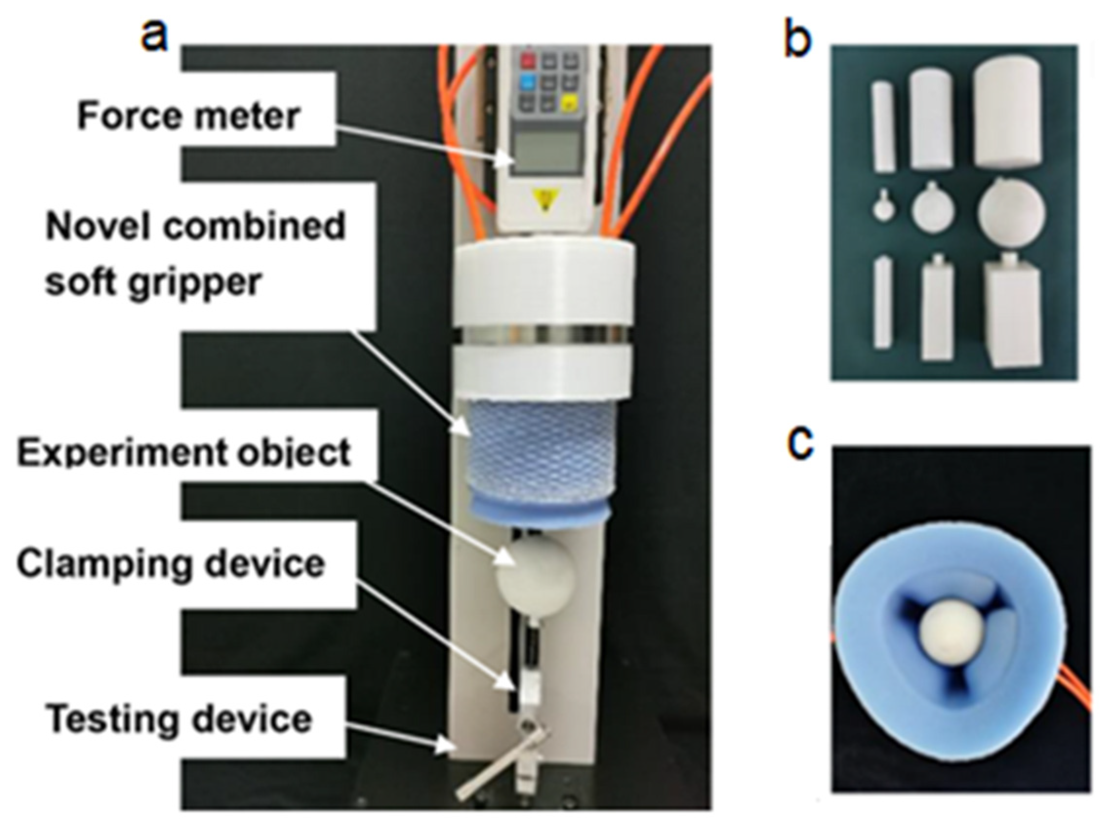
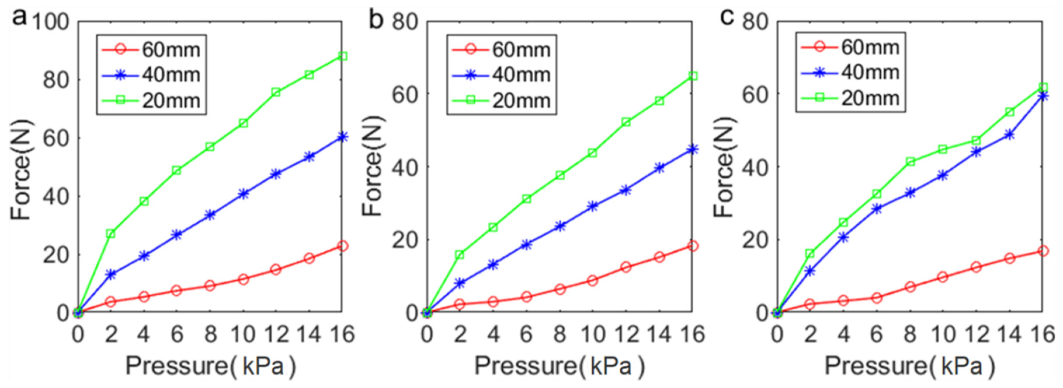
3.2. Load Capacity of the Cylindrical Soft Actuator
Experiments were conducted to evaluate the load capacity of the cylindrical soft actuator. The pneumatic novel combined soft gripper was mounted on the force meter that was fixed to the sliding block of the testing device (Figure 7a), and the cylindrical soft actuator was connected to the air chambers and the pressure regulating valve via air tubes. Experiment objects were 3D printed with PLA materials (Figure 7b), including three cylinders (diameter: 20, 40, and 60 mm), three spheres (diameter: 20, 40, and 60 mm), and three cuboids (diameter: 20, 40, and 60 mm). Under input air pressure (varied from 0 to 16 kPa at 2 kPa intervals), the cylindrical soft actuator grasped an experimental object fixed to the clamping device of the testing device (Figure 7c), and the sliding block pulled the force meter upward at a fixed velocity (0.5 mm/s) until the experimental object was released by the cylindrical soft actuator. Each experiment was repeated five times, and the results were averaged.
Figure 7.
(a) Load capacity testing device. (b) Experimental objects for grasping and holding experiment. (c) The state of grasping an experimental object using the cylindrical soft actuator.
The holding force is expressed by the maximum pulling force. The relationship between the maximum pulling forces and input air pressures is shown in Figure 8. As can be seen, the maximum pulling forces are 87.96, 64.84, and 61.90 N for grasping and holding cylinders, cuboids, and spheres, respectively, at 16 kPa air pressure. The maximum pulling force increased along with the growth of input air pressure. The maximum pulling force increases with the increase of the diameter of the experimental object at the same input air pressure. The most likely reason is that the contact area between three air chambers and the object increased with the increase of the diameter of the object. The holding force is proportional to the contact area. Therefore, the experimental results are consistent with the description of the theoretical model.
Figure 8.
The relationship between maximum pulling forces and input air pressures. (a) The maximum pulling force for grasping cylinders with different diameters. (b) The maximum pulling force for grasping cuboids with different diameters. (c) The maximum pulling force for grasping spheres with different diameters.
3.3. Adsorption Range of the Cylindrical Soft Actuator
To evaluate the adsorption range of the cylindrical soft actuator, we chose four curved surfaces with different curvature k (k = 1/35, 1/36, 1/40, and 1/65 mm−1) and four flat surfaces with different radii r (r = 35, 36, 40, and 65 mm) as experimental objects (Figure 9a). All the surfaces were fabricated through 3D printing with PLA material, and the mass of each experimental object was set as the same value, 100 g. The cylindrical soft actuator adsorbed the experimental objects at −15 kPa vacuum pressure (Figure 9b). Each experiment was repeated five times. Experimental results showed that the cylindrical soft actuator can 100% successfully adsorb curved surfaces with L > R, H > H1 and flat surfaces with R1 > L > R, H > H1 (L is the distance between the center line of the cylindrical soft actuator and the contact point of the surface and the cylindrical soft actuator. R is the inner diameter of the cylindrical soft actuator, R = 35 mm. H is the distance from the bottom end of the surface to the contact point of the cylindrical soft actuator and the surface. H1 is the distance between the open end of the cylindrical soft actuator and the contact point of the cylindrical soft actuator and the surface. R1 is the radius of the cylindrical soft actuator adsorption port, R1 = 55 mm) as shown in Figure 9(c-1,c-2). Furthermore, the cylindrical soft actuator can 100% successfully adsorb flat surfaces with R2 > R1 (R2 is the radius of the flat surface), as shown in Figure 9(c-3).
Figure 9.
(a) Experimental objects for adsorption experiment of the cylindrical soft actuator. (b) The state of adsorbing an experimental object using the cylindrical soft actuator. (c-1) Cylindrical soft actuator adsorbs a curved surface. (c-2,c-3) Cylindrical soft actuator adsorbs flat surfaces.
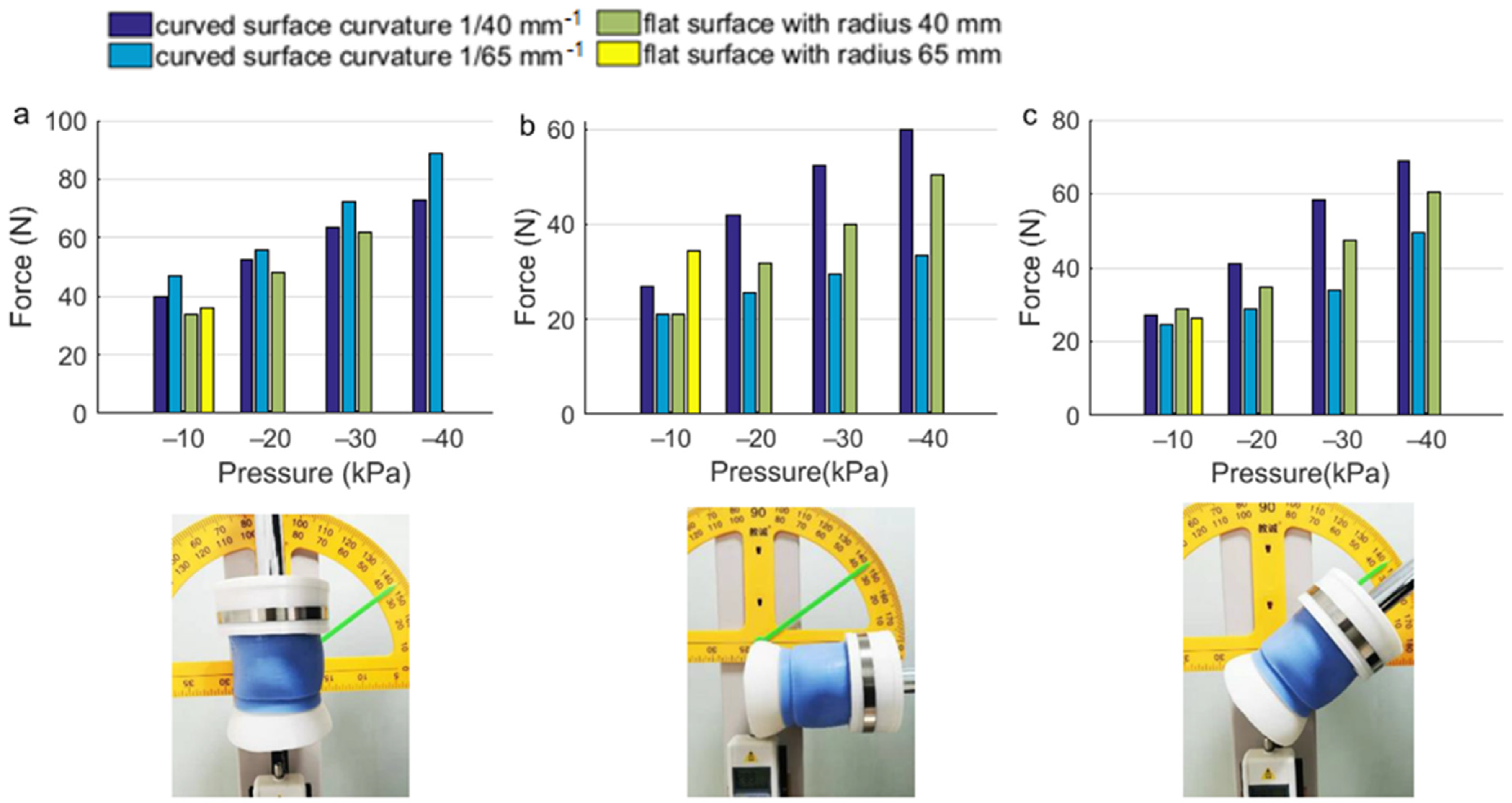
3.4. Adsorption Capacity of the Cylindrical Soft Actuator
We chose two curved surfaces with curvature k (k = 1/40 mm−1, 1/65 mm−1) and two flat surfaces with radius r (r = 40 mm, 65 mm) as experimental objects. The cylindrical soft actuator adsorbed an experiment object at a vacuum pressure that varied from 0 to −40 kPa at 10 kPa intervals. The cylindrical soft actuator was fixed on the upper part of the testing device, an experimental object was fixed to the force meter that pulled downward at a fixed velocity (0.5 mm/s) until the experimental object was released by the cylindrical soft actuator. Each experiment was repeated five times, and the results were averaged as shown in Figure 10. Experimental results show that the adsorption force increased along with the growth of vacuum pressure. The adsorption capacity of the cylindrical soft actuator in vertical orientation was greater than that in other orientations. With the same adsorption force, the cylindrical soft actuator buckled more easily in the horizontal orientation than in other orientations. Additionally, the cylindrical soft actuator was more suitable for adsorbing curved surfaces. The main reason is that when the cylindrical soft actuator is adsorbing a flat surface, radial shrinkage deformation of the cylindrical soft actuator increases with the increase of the negative pressure, and the excessive deformation means the cylindrical soft actuator and the flat surface cannot form a closed adsorption chamber.
Figure 10.
Adsorption forces of the cylindrical soft actuator. (a) The cylindrical soft actuator adsorbs objects in the vertical orientation. (b) The cylindrical soft actuator adsorbs objects in the horizontal orientation. (c) The cylindrical soft actuator adsorbs objects in the inclined orientation.
3.5. Adsorption Range of the Detachable Sucker
To determine the adsorption range of the detachable sucker, five curved surfaces with different curvature k (k = 1/3, 1/5, 1/10, 1/20, and 1/30 mm−1) and five flat surfaces with different radii r (r = 3, 5, 10, 20, and 30 mm) were chosen as experimental objects. These experimental objects were fabricated through 3D printing with PLA materials (Figure 11a). The mass of each experimental object was set as the same value, 100 g. The detachable sucker adsorbed the experimental object at a vacuum pressure of −15 kPa (Figure 11b). Each experiment was repeated five times. The picking up success rate of the detachable sucker is shown in Figure 11c. It is apparent that the success rate reaches 100% when the surface radius is equal to or exceeds 10 mm.
Figure 11.
(a) Experimental objects for adsorption experiment of the detachable sucker. (b) The state of adsorbing an experimental object using the detachable sucker. (c) The success rate of picking up experimental objects using the detachable sucker.
3.6. Adsorption Capacity of the Detachable Sucker
Several groups of experiments were conducted for evaluating the adsorption capacity of the detachable sucker. The experimental objects were a cylinder (diameter: 60 mm), sphere (diameter: 60 mm), and cuboid (diameter: 60 mm), as shown in Figure 7b. The testing device and the installation method of the experimental object are shown in Figure 7a. The cylindrical soft actuator and the detachable sucker acted on an experimental object simultaneously (Figure 3b). The novel combined soft gripper was pulled upward by the sliding block at a velocity of 0.5 mm/s until separating from the experimental object. Each experiment was repeated five times, and the results were averaged, as shown in Figure 12. The red curves revealed the maximum pulling force of the cylindrical soft actuator holding an experimental object under different input air pressures. The blue curves revealed the maximum pulling force of the cylindrical soft actuator and the detachable sucker acting on an experimental object simultaneously under different input air pressures and −50 kPa vacuum pressure. Input air pressure varied from 0 to 16 kPa at 2 kPa intervals. Compared with only using a cylindrical soft actuator to grasp objects, the use of the detachable sucker improves the load capacity (average load force increased 11.4, 10.2, and 2.7 N for picking up the cylinder, cuboid, and sphere, respectively).
Figure 12.
The red curves denote the maximum pulling forces of the cylindrical soft actuator that grasped experimental objects. The blue curves denote the maximum pulling forces of the cylindrical soft actuator and the detachable sucker acted on experimental objects, simultaneously. (a) A cylinder with diameter 60 mm. (b) A cuboid with diameter 60 mm. (c) A sphere with diameter 60 mm.
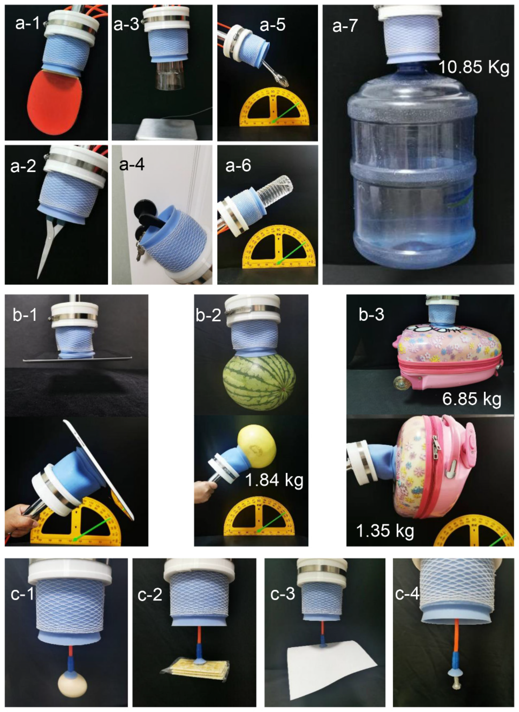
3.7. Application of the Novel Combined Soft Gripper
To prove that the novel combined soft gripper has high load capacity and large grasping range in practical application, we carried out several application experiments. As shown in Figure 13a and Supplementary Video S1, the cylindrical soft actuator cannot only grasp and hold a ping pong bat Figure 13(a-1), a pair of scissors Figure 13(a-2), and a glass cup Figure 13(a-3), but can also open a door Figure 13(a-4), pick up a spanner Figure 13(a-5), lift a bottle of water Figure 13(a-6), and lift a pail of water weighing up to 10.85 kg Figure 13(a-7). In addition, as illustrated in Figure 13b and Supplementary Video S2, utilizing the adsorption function, the cylindrical soft actuator can lift an iPad Figure 13(b-1), a watermelon and a grapefruit Figure 13(b-2), and a drawbar box weighing 6.85 kg Figure 13(b-3). In addition, as depicted in Figure 13c and Supplementary Video S3, the detachable sucker can pick up an egg Figure 13(c-1), a packet of biscuits Figure 13(c-2), and other objects that cannot be grasped by the cylindrical soft actuator, such as a piece of paper Figure 13(c-3), and a M6 bolt Figure 13(c-4). Furthermore, Supplementary Video S4 was added in this article to prove the applicability of the novel combined soft gripper under real-life dynamic scenarios. Application experiments showed that the novel combined soft gripper has a high load capacity and a large grasping range.
Figure 13.
Application of the pneumatic novel combined soft gripper. (a-1) Picking up a ping pong bat. (a-2) Picking up a pair of scissors. (a-3) Grasping a glass cup. (a-4) Opening a door. (a-5) Picking up a spanner. (a-6) Lifting a bottle of water. (a-7) Lifting a pail of water weighing 10.85 kg. (b-1) Picking up an iPad by adsorption function. (b-2) A watermelon and a grapefruit were lifted by adsorbing. (b-3) Lifting a drawbar box weighing 6.85 kg. (c-1) Picking up an egg. (c-2) Picking up a packet of biscuits. (c-3) Picking up a piece of paper. (c-4) A M6 bolt was picked up by the detachable sucker.
Table 1 shows the maximum load capacity of the existing soft grippers and the novel combined soft robotic gripper proposed in this paper. By comparison, it is apparent that the load capacity of the novel combined soft robotic gripper is the highest at a low air pressure.
Table 1.
Comparison of the maximum load capacity of soft grippers.
The structure of the novel combined soft robotic gripper proposed in this article is similar to the existing ring-shaped soft robotic gripper. Compared with the existing gripper, the novel combined soft robotic gripper has a larger grasping range, as shown in Table 2; d is the diameter of the object that the soft gripper can grasp.
Table 2.
Comparison of the grasping range of soft grippers.
4. Discussion and Conclusions
In this article, inspired by sea lampreys, we designed a pneumatic novel combined soft gripper that can realize a high load capacity and a large grasping range. The novel combined soft gripper consists of a cylindrical soft actuator and a detachable sucker. The novel combined soft gripper was fabricated by means of the casting molding method. Three internal air chambers of the cylindrical soft actuator can be inflated, which enables it to grasp and hold objects. Under vacuum pressure, the cylindrical soft actuator and the detachable sucker both can adsorb and then lift objects. Based on finite element analysis, we predicted the grasping range of the cylindrical soft actuator. Experiments confirmed the validity of the finite element model. We analyzed the mechanism of holding force and adsorption force theoretically. Several groups of experiments were conducted to determine the adsorption range, holding force, and adsorption force. Application experiments were conducted to lift a variety of objects with different weights, material properties, and shapes, including a ping pong bat, a pail of water weighing 10.85 kg, an iPad, a drawbar box, an egg, a M6 bolt, and so on. Experimental results indicate that the novel combined soft gripper has high load capacity and large grasping range.
However, the load capacity of the cylindrical soft actuator in the non-vertical orientation is lower than that in the vertical orientation, because of the bending and deformation of the cylindrical soft actuator that manipulates heavy objects in the non-vertical orientation. In addition, radial shrinkage and deformation occur when the cylindrical soft actuator adsorbs objects, owing to negative pressure, which reduces the adsorption capacity of the cylindrical soft actuator. In addition, one end of the cylindrical soft actuator is closed which prevents the cylindrical soft actuator from locating along the object to the most suitable position for grasping, which reduces grasping performance. Therefore, future work will combine stiffening material with the cylindrical soft actuator to realize high load manipulating in random orientations. The structure of the cylindrical soft actuator will be optimized to improve grasping performance. Future work will also establish a theoretical model of grasping force and analyze the factors that affect grasping force.
Supplementary Materials
The following are available online at https://www.mdpi.com/article/10.3390/act11010003/s1, Supplementary Video S1, Supplementary Video S2, Supplementary Video S3, Supplementary Video S4.
Author Contributions
Conceptualization, D.W., X.W. and J.Z.; method-ology, D.W.; software, D.W.; validation, D.W.; writing—original draft preparation, D.W.; resources, D.W.; writing—review and editing, X.W., J.Z. and Y.D.; supervision, X.W. All authors have read and agreed to the published version of the manuscript.
Funding
This research was funded by Key Research and Development Projects in Shaanxi Province, grant number 2021GY-265.
Institutional Review Board Statement
Not applicable.
Informed Consent Statement
Not applicable.
Data Availability Statement
Data is contained within the article as figures and tables.
Conflicts of Interest
The authors declare no conflict of interest.
References
- Rus, D.; Tolley, M.T. Design, fabrication and control of soft robots. Nature 2015, 521, 467–475. [Google Scholar] [CrossRef] [Green Version]
- Laschi, C.; Mazzolai, B.; Cianchetti, M. Soft robotics: Technologies and systems pushing the boundaries of robot abilities. Sci. Robot. 2016, 1, eaah3690. [Google Scholar] [CrossRef] [PubMed] [Green Version]
- Majidi, C. Soft robotics: A perspective-current trends and prospects for the future. Soft Robot. 2014, 1, 5–11. [Google Scholar] [CrossRef]
- Wang, L.; Iida, F. Deformation in Soft-Matter Robotics: A Categorization and Quantitative Characterization. IEEE Robot. Autom. Mag. 2015, 22, 125–139. [Google Scholar] [CrossRef]
- Hughes, J.; Culha, U.; Giardina, F.; Guenther, F.; Rosendo, A.; Iida, F. Soft manipulators and grippers: A review. Front. Robot. AI 2016, 3, 69. [Google Scholar] [CrossRef] [Green Version]
- Shintake, J.; Cacucciolo, V.; Floreano, D.; Shea, H. Soft Robotic Grippers. Adv. Mater. 2018, 30, 1707035. [Google Scholar] [CrossRef] [Green Version]
- Elango, N.; Faudzi, A.A.M. A review article: Investigations on soft materials for soft robot manipulations. Int. J. Adv. Manuf. Technol. 2015, 80, 1027–1037. [Google Scholar] [CrossRef] [Green Version]
- Martinez, R.V.; Branch, J.L.; Fish, C.R.; Jin, L.; Shepherd, R.F.; Nunes, R.M.; Whitesides, G.M. Robotic tentacles with three-dimensional mobility based on flexible elastomers. Adv. Mater. 2013, 25, 205–212. [Google Scholar] [CrossRef] [PubMed]
- Ranzani, T.; Gerboni, G.; Cianchetti, M.; Menciassi, A. A bioinspired soft manipulator for minimally invasive surgery. Bioinspir. Biomim. 2015, 10, 035008. [Google Scholar] [CrossRef]
- Li, H.; Yao, J.; Zhou, P.; Chen, X.; Xu, Y.; Zhao, Y. High-force soft pneumatic actuators based on novel casting method for robotic applications. Sens. Actuator A Phys. 2020, 306, 111957. [Google Scholar] [CrossRef]
- Wang, X.; Khara, A.; Chen, C. A soft pneumatic bistable reinforced actuator bioinspired by Venus Flytrap with enhanced grasping capability. Bioinspir. Biomim. 2020, 15, 056017. [Google Scholar] [CrossRef] [PubMed]
- Jeong, U.; In, H.K.; Cho, K.J. Implementation of various control algorithms for hand rehabilitation exercise using wearable robotic hand. Intell. Serv. Robot. 2013, 6, 181–189. [Google Scholar] [CrossRef]
- Lee, J.H.; Chung, Y.S.; Rodrigue, H. Long shape memory alloy tendon-based soft robotic actuators and implementation as a soft gripper. Sci. Rep. 2019, 9, 11251. [Google Scholar] [CrossRef]
- Modabberifar, M.; Spenko, M. A shape memory alloy-actuated gecko-inspired robotic gripper. Sens. Actuator A Phys. 2018, 276, 76–82. [Google Scholar] [CrossRef]
- Rodrigue, H.; Wang, W.; Kim, D.R.; Ahn, S.H. Curved Shape Memory Alloy-Based Soft Actuators and Application to Soft Gripper. Compos. Struct. 2017, 176, 398–406. [Google Scholar] [CrossRef]
- Shintake, J.; Rosset, S.; Schubert, B.; Floreano, D.; Shea, H. Versatile soft grippers with intrinsic electroadhesion based on multifunctional polymer actuators. Adv. Mater. 2016, 28, 231–238. [Google Scholar] [CrossRef] [PubMed]
- Shian, S.; Bertoldi, K.; Clarke, D.R. Dielectric Elastomer Based “grippers” for Soft Robotics. Adv. Mater. 2015, 27, 6814–6819. [Google Scholar] [CrossRef]
- Pourazadi, S.; Bui, H.; Menon, C. Investigation on a soft grasping gripper based on dielectric elastomer actuators. Smart Mater. Struct. 2019, 28, 035009. [Google Scholar] [CrossRef]
- Hao, Y.; Gong, Z.; Xie, Z.; Guan, S.; Yang, X.; Wang, T.; Wen, L. A Soft Bionic Gripper with Variable Effective Length. J. Bionic Eng. 2018, 15, 220–235. [Google Scholar] [CrossRef]
- Wang, Z.; Torigoe, Y.; Hirai, S. A prestressed soft gripper: Design, modeling, fabrication, and tests for food handling. IEEE Robot. Autom. Lett. 2017, 2, 1909–1916. [Google Scholar] [CrossRef]
- Suzumori, K.; Iikura, S.; Tanaka, H. Applying a flexible microactuator to robotic mechanisms. IEEE Control Syst. Mag. 1992, 12, 21–27. [Google Scholar]
- Terryn, S.; Roels, E.; Brancart, J.; Van Assche, G.; Vanderborght, B. Self-Healing and High Interfacial Strength in Multi-Material Soft Pneumatic Robots via Reversible Diels–Alder Bonds. Actuators 2020, 9, 34. [Google Scholar] [CrossRef]
- Wang, Z.; Or, K.; Hirai, S. A dual-mode soft gripper for food packaging. Robot. Auton. Syst. 2020, 125, 103427. [Google Scholar] [CrossRef]
- Deimel, R.; Brock, O. A compliant hand based on a novel pneumatic actuator. In Proceedings of the IEEE International Conference on Robotics and Automation, Karlsruhe, Germany, 6–10 May 2013; pp. 2047–2053. [Google Scholar]
- Deimel, R.; Brock, O. A novel type of compliant and underactuated robotic hand for dexterous grasping. Int. J. Robot. Res. 2016, 35, 161–185. [Google Scholar] [CrossRef] [Green Version]
- Zhou, J.; Chen, X.; Chang, U.; Lu, J.T.; Leung, C.C.Y.; Chen, Y.; Wang, Z. A soft-robotic approach to anthropomorphic robotic hand dexterity. IEEE Access 2019, 7, 101483–101495. [Google Scholar] [CrossRef]
- Deng, Z.; Li, M. Learning Optimal Fin-Ray Finger Design for Soft Grasping. Front. Robot. AI 2021, 7, 161. [Google Scholar] [CrossRef]
- Deimel, R.; Irmisch, P.; Wall, V.; Brock, O. Automated co-design of soft hand morphology and control strategy for grasping. In Proceedings of the 2017 IEEE/RSJ International Conference on Intelligent Robots and Systems (IROS) (Vancouver, BC), Vancouver, BC, Canada, 24–28 September 2017; pp. 1213–1218. [Google Scholar]
- Feng, N.; Wang, H.; Hu, F.; Gouda, M.A.; Gong, J.; Wang, F. A fiber-reinforced human-like soft robotic manipulator based on sEMG force estimation. Eng. Appl. Artif. Intell. 2019, 86, 56–67. [Google Scholar] [CrossRef]
- Wang, Y.; Xu, Q. Design and fabrication of a soft robotic manipulator driven by fiber-reinforced actuators. In Proceedings of the 2018 IEEE International Conference on Mechatronics, Robotics and Automation (ICMRA), Hefei, China, 18–21 May 2018; pp. 157–161. [Google Scholar]
- Li, Y.; Chen, Y.; Yang, Y.; Wei, Y. Passive particle jamming and its stiffening of soft robotic grippers. IEEE Trans. Robot. 2017, 33, 446–455. [Google Scholar] [CrossRef]
- Jiang, P.; Yang, Y.; Chen, M.Z.; Chen, Y. A variable stiffness gripper based on differential drive particle jamming. Bioinspir. Biomim. 2019, 14, 036009. [Google Scholar] [CrossRef] [PubMed]
- Jiang, Y.; Chen, D.; Liu, C.; Li, J. Chain-Like granular jamming: A novel stiffness-programmable mechanism for soft robotics. Soft Robot. 2019, 6, 118–132. [Google Scholar] [CrossRef]
- Hu, W.; Alici, G. Bioinspired three-dimensional-printed helical soft pneumatic actuators and their characterization. Soft Robot. 2020, 7, 267–282. [Google Scholar] [CrossRef]
- Yap, H.K.; Ng, H.Y.; Yeow, C.H. High-force soft printable pneumatics for soft robotic applications. Soft Robot. 2016, 3, 144–158. [Google Scholar] [CrossRef]
- Brown, E.; Rodenberg, N.; Amend, J.; Mozeika, A.; Steltz, E.; Zakin, M.R.; Jaeger, H.M. Universal robotic gripper based on the jamming of granular material. Proc. Natl. Acad. Sci. USA 2010, 107, 18809–18814. [Google Scholar] [CrossRef] [Green Version]
- Amend, J.R.; Brown, E.; Rodenberg, N.; Jaeger, H.M.; Lipson, H. A positive pressure universal gripper based on the jamming of granular material. IEEE Trans. Robot. 2012, 28, 341–350. [Google Scholar] [CrossRef]
- Amend, J.; Cheng, N.; Fakhouri, S.; Culley, B. Soft robotics commercialization: Jamming grippers from research to product. Soft Robot. 2016, 3, 213–222. [Google Scholar] [CrossRef]
- Wang, Z.; Kanegae, R.; Hirai, S. Circular shell gripper for handling food products. Soft Robot. 2021, 8, 542–554. [Google Scholar] [CrossRef] [PubMed]
- Dang, Y.; Stommel, M.; Cheng, L.K.; Xu, W. A soft ring-shaped actuator for radial contracting deformation: Design and modeling. Soft Robot. 2019, 6, 444–454. [Google Scholar] [CrossRef]
- Li, H.; Yao, J.; Zhou, P.; Chen, X.; Xu, Y.; Zhao, Y. High-Load soft grippers based on bionic winding effect. Soft Robot. 2019, 6, 276–288. [Google Scholar] [CrossRef] [PubMed]
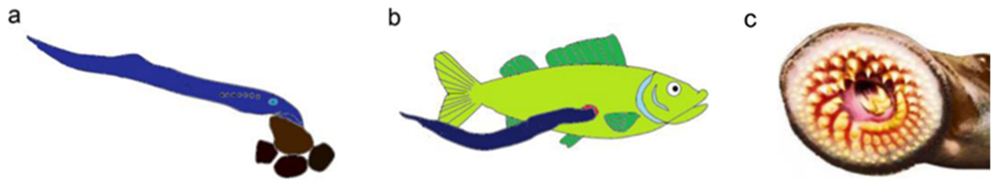
- Osório, J.; Rétaux, S. The lamprey in evolutionary studies. Dev. Genes Evol. 2008, 218, 221–235. [Google Scholar] [CrossRef]
- Applegate, V.C. The sea lamprey in the Great Lakes. Sci. Mon. 1951, 72, 275–281. [Google Scholar]
Publisher’s Note: MDPI stays neutral with regard to jurisdictional claims in published maps and institutional affiliations. |
© 2021 by the authors. Licensee MDPI, Basel, Switzerland. This article is an open access article distributed under the terms and conditions of the Creative Commons Attribution (CC BY) license (https://creativecommons.org/licenses/by/4.0/).


