Ultimate Shear of RC Beams with Corroded Stirrups and Strengthened with FRP


Abstract
1. Introduction
2. Effective Strain of FRP at ULS
2.1. Rupture of FRP
2.2. Debonding of FRP
3. Empirical Relationship for the Yield Strength of Corrosion-Damaged Steel Stirrups
4. Analytical Model for the Ultimate Shear of Corrosion-Damaged Steel Stirrups Strengthened with FRP
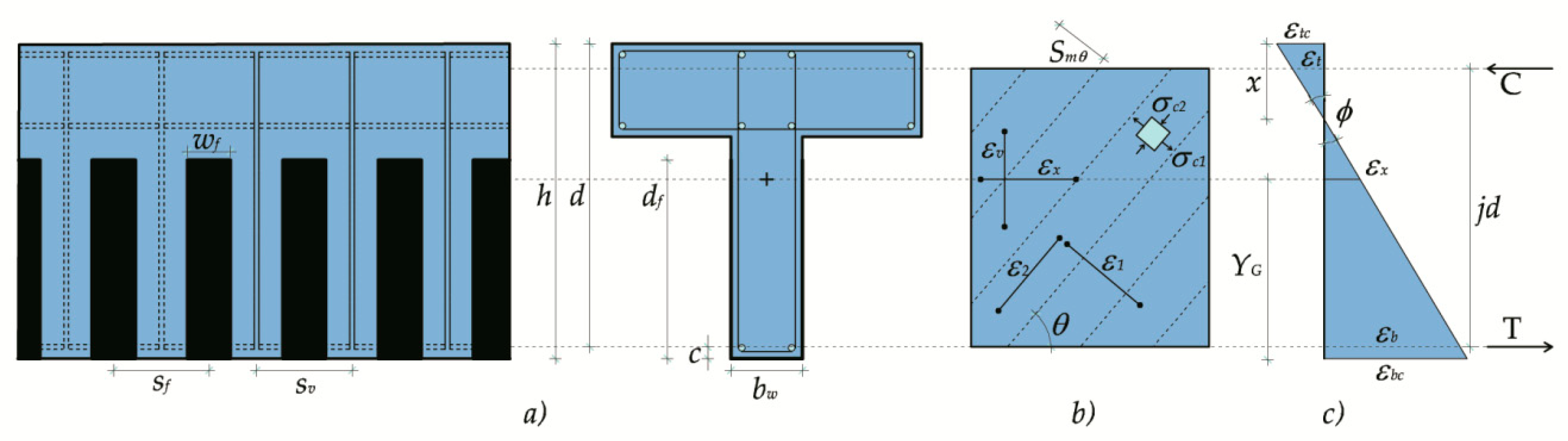
4.1. Shear Model
4.1.1. Equilibrium Equations
4.1.2. Compatibility Conditions
4.1.3. Constitutive Laws
4.2. Flexural Model
5. Iterative Procedure
6. Validation of the Proposed Formulation and Discussion
6.1. RC Beams with Un-Corroded Stirrups and FRP Reinforcement
6.2. RC Beams with Corroded Stirrups and FRP Reinforcement
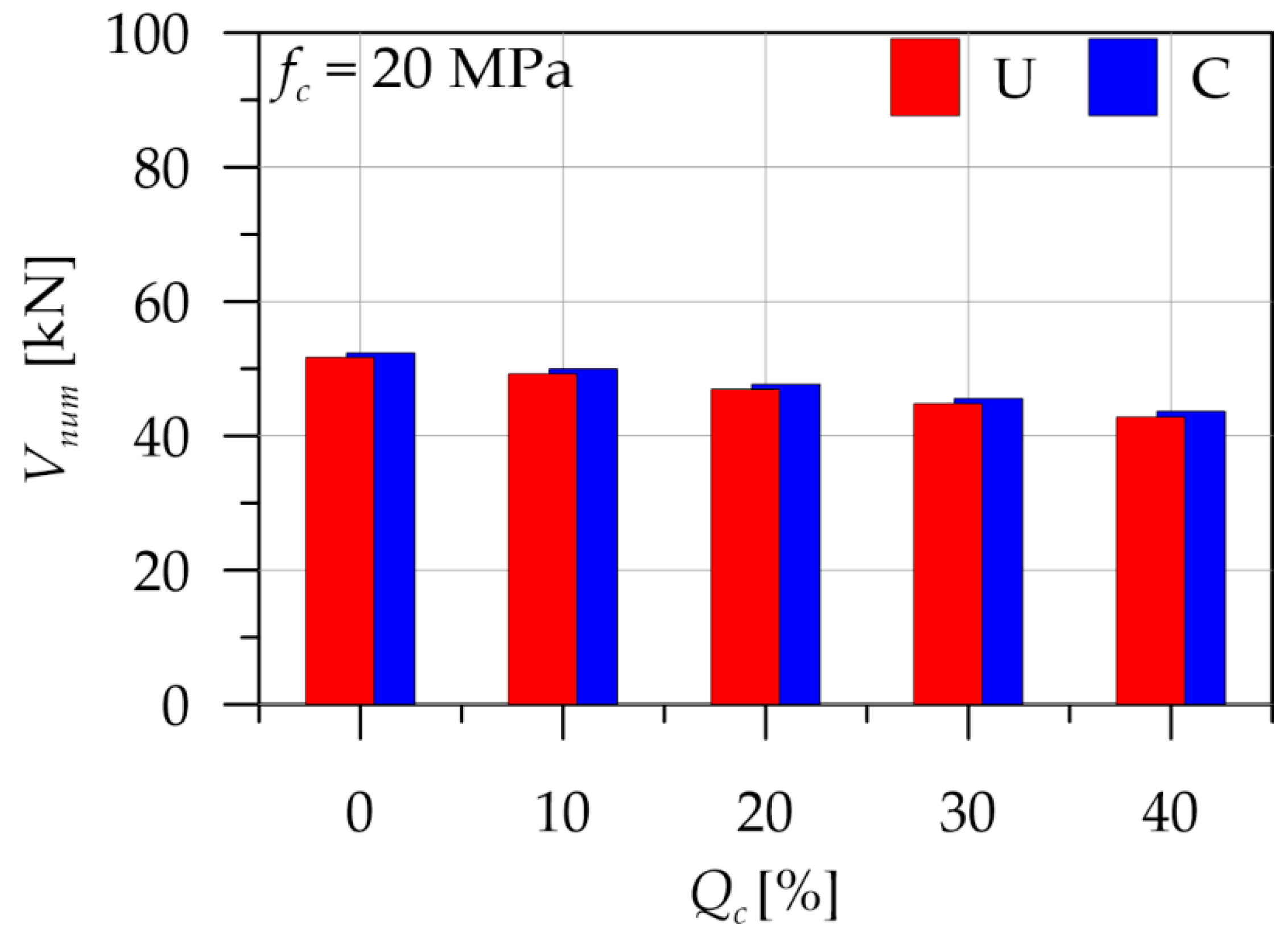
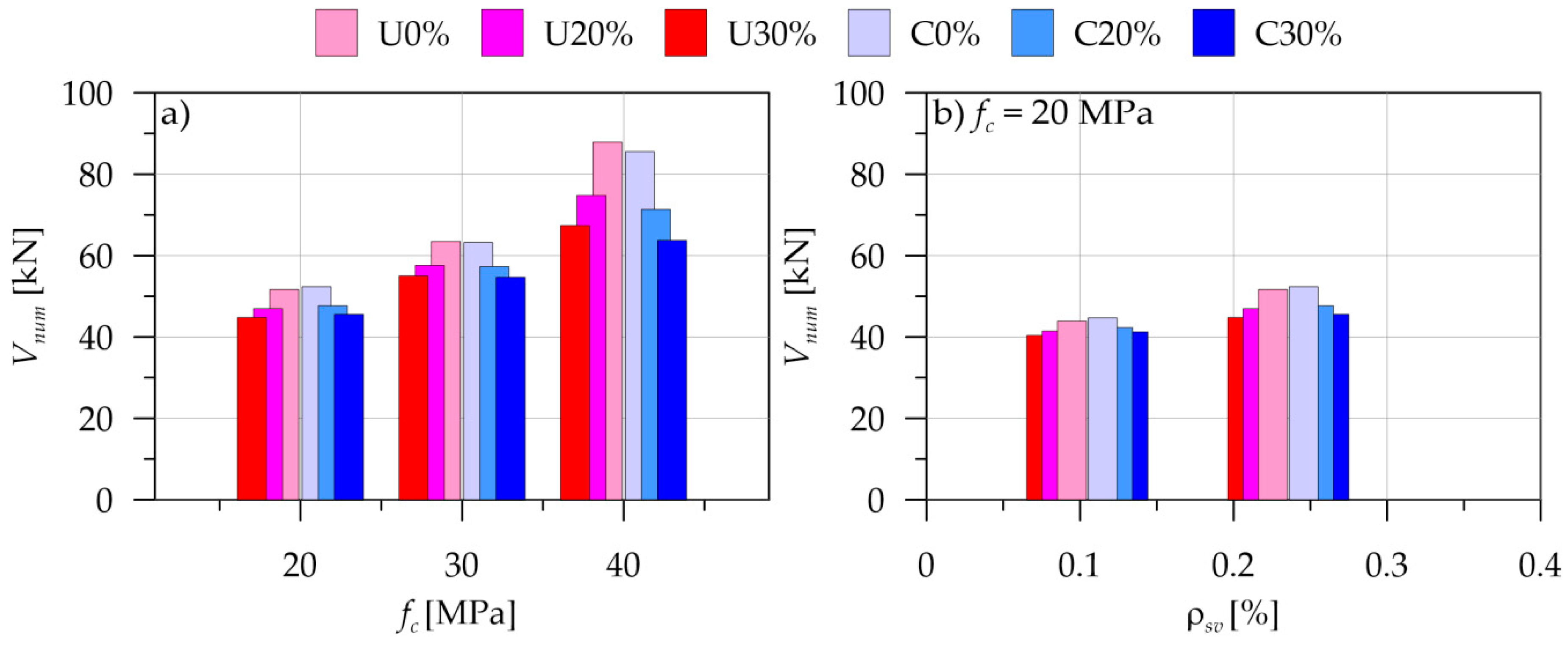
7. Parametric Analysis
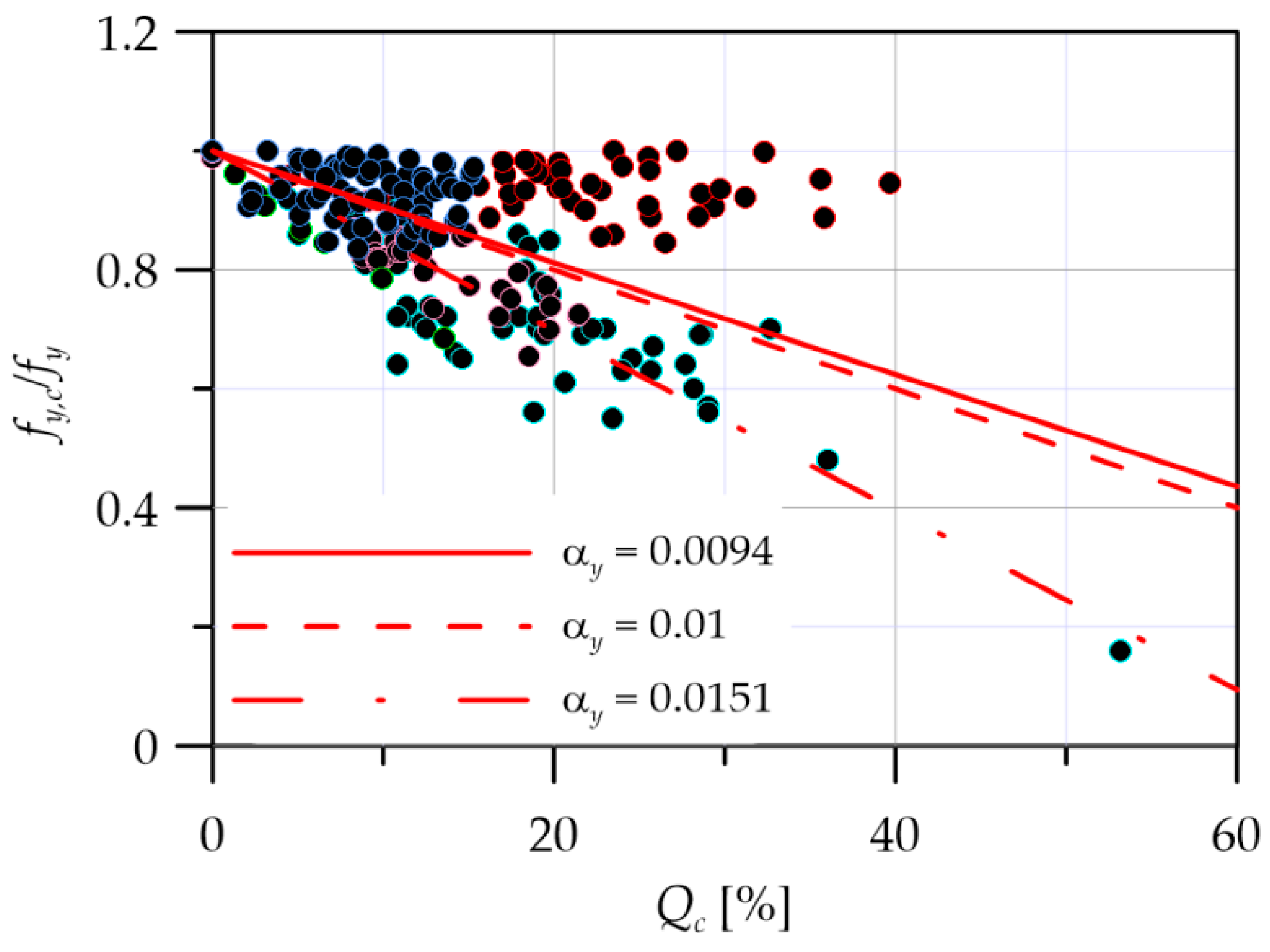
7.1. Effect of Degree of Corrosion
7.2. Effect of Concrete Cylinder Compressive Strength and Geometrical Stirrup Ratio
8. Conclusions
Author Contributions
Funding
Conflicts of Interest
Nomenclature
| AAE | Average Absolute Error |
| AE | Absolute error |
| Af | Area of the FRP reinforcement |
| Asv, Asv,c | Area of non corroded and corroded stirrup |
| a | Shear span |
| bw, h, d | Width, height and effective depth of the cross-section |
| c | Concrete cover |
| C, T | Resultant forces in the concrete and the steel rebar related to the i-th layer |
| df | Depth of FRP reinforcement |
| dg | Maximum coarse aggregate size (in mm) |
| Ec, Ef, Es | Young modulus of concrete, FRP and steel |
| fc, fct | Peak compressive stress of concrete and tensile strength of concrete |
| fyl | Yield strength of longitudinal steel rebar |
| fyv, fyv,c | Yield strength of non corroded and corroded steel stirrup |
| jd | Inner lever arm |
| N, M, V | Axial force, bending moment and shear force |
| Rfr, Rfd | Rupture and debonding effectiveness factors |
| sv | Stirrups spacing |
| sf, tf, wf | Spacing, thickness, and width of FRP sheets |
| Sm, Sml, Smv | Average crack spacing |
| w | Shear crack width |
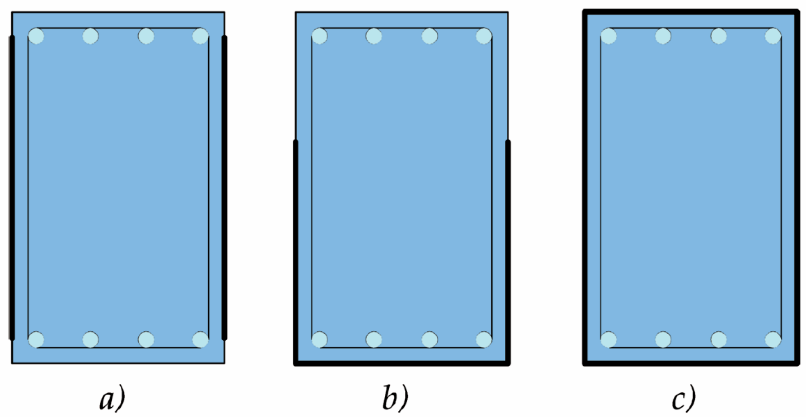
| W | Wrap arrangement (S, U, or C) |
| x | Neutral axis depth |
| ε1, ε2 | Principal strains |
| εb, εt | Bottom and top longitudinal force strain |
| εcb, εct | Bottom and top longitudinal concrete strain |
| εc0 | Concrete strain at the peak compressive stress |
| εfe, εfu | Effective and nominal ultimate strain of FRP |
| εx | Axial strain at centroid level |
| εv | Average vertical strain |
| ƞ | Compression softening factor |
| ɵ | Crack angle |
| ρfv, ρsv,c | Geometrical ratio of FRP and corroded stirrup reinforcement |
| ρsb, ρst | Geometrical ratio of bottom and top longitudinal rebar |
| ϕ | Curvature |
| σc1, σc2 | Principal stresses |
| σc1max | Maximum principal tensile stress |
| σcv | Clamping stresses |
| σfv, σsv,c, σsl | Stress of FRP, corroded stirrups and longitudinal rebars |
| τ, τi | Shear stress and local shear stress on the crack surface |
References
- Colajanni, P.; Recupero, A.; Ricciardi, G.; Spinella, N. Failure by corrosion in PC bridges: A case history of a viaduct in Italy. Int. J. Struct. Integr. 2016, 7, 181–193. [Google Scholar] [CrossRef]
- Presti, A.L.; Recupero, A.; Spinella, N. Influence of rebar corrosion on RC frame push-over response. In Proceedings of the High Tech Concrete: Where Technology and Engineering Meet—2017 Fib Symposium, Maastricht, The Netherlands, 12–14 June 2017; pp. 2118–2126. [Google Scholar]
- Cesetti, A.; Mancini, G.; Tondolo, F.; Recupero, A.; Spinella, N. Physical model for structural evaluation of R.C. beams in presence of corrosion. In Proceedings of the 4th International Conference on Concrete Repair, Rehabilitation and Retrofitting (ICCRRR 2015), Leipzig, Germany, 5–7 October 2016; pp. 107–114. [Google Scholar]
- Rodriguez, J.; Ortega, L.M.; Casal, J.; Diez, J.M. Assessing structural conditions of concrete structures with corroded reinforcement. In Proceedings of the Conference, Concrete Repair, Rehabilitation and Protection, Dundee, UK, 24–26 June 1996; E & FN Spon: Dundee, UK, 1996; pp. 65–78. [Google Scholar]
- Bossio, A.; Fabbrocino, F.; Monetta, T.; Lignola, G.P.; Prota, A.; Manfredi, G.; Bellucci, F. Corrosion effects on seismic capacity of reinforced concrete structures. Corros. Rev. 2018. [Google Scholar] [CrossRef]
- El-Maaddawy, T.; Chekfeh, Y. Shear Strengthening of T-Beams with Corroded Stirrups Using Composites. ACI Struct. J. 2013, 110, 779–790. [Google Scholar]
- Qin, S.; Dirar, S.; Yang, J.; Chan, A.H.C.; Elshafie, M. CFRP Shear Strengthening of Reinforced-Concrete T-Beams with Corroded Shear Links. J. Compos. Constr. 2015, 19, 04014081. [Google Scholar] [CrossRef]
- Li, H.; Wu, J.; Wang, Z. Shear Performance of Reinforced Concrete Beams with Corroded Stirrups Strengthened with Carbon Fiber-Reinforced Polymer. ACI Struct. J. 2016, 113, 51–61. [Google Scholar] [CrossRef]
- Mosallam, A.S.; Banerjee, S. Shear enhancement of reinforced concrete beams strengthened with FRP composite laminates. Compos. Part B Eng. 2007, 38, 781–793. [Google Scholar] [CrossRef]
- Val, D.V. Deterioration of Strength of RC Beams due to Corrosion and Its Influence on Beam Reliability. J. Struct. Eng. 2007, 133, 1297–1306. [Google Scholar] [CrossRef]
- Recupero, A.; Spinella, N.; Tondolo, F. A model for the analysis of ultimate capacity of RC and PC corroded beams. Adv. Civ. Eng. 2018. [Google Scholar] [CrossRef]
- Recupero, A.; Spinella, N.; Tondolo, F. Failure analysis of corroded RC beams subjected to shear-flexural actions. Eng. Fail. Anal. 2018. [Google Scholar] [CrossRef]
- Zhang, W.; Ye, Z.; Gu, X. Effects of stirrup corrosion on shear behaviour of reinforced concrete beams. Struct. Infrastruct. Eng. 2017, 13, 1081–1092. [Google Scholar] [CrossRef]
- Campione, G.; Cannella, F. Engineering failure analysis of corroded R.C. beams in flexure and shear. Eng. Fail. Anal. 2018, 86, 100–114. [Google Scholar] [CrossRef]
- Colajanni, P.; La Mendola, L.; Recupero, A.; Spinella, N. Stress field model for strengthening of shear-flexure critical RC beams. J. Compos. Constr. 2017, 21. [Google Scholar] [CrossRef]
- Marí, A.; Cladera, A.; Oller, E.; Bairán, J. Shear design of FRP reinforced concrete beams without transverse reinforcement. Compos. Part B Eng. 2014, 57, 228–241. [Google Scholar] [CrossRef]
- Triantafyllou, G.G.; Rousakis, T.C.; Karabinis, A.I. Analytical assessment of the bearing capacity of RC beams with corroded steel bars beyond concrete cover cracking. Compos. Part B Eng. 2017, 119, 132–140. [Google Scholar] [CrossRef]
- Alabdulhady, M.Y.; Aljabery, K.; Sneed, L.H. Analytical Study on the Torsional Behavior of Reinforced Concrete Beams Strengthened with FRCM Composite. J. Compos. Constr. 2019, 23, 04019006. [Google Scholar] [CrossRef]
- Elghazy, M.; El Refai, A.; Ebead, U.; Nanni, A. Experimental results and modelling of corrosion-damaged concrete beams strengthened with externally-bonded composites. Eng. Struct. 2018, 172, 172–186. [Google Scholar] [CrossRef]
- Vecchio, F.J.; Collins, M.P. The Modified Compression-Field Theory for Reinforced Concrete Elements Subjected to Shear. ACI J. Proc. 1986, 83, 219–231. [Google Scholar]
- Chen, J.F.; Teng, J.G. Shear capacity of FRP-strengthened RC beams: FRP debonding. Constr. Build. Mater. 2003, 17, 27–41. [Google Scholar] [CrossRef]
- Chen, J.F.; Teng, J.G. Shear Capacity of Fiber-Reinforced Polymer-Strengthened Reinforced Concrete Beams: Fiber Reinforced Polymer Rupture. J. Struct. Eng. 2003, 129, 615–625. [Google Scholar] [CrossRef]
- Cairns, J.; Plizzari, G.A.; Du, Y.; Law, D.W.; Franzoni, C. Mechanical Properties of Corrosion-Damaged Reinforcement. ACI Mater. J. 2005, 102, 256–264. [Google Scholar]
- Cobo, A.; Moreno, E.; Cánovas, M.F.; Cánovas, M.F. Mechanical properties variation of B500SD high ductility reinforcement regarding its corrosion degree. Mater. Construcción 2011, 61, 517–532. [Google Scholar]
- Zhang, W.; Song, X.; Gu, X.; Li, S. Tensile and fatigue behavior of corroded rebars. Constr. Build. Mater. 2012, 34, 409–417. [Google Scholar] [CrossRef]
- Apostolopoulos, C.A.; Demis, S.; Papadakis, V.G. Chloride-induced corrosion of steel reinforcement – Mechanical performance and pit depth analysis. Constr. Build. Mater. 2013, 38, 139–146. [Google Scholar] [CrossRef]
- Fernandez, I.; Bairán, J.M.; Marí, A.R. Mechanical model to evaluate steel reinforcement corrosion effects on σ–ε and fatigue curves. Experimental calibration and validation. Eng. Struct. 2016, 118, 320–333. [Google Scholar] [CrossRef]
- Imperatore, S.; Rinaldi, Z.; Drago, C. Degradation relationships for the mechanical properties of corroded steel rebars. Constr. Build. Mater. 2017, 148, 219–230. [Google Scholar] [CrossRef]
- Zhu, W.; François, R.; Cleland, D.; Coronelli, D. Failure mode transitions of corroded deep beams exposed to marine environment for long period. Eng. Struct. 2015, 96, 66–77. [Google Scholar] [CrossRef]
- Biondini, F.; Vergani, M. Deteriorating beam finite element for nonlinear analysis of concrete structures under corrosion. Struct. Infrastruct. Eng. 2015, 11, 519–532. [Google Scholar] [CrossRef]
- Colalillo, M.A.; Sheikh, S.A. Behavior of Shear-Critical Reinforced Concrete Beams Strengthened with Fiber-Reinforced Polymer—Analytical Method. ACI Struct. J. 2014, 111, 1385–1396. [Google Scholar] [CrossRef]
- Mostafaei, H.; Vecchio, F.J. Uniaxial Shear-Flexure Model for Reinforced Concrete Elements. J. Struct. Eng. 2008, 134, 1538–1547. [Google Scholar] [CrossRef]
- Colajanni, P.; La Mendola, L.; Mancini, G.; Recupero, A.; Spinella, N. Shear capacity in concrete beams reinforced by stirrups with two different inclinations. Eng. Struct. 2014, 81, 444–453. [Google Scholar] [CrossRef]
- Baghi, H.; Barros, J.A.O.; Menkulasi, F. Shear strengthening of reinforced concrete beams with Hybrid Composite Plates (HCP) technique: Experimental research and analytical model. Eng. Struct. 2016, 125, 504–520. [Google Scholar] [CrossRef]
- Rousakis, T.C.; Saridaki, M.E.; Mavrothalassitou, S.A.; Hui, D. Utilization of hybrid approach towards advanced database of concrete beams strengthened in shear with FRPs. Compos. Part B Eng. 2016, 85, 315–335. [Google Scholar] [CrossRef]
- Yapa, H.D.; Lees, J.M. Rectangular Reinforced Concrete Beams Strengthened with CFRP Straps. J. Compos. Constr. 2014, 18, 04013032. [Google Scholar] [CrossRef]
- Sigrist, V. Generalized Stress Field Approach for Analysis of Beams in Shear. ACI Struct. J. 2011, 108, 479–487. [Google Scholar]
- CEN Eurocode 2—Design of Concrete Structures: Part 1–1. General Rules and Rules for Buildings. CEN (Comitee for Standardization) 1992-1-1. 2005.
- Italian MIT, D.M. Nuove Norme Tecniche Per le Costruzioni. Gazzetta Ufficiale, 14 January 2008; Volume 29. (In Italian) [Google Scholar]
- Bentz, E.C.; Vecchio, F.J.; Collins, M.P. Simplified Modified Compression Field Theory for Calculating Shear Strength of Reinforced Concrete Elements. ACI Struct. J. 2006, 103, 614–624. [Google Scholar]
- Colajanni, P.; Papia, M.; Spinella, N. Stress-strain law for confined concrete with hardening or softening behavior. Adv. Civ. Eng. 2013, 2013. [Google Scholar] [CrossRef]
- Spinella, N. N-M-χ interaction for arbitrary cross section under biaxial bending and axial load. Pollack Period. 2013, 8, 87–100. [Google Scholar] [CrossRef]
- Colalillo, M.A.; Sheikh, S.A. Behavior of Shear-Critical Reinforced Concrete Beams Strengthened with Fiber-Reinforced Polymer—Experimentation. ACI Struct. J. 2014, 111, 1373–1384. [Google Scholar] [CrossRef]
- Bousselham, A.; Chaallal, O. Behavior of Reinforced Concrete T-Beams Strengthened in Shear with Carbon Fiber-Reinforced Polymer— An Experimental Study. ACI Struct. J. 2006, 103, 339–347. [Google Scholar]


| Ref. | Spec. | bw | d | fc | fyv | ρsv | ffu | Ef | ρfv | W | Vexp | Vnum | Vexp/Vnum | AE | AAE |
|---|---|---|---|---|---|---|---|---|---|---|---|---|---|---|---|
| mm | mm | MPa | MPa | % | MPa | GPa | % | kN | kN | kN | |||||
| [43] 1 | S0-US | 400 | 545 | 53.3 | 501 | 0.00 | 961 | 95 | 0.25 | U | 377.0 | 395.2 | 0.95 | 18.2 | 0.05 |
| S0-UA | 400 | 545 | 53.3 | 501 | 0.00 | 961 | 95 | 0.50 | U | 534.0 | 493.6 | 1.08 | 40.4 | 0.08 | |
| S0-CS | 400 | 545 | 47.6 | 501 | 0.00 | 961 | 95 | 0.25 | C | 695.0 | 522.2 | 1.33 | 172.8 | 0.25 | |
| S0-CA | 400 | 545 | 53.3 | 501 | 0.00 | 961 | 95 | 0.50 | C | 915.0 | 1151.8 | 0.79 | 236.8 | 0.26 | |
| S5-US | 400 | 545 | 47.6 | 501 | 0.07 | 961 | 95 | 0.25 | U | 518.0 | 480.3 | 1.08 | 37.7 | 0.07 | |
| S5-UA | 400 | 545 | 47.5 | 501 | 0.07 | 961 | 95 | 0.50 | U | 622.0 | 563.7 | 1.10 | 58.3 | 0.09 | |
| S5-CS | 400 | 545 | 47.6 | 501 | 0.07 | 961 | 95 | 0.25 | C | 725.0 | 611.1 | 1.19 | 113.9 | 0.16 | |
| S2-US | 400 | 545 | 47.5 | 501 | 0.14 | 961 | 95 | 0.25 | U | 629.0 | 703.3 | 0.89 | 74.3 | 0.12 | |
| S2-UA | 400 | 545 | 47.5 | 501 | 0.14 | 961 | 95 | 0.50 | U | 688.0 | 776.3 | 0.89 | 88.3 | 0.13 | |
| S2-CS | 400 | 545 | 47.5 | 501 | 0.14 | 961 | 95 | 0.25 | C | 844.0 | 815.5 | 1.03 | 28.5 | 0.03 | |
| S2-CA | 400 | 545 | 47.5 | 501 | 0.14 | 961 | 95 | 0.50 | C | 866.0 | 1320.6 | 0.66 | 454.6 | 0.52 | |
| [44] 2 | S0-0.5L-400 | 152 | 350 | 25.0 | 645 | 0.00 | 3159 | 243 | 0.08 | U | 102.4 | 138.6 | 0.74 | 36.2 | 0.35 |
| S0-1L-400 | 152 | 350 | 25.0 | 645 | 0.00 | 3159 | 243 | 0.14 | U | 120.0 | 160.2 | 0.75 | 40.2 | 0.33 | |
| S0-2L-400 | 152 | 350 | 25.0 | 645 | 0.00 | 3159 | 243 | 0.28 | U | 122.0 | 189.7 | 0.64 | 67.7 | 0.56 | |
| S1-0.5L-400 | 152 | 350 | 25.0 | 645 | 0.38 | 3159 | 243 | 0.08 | U | 282.0 | 323.3 | 0.87 | 41.3 | 0.15 | |
| S1-2L-400 | 152 | 350 | 25.0 | 645 | 0.38 | 3159 | 243 | 0.28 | U | 267.2 | 333.2 | 0.80 | 66.0 | 0.25 | |
| S0-1L-220 | 95 | 175 | 26.0 | 420 | 0.00 | 3650 | 231 | 0.14 | U | 59.3 | 51.7 | 1.15 | 7.6 | 0.13 | |
| S0-2L-220 | 95 | 175 | 26.0 | 420 | 0.00 | 3650 | 231 | 0.28 | U | 68.5 | 57.7 | 1.19 | 10.8 | 0.16 | |
| S1-1L-220 | 95 | 175 | 26.0 | 420 | 0.38 | 3650 | 231 | 0.14 | U | 95.7 | 78.9 | 1.21 | 16.8 | 0.18 | |
| S1-2L-220 | 95 | 175 | 26.0 | 420 | 0.38 | 3650 | 231 | 0.28 | U | 105.1 | 83.0 | 1.27 | 22.1 | 0.21 | |
| Mean | 0.98 | 81.6 | 0.20 | ||||||||||||
| CoV | 0.21 | 1.28 | 0.71 |
| Ref. | Spec. | bw | d | fc | fyv | ρsv | Qc | ffu | Ef | ρfv | W | Vexp | Vnum | Vexp/Vnum | AE | AAE |
|---|---|---|---|---|---|---|---|---|---|---|---|---|---|---|---|---|
| mm | mm | MPa | MPa | % | % | MPa | GPa | % | kN | kN | kN | |||||
| [6] 1 | C1-NS | 300 | 200 | 32.0 | 344 | 0.33 | 8 | 98.4 | 85.1 | 1.16 | 13.3 | 0.13 | ||||
| C2-NS | 300 | 200 | 32.0 | 344 | 0.33 | 15 | 92.8 | 80.8 | 1.15 | 12.0 | 0.13 | |||||
| C1-EB1 | 300 | 200 | 32.0 | 344 | 0.33 | 8 | 894 | 65 | 0.37 | U | 120.0 | 120.1 | 1.00 | 0.1 | 0.00 | |
| C2-EB1 | 300 | 200 | 32.0 | 344 | 0.33 | 15 | 894 | 65 | 0.37 | U | 100.0 | 116.3 | 0.86 | 16.3 | 0.16 | |
| C2-EB2 | 300 | 200 | 32.0 | 344 | 0.33 | 15 | 894 | 65 | 0.74 | U | 107.2 | 125.5 | 0.85 | 18.3 | 0.17 | |
| C2-EB3 | 300 | 200 | 32.0 | 344 | 0.33 | 15 | 894 | 65 | 1.11 | U | 120.0 | 130.7 | 0.92 | 10.7 | 0.09 | |
| [7] 2 | N07 | 260 | 295 | 30.7 | 542 | 0.29 | 6 | 148.0 | 134.4 | 1.10 | 13.6 | 0.09 | ||||
| N12 | 260 | 295 | 30.7 | 542 | 0.29 | 12 | 155.0 | 126.7 | 1.22 | 28.3 | 0.18 | |||||
| S07 | 260 | 295 | 30.5 | 542 | 0.29 | 6 | 986 | 96 | 1.60 | U | 174.0 | 200.2 | 0.87 | 26.2 | 0.15 | |
| S12 | 260 | 295 | 30.5 | 542 | 0.29 | 12 | 986 | 96 | 1.60 | U | 174.0 | 198.7 | 0.88 | 24.7 | 0.14 | |
| [8] 3 | B1 | 120 | 165 | 24.6 | 440 | 0.24 | 1 | 61.2 | 48.3 | 1.27 | 12.9 | 0.21 | ||||
| B2 | 120 | 165 | 27.3 | 440 | 0.24 | 3 | 58.2 | 50.0 | 1.16 | 8.2 | 0.14 | |||||
| B3 | 120 | 165 | 29.1 | 440 | 0.24 | 4 | 45.0 | 50.8 | 0.89 | 5.8 | 0.13 | |||||
| B4 | 120 | 165 | 26.0 | 440 | 0.24 | 5 | 55.0 | 48.1 | 1.14 | 6.9 | 0.12 | |||||
| B5 | 120 | 165 | 29.8 | 440 | 0.24 | 7 | 42.5 | 50.4 | 0.84 | 7.9 | 0.19 | |||||
| B6 | 120 | 165 | 28.9 | 440 | 0.24 | 7 | 52.0 | 49.5 | 1.05 | 2.5 | 0.05 | |||||
| B7 | 120 | 165 | 25.6 | 440 | 0.24 | 10 | 40.0 | 46.1 | 0.87 | 6.1 | 0.15 | |||||
| SB1 | 120 | 165 | 24.6 | 440 | 0.24 | 1 | 3060 | 210 | 0.06 | U | 58.1 | 58.5 | 0.99 | 0.4 | 0.01 | |
| SB2 | 120 | 165 | 27.3 | 440 | 0.24 | 3 | 3060 | 210 | 0.06 | U | 65.0 | 61.2 | 1.06 | 3.8 | 0.06 | |
| SB3 | 120 | 165 | 29.1 | 440 | 0.24 | 4 | 3060 | 210 | 0.06 | U | 62.5 | 62.6 | 1.00 | 0.1 | 0.00 | |
| SB4 | 120 | 165 | 26.0 | 440 | 0.24 | 5 | 3060 | 210 | 0.06 | U | 61.1 | 59.1 | 1.03 | 2.0 | 0.03 | |
| SB5 | 120 | 165 | 29.8 | 440 | 0.24 | 7 | 3060 | 210 | 0.06 | U | 60.0 | 62.6 | 0.96 | 2.6 | 0.04 | |
| SB6 | 120 | 165 | 28.9 | 440 | 0.24 | 7 | 3060 | 210 | 0.06 | U | 64.0 | 61.5 | 1.04 | 2.5 | 0.04 | |
| SB7 | 120 | 165 | 25.6 | 440 | 0.24 | 10 | 3060 | 210 | 0.06 | U | 68.8 | 57.2 | 1.20 | 11.6 | 0.17 | |
| 1.02 | 9.86 | 0.11 | ||||||||||||||
| 0.13 | 0.84 | 0.59 |
© 2019 by the authors. Licensee MDPI, Basel, Switzerland. This article is an open access article distributed under the terms and conditions of the Creative Commons Attribution (CC BY) license (http://creativecommons.org/licenses/by/4.0/).
Share and Cite
Spinella, N.; Colajanni, P.; Recupero, A.; Tondolo, F. Ultimate Shear of RC Beams with Corroded Stirrups and Strengthened with FRP. Buildings 2019, 9, 34. https://doi.org/10.3390/buildings9020034
Spinella N, Colajanni P, Recupero A, Tondolo F. Ultimate Shear of RC Beams with Corroded Stirrups and Strengthened with FRP. Buildings. 2019; 9(2):34. https://doi.org/10.3390/buildings9020034
Chicago/Turabian StyleSpinella, Nino, Piero Colajanni, Antonino Recupero, and Francesco Tondolo. 2019. "Ultimate Shear of RC Beams with Corroded Stirrups and Strengthened with FRP" Buildings 9, no. 2: 34. https://doi.org/10.3390/buildings9020034
APA StyleSpinella, N., Colajanni, P., Recupero, A., & Tondolo, F. (2019). Ultimate Shear of RC Beams with Corroded Stirrups and Strengthened with FRP. Buildings, 9(2), 34. https://doi.org/10.3390/buildings9020034