Abstract
With the increase in size and flexibility of wind turbines, the safety of large wind turbines becomes a major issue. For this reason, a novel 15-degree-of-freedom (DOF) large wind turbine reduced-order model is proposed in this paper based on the Euler–Lagrange equation. Considering rated speed and parking operating conditions, the dynamic response of the large wind turbine under multidimensional seismic excitation is studied. The 5 MW fixed-bottom wind turbine developed by the National Renewable Energy Laboratory (NREL) is used to testify to the effectiveness of the proposed model. The simulation results indicate that the modal frequencies of the new 15-DOF dimensionality reduction model have a relative error of 0.128–7.820% compared with FAST results, the maximum displacement in the flapwise direction of the blade is 64.93% greater than that in the edgewise direction, and the maximum acceleration is 91.47%. Considering the vertical seismic excitation, the maximum displacement of the edgewise direction is increased by 48.45%, the maximum acceleration of the edgewise direction is increased by 161.17%, the maximum vertical displacement at the top of the tower is within 0.07–0.50% of the horizontal displacement, and the maximum vertical acceleration at the top of the tower is within 5.01–14.42% of the horizontal acceleration. The rated speed state is the worst operating condition in the edgewise direction of the blade, and the maximum blade edgewise acceleration is increased by 180.36% compared with the parking state. The parking state is the worst operating condition in the flapwise direction of the blade, and the maximum blade flapwise acceleration is increased by 365.51% compared with the rated speed state.
1. Introduction
Wind energy has been paid more and more attention by virtue of its advantages of stable power generation efficiency and no site limitation. In recent years, the total installations of global wind turbines have reached nearly 117 GW, and they are moving toward higher slenderness and flexibility of structures; for example, the largest wind turbine has a tower height of 150 m and a blade diameter of 220 m [1,2,3]. Slenderer structures will show stronger dynamic response and even damage under external loads such as seismic excitation [4]. It is proposed in some specifications and studies that the influence of seismic excitation should be considered when installing wind turbines in seismically active areas [5,6,7,8]. Therefore, in the structural design, the influence of multidimensional seismic excitation on the dynamic response of large wind turbines should be considered.
Some studies have used the finite element program to establish wind turbine models or on-site monitoring to realize the analysis of the dynamic response of wind turbines under seismic excitation [9,10,11,12]. However, with the increasing size and more complex shape of the wind turbine structure, it is time-consuming to use the complete finite element model to analyze the dynamic response of the structure subjected to the complex coupling loads, non-unique solutions, and non-convergence problems that often occur in the solving process [13,14]. Therefore, some researchers have concentrated the mass and loads of the blades on top of the tower, and simplified the wind field into a uniform distribution to study the dynamic response of the wind turbines. Based on this type of model, Banerjee, A. et al. studied the dynamic response of a fixed OWT under wind and wave loads [15]. Wang, P. et al. used this model to study the dynamic response of an OWT supported on a movable foundation in clay under the influence of coupling wind, wave, and earthquake loads, but this type of model is unable to consider the impact of the blades on the OWT [16]. Subsequent studies have optimized the simplified model by introducing the condition that the wind load changes along the height and circumference of the tower [17]. However, in addition to being unable to study the dynamic response of the blade, the model also ignores the spatial distribution of the actual wind field and the influence of the interaction between the tower and the blade. A simplified model considering the flapwise and edgewise directions of the blade is established, and the vibration reduction performance of the active tuned mass damper in blade vibration control is studied. However, the model cannot be used to study the dynamic response of the tower [18]. Zhang, J. W. et al. have established a reduced-order model that considers the DOFs of the translation and rotation of the tower, and the edgewise and flapwise directions of the blades, but it does not consider the vertical DOFs of the foundation [19]. In addition, some researchers have studied the dynamic response of OWTs based on the FAST platform, but it is difficult for the platform to meet the needs of vibration control technology [20,21].
In the study of multidimensional seismic excitation, Kim, D. H. et al. considered the nonlinear soil–pile interaction and studied the dynamic effect of an OWT subjected to a one-dimensional horizontal earthquake; static pushover analyses were performed to obtain the critical displacement for the wind turbine [22]. Asareh, M. A. et al. considered four operating conditions of a wind turbine and studied the influence of two-dimensional horizontal earthquakes on the dynamic response of the wind turbine; the results show that the seismic excitation led to a significant increase in the torque and shear force of the structure [23,24]. Patil, A. et al. studied the structural performance of a wind turbine under two-dimensional horizontal earthquakes; the results show that the dynamic response of the tower is mainly affected by the first mode [25]. Yuan, C. et al. have studied the effect of a one-dimensional horizontal earthquake on an onshore wind turbine, and the results show that the effect of aerodynamic damping on structural response of the wind turbine during normal operation results in a reduction in the maximum values of dynamic response compared to the parking condition [26]. Kjørlaug, R. A. et al. found that there exists a significant excitation response in the vertical direction for the nacelle of a wind turbine under an earthquake [9]. Johansson, J. et al. studied the dynamic response of a vertically oscillating OWT monopile in a realistic soil profile [27]. Elmas, F. et al. studied the soil–turbine interaction characteristics based on nonlinear time history response under bidirectional seismic excitation and wind–wave environmental loads [28]. However, the dynamic responses of the monopile for OWTs subjected to an earthquake, especially the influence of vertical seismic action on the dynamic response of wind turbines in different directions, have not received the necessary attention [29]. Table 1 shows the comparison of key characteristics between the 15-DOF reduced-order model proposed in this paper and existing representative models.

Table 1.
Comparison of key characteristics between the 15-DOF reduced-order model proposed in this study and existing representative models.
It can be seen from the above research overview that although the dynamic response of wind turbines under seismic excitation has been extensively studied, the influence of multidimensional excitation on wind turbines is not considered comprehensively. A novel 15-DOF dimensionality reduction model of a fixed wind turbine, shown in Figure 1, is proposed in this paper, which includes the edgewise and flapwise directions of the three blades, the vertical, horizontal, and rotation directions of the top of the tower, and the aforementioned three directions of the foundation. The two operating conditions of the wind turbine under rated speed and parking conditions are considered, and the dynamic response of the wind turbine under multidimensional seismic excitation is analyzed. This paper is organized as follows: The theoretical derivation process of the 15-DOF dimensionality reduction model of the fixed wind turbine and the construction of the motion equation based on multidimensional earthquakes are presented in Section 2, the dynamic responses of the wind turbine under multidimensional seismic excitation are discussed based on a real NREL 5 MW wind turbine in Section 3, and some conclusions and recommendations are given in Section 4.
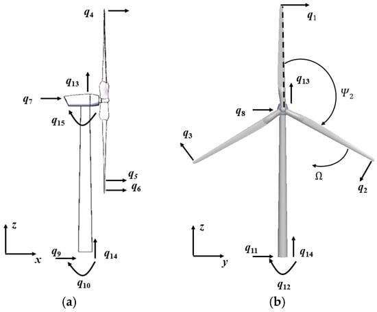
Figure 1.
15-DOF dimensionality reduction model of fixed wind turbine with (a) fore–aft direction and (b) side-to-side direction.
2. Materials and Methods
2.1. Construction of 15-DOF Dimensionality Reduction Dynamic Model
It can be seen from Figure 1 that each blade is related to two DOFs, qj and qj+3, with j = 1, 2, 3, indicating the edgewise and flapwise tip displacements, respectively. The tower-top translational motions are defined by the DOFs q7 and q8, indicating the fore–aft and side-to-side vibrations, respectively. The foundation rotational motions are represented by q10 and q12, indicating the fore–aft and side-to-side vibrations, respectively. The foundation translational motions are represented by q9 and q11, indicating the fore–aft and side-to-side vibrations, respectively. The vertical motion of the tower top is represented by q13. The foundation vertical motion is represented by q14. The fore–aft rotation at the tower top is represented by q15. Ω is the rotor speed. The azimuthal angle of blade j relative to the nacelle is written as
The Euler–Lagrange equation is used to construct the dimensionality reduction dynamic model of the fixed wind turbine:
where is a 15-dimensional DOF vector, is total kinetic energy, is total potential energy, and Q is the external dynamic load vector work conjugated to q, which is composed of the nonlinear loads, such as seismic load and wind load.
Figure 2 shows the detailed diagram of blade displacement. From Figure 2b, it can be seen that as the blade azimuth angle changes, the vertical dynamic response of the blade and the edgewise dynamic response of the blade interact with each other; that is, when external loads act in the vertical direction (such as vertical seismic motion), they will have an impact on the dynamic response of the blade edgewise direction.
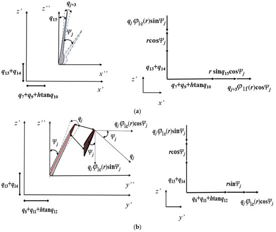
Figure 2.
Detailed diagram of blade absolute displacement with (a) fore–aft direction and (b) side-to-side direction.
Absolute displacement of each blade is shown in Figure 2 as follows:
where tanq10, tanq12, and sinq15 are simplified as q10, q12, and q15, respectively, and are the mode shape functions of the first edgewise and flapwise mode, respectively, h is the tower height, and r is the distance from the blade along the axial direction to the blade root.
The absolute velocity of the blade is as follows:
The composite absolute velocity of each blade is as follows:
Similarly, the absolute velocity between the nacelle and the hub is as follows:
Equations (10)–(12) allow for the following calculation of the nacelle and hub composite absolute velocity:
The absolute velocity of the tower is as follows:
where z is the distance from the tower along the axial direction to the tower root, and and are two types of normalized vibration mode functions of the tower.
The composite absolute velocity of the tower is as follows:
The system’s kinetic energy is defined as follows:
where = mnac + mhub is the total mass of the nacelle and hub, is the mass density of the tower, is the mass density of the blade, and are the foundation mass and moment of inertia, and R is the blade length.
As illustrated in Figure 3, the bending strain energy, centrifugal effect, and gravitational potential energy of the blade must be taken into account when determining the potential energy of the blade.
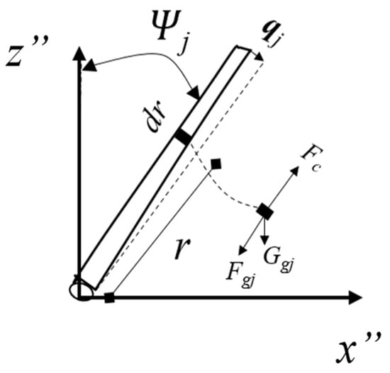
Figure 3.
Schematic diagram of blade potential energy.
The centrifugal force and gravity components of blade micro unit dr can be expressed as follows:
where ξ is the distance from r to R.
The total potential energy of the blade is
where and are the blade edgewise and flapwise bending stiffness, respectively.
The system’s potential energy is defined as follows:
where ktx(z) = kty(z) are the tower bending stiffness in both fore–aft and side-to-side directions, ktro(z) is the tower top corner stiffness, ktz(z) is the tensile stiffness of the tower, kxyphi is the rotational stiffness of the foundation, and kxyz is the translational stiffness of the foundation.
2.2. Structural Dynamic Equation Under Multidimensional Seismic Excitations
Substitution of Equations (18) and (22) into Equation (2) leads to the following structural dynamic equation:
where M is the mass matrix, C is the damping matrix, and K is the stiffness matrix.
where M is the symmetric matrix, and the elements in the upper right can be calculated using the expression in Appendix A.
The stiffness matrix K is
where the elements in K can be calculated using the expression in Appendix A.
The damping matrix is constructed using Rayleigh damping and expressed by
where a0 and b0 are the proportional coefficient, and their calculation formula is as follows:
where ζ is the damping ratio of the structure, and and are the 1st and 2nd natural frequencies of the structure.
In terms of the principles of work and energy, the generalized force can be determined as follows:
where W is the virtual work of external load and is derived in the following.
When deriving the generalized forces corresponding to seismic loads based on the principle of virtual work, it is first necessary to clarify the boundary conditions of the 15-DOF model:
- (1)
- Structural geometric boundaries.
The root of each blade is rigidly fixed to the hub, with only the 1st-order flapwise/edgewise DOFs (q1~q6) retained at the blade tip, and the bottom of the tower is elastically constrained to the foundation. The foundation retains translational degrees of freedom in the x/y/z directions and rotational DOFs around the x/y axes, with the constraint stiffness parameters shown in Table 2 used to simulate the soil–structure interaction.
Table 2.
Parameters employed in the 15-DOF fixed wind turbine model.
- (2)
- Load transfer boundaries.
Seismic excitation is transmitted to the superstructure only through the foundation, acting sequentially on the inertial masses of the foundation, tower, nacelle/hub, and blades.
- (3)
- Displacement constraint boundaries.
The virtual displacement at rigid connection locations (blade–hub, tower–nacelle–hub) is zero, while the virtual displacement at elastic constraint locations (tower–foundation) is directly associated with the generalized coordinates.
The acceleration of seismic loads in the x, y, and z directions is , , and , respectively. The virtual work generated by seismic loads on the blade, nacelle/hub, and tower is , , and ; the specific expressions are as follows:
The total virtual work is
Substituting Equation (32) into Equation (28) yields the generalized forces corresponding to an earthquake:
It should be noted that Equations (29)–(32) focus on calculating the virtual work of seismic inertial forces and do not directly include damping terms. This is because damping forces are “internal forces related to velocity,” and their contribution has already been integrated into the overall Equation (23) via the damping matrix C in Equation (26). The seismic generalized forces (as external force terms) and damping terms coexist independently in the equation.
Defining the state vector , Equation (23) can be expressed in the following state space manner:
where
3. Results and Discussions
3.1. Model and Seismic Excitation Selection
The NREL 5 MW fixed wind turbine is used to calibrate the proposed 15-DOF dimensionality reduction model [30]. The related data of the blades, the mass of the hub and nacelle, the distributed properties of the tower, the bending stiffness, and the mass per unit length of the blade are also given by Ref. [30]. Table 2 shows the main parameters of the 15-DOF fixed wind turbine.
, , , and are calculated using BModes_v3.00.0.exe software [31]:
Based on research experience in seismic design for the fixed wind turbine, and considering the site conditions of wind farms, the seismic fortification intensity of wind farm sites, and the frequency-domain characteristics of seismic excitations, the fixed wind turbine typical fundamental frequencies depend on the turbine size, and are typically in the range of 0.22–0.33 Hz [32]. This study is based on the actual site conditions of a wind farm in China. The wind farm should be classified as a Class B site, and the local fortification intensity is 7 degrees, corresponding to the seismic hazard having a probability of exceedance of 63% in 50 years. The Peak Ground Accelerations (PGAs) of all waves are set to 0.15 g [33]. Moreover, during the time history analysis, the PGAs should be modulated to 0.55 m/s2 [33]. Table 3 shows the seismic sequence number. Figure 4 shows the time histories and Fourier amplitude of seismic excitations. It can be seen from Figure 4 that the seven kinds of seismic waves have rich low-frequency characteristics.
Table 3.
Seismic sequence number.
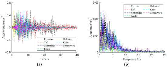
Figure 4.
Time histories and Fourier amplitude of seismic excitations: (a) time histories; (b) Fourier amplitude.
Then, to evaluate the validity and feasibility of the proposed 15-DOF model, comparisons of natural frequencies obtained from the present model and from the FAST program are carried out [30]. The agreement between FAST and the 15-DOF model is acceptable based on Table 4. Subsequently, a time-domain validation under seismic excitation (El Centro wave) is performed. The input direction of seismic motion is in the x-direction. The dynamic responses of the tower are directly compared with a detailed finite element model (as shown in Figure 5a). For the blades, a simplified thin-walled beam model, preserving equivalent mass distribution and flexural rigidity, is established for a feasible yet rigorous comparison (as shown in Figure 5b). The results, detailed in Figure 6, demonstrate excellent agreement in both cases, confirming the model’s accuracy.
Table 4.
Comparison of natural frequencies.
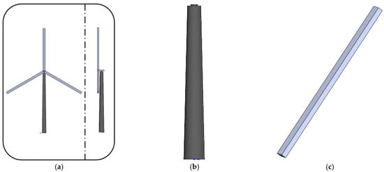
Figure 5.
Simplified finite element model of wind turbine with (a) integrated model, (b) tower model, and (c) blade model.
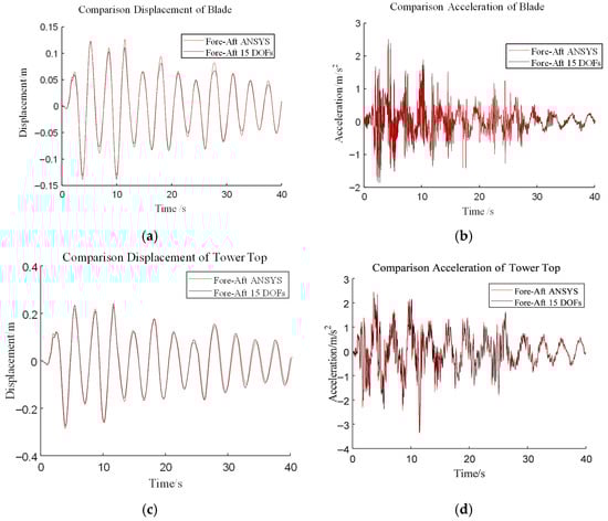
Figure 6.
Comparison of dynamic response time histories of the tip of the blade and top of the tower with (a) tip displacement of the blade, (b) tip acceleration of the blade, and (c) tower-top displacement and (d) acceleration.
3.2. Analysis of Wind Turbine Dynamic Response Based on Multidimensional Seismic Excitations
As shown in Table 5, Based on the above 15-DOF fixed wind turbine model and seismic excitations, five working cases are set up to analyze the influence of multidimensional seismic excitations on the dynamic response of the fixed wind turbine, analyzing the effects of operating conditions under rated speed and parking conditions on it. In seismic dynamic response analysis, the seismic excitations in each direction are adjusted at a ratio of 1 (main horizontal direction): 0.85 (secondary horizontal direction): 0.65 (vertical direction) [32].
Table 5.
Different operating conditions.
The dynamic response time histories of the tip-of-blade flapwise direction and tower-top fore–aft direction based on different working cases under ‘El Centro wave’ are shown in Figure 7. Applying multi-directional seismic excitations to the structure has no effect on the dynamic responses of the tip-of-blade flapwise direction and tower-top fore–aft direction.
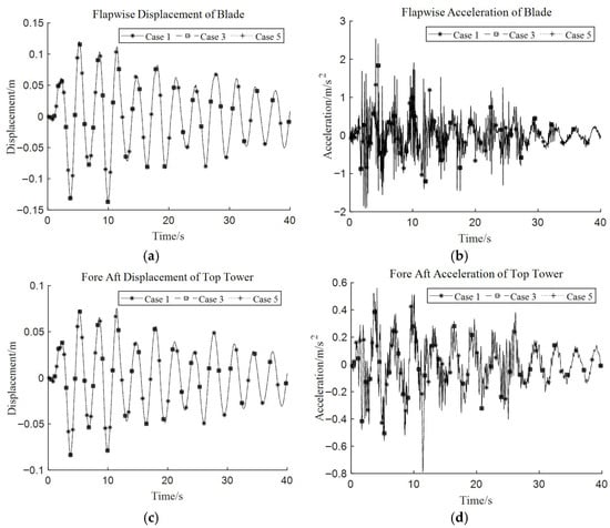
Figure 7.
Dynamic response time histories of blade flapwise direction and tower-top fore–aft direction in ‘El Centro wave’ with (a) tip displacement of blade, (b) tip acceleration of blade, and (c) tower-top displacement and (d) acceleration.
In Figure 8, only x-direction seismic excitations, xy-direction seismic excitations, and xyz-direction seismic excitations are applied to the structure, respectively. The peak displacement response of the tip-of-blade flapwise direction is 0.138 m under the ‘El Centro wave’; 0.04 m under the ‘Taft wave’; 0.033 m under the ‘Northridge wave’; 0.019 m under the ‘Friuli wave’; 0.023 m under the ‘Hollister wave’; 0.028 m under the ‘Kobe wave’; and 0.069 m under the ‘Loma Prieta wave’. The peak acceleration response of the tip-of-blade flapwise direction is 2.532 m/s2 under the ‘El Centro wave’; 1.861 m/s2 under the ‘Taft wave’; 2.438 m/s2 under the ‘Northridge wave’; 5.694 m/s2 under the ‘Friuli wave’; 0.99 m/s2 under the ‘Hollister wave’; 2.373 m/s2 under the ‘Kobe wave’; and 3.883 m/s2 under the ‘Loma Prieta wave’. It is shown that the dynamic responses of the tip-of-blade flapwise direction do not change after the seismic excitations are applied to the structure in the y-direction and z-direction, respectively.
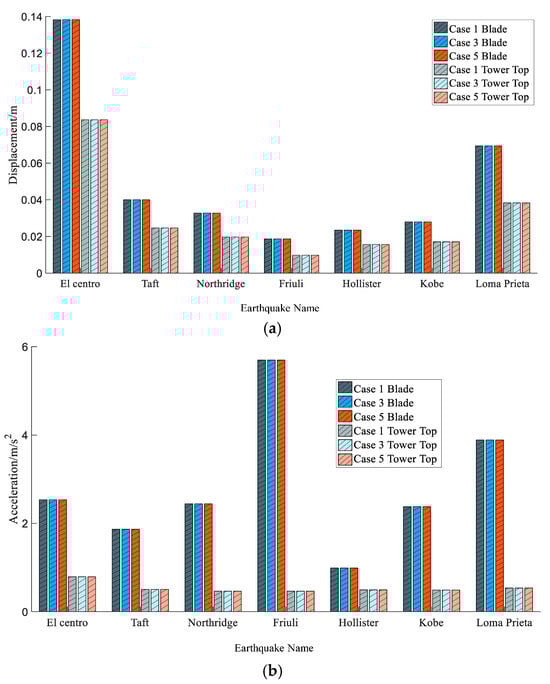
Figure 8.
Comparison of peak values of tip-of-blade flapwise and tower-top fore–aft directions with (a) displacement and (b) acceleration.
Considering the ‘El Centro wave’ as exterior excitation, the dynamic response time histories of the tip of the blade and tower top under case 2, case 4, and case 6 are shown in Figure 9. Applying multi-directional seismic excitations to the structure has no effect on the dynamic response of the tower-top side-to-side direction, but there is an increase in the tip-of-blade edgewise direction.
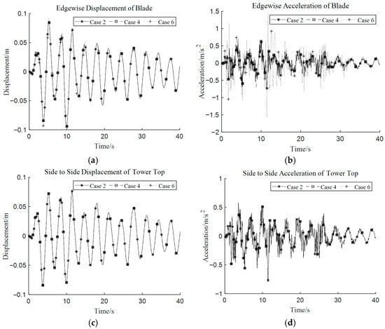
Figure 9.
Dynamic response time histories of blade edgewise direction and tower-top side-to-side direction under ‘El Centro wave’ with (a) tip-of-blade displacement, (b) tip-of-blade acceleration, (c) tower-top displacement, and (d) tower-top acceleration.
Figure 10 shows the comparison of peak values of tip-of-blade edgewise direction and tower-top side-to-side direction dynamic responses under case 2, case 4, and case 6. From Figure 8, it can be seen that when applying xy-direction seismic excitations to the structure, the dynamic response in the tip-of-blade edgewise direction does not increase. However, when applying xyz-direction seismic excitations to the structure, the peak displacement in the tip-of-blade edgewise direction is increased by 1.34–48.45%, and the peak acceleration is increased by 63.41–161.17%. These indicate that seismic excitations in the z-direction will increase the dynamic response of the tip-of-blade edgewise direction.
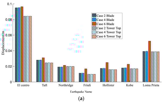
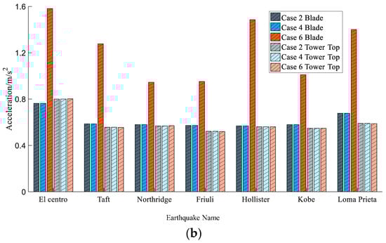
Figure 10.
Comparison of peak values of blade edgewise direction and tower-top side-to-side direction with (a) displacement and (b) acceleration.
Figure 11 provides the dynamic response time histories of the tip of the blade under case 3/4 and case 5/6. During the whole time histories, the dynamic response of the tip-of-blade flapwise direction is greater than that of the edgewise direction.
Figure 11.
Dynamic response time histories of the tip of the blade in the ‘El Centro wave’ with (a) cases 3 and 4, and (b) cases 5 and 6.
Figure 12 and Figure 13 indicate that when the xy-direction seismic excitations are applied to the fixed wind turbine, and the x-direction and y-direction are, respectively, set as the main direction, the peak displacement of the tip-of-blade edgewise direction is 17.55–64.93% smaller than that of the flapwise direction, and the acceleration is 63.02–91.47% smaller than that of the flapwise direction. When the xyz-direction seismic excitations are applied to the fixed wind turbine, the peak displacement of the blade edgewise direction is 4.28–50.0% smaller than that of the flapwise direction. The acceleration peak value of the blade edgewise direction is 19.50–83.94% smaller than that of the flapwise direction. The dynamic response peak of the tip-of-blade edgewise direction is smaller than that of the tip-of-blade flapwise direction. The reason is that the stiffness difference between the blade flapwise direction and the edgewise direction will lead to the anisotropy of the dynamic characteristics of the tip of the blade. The stiffness of the blade flapwise direction is always lower than that of the edgewise direction, and the flapwise direction with low stiffness is more prone to displacement and acceleration, which is the core reason for the difference.
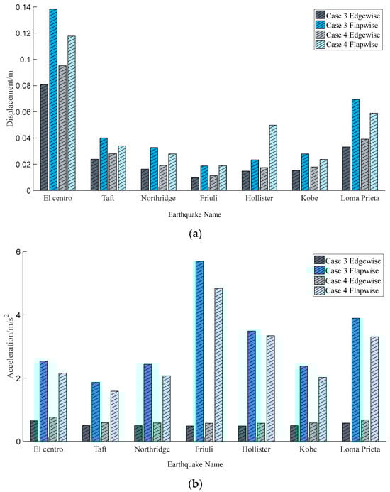
Figure 12.
Comparison of peak values of tip-of-blade dynamic response with (a) displacement and (b) acceleration.
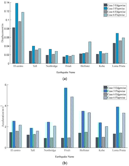
Figure 13.
Comparison of peak values of blade dynamic response with (a) displacement and (b) acceleration.
Figure 14 shows that the vertical dynamic response at the tower top is significantly smaller than the horizontal dynamic response after the xyz-direction seismic excitations are applied. The peak values of the vertical displacement dynamic responses are 0.072–0.50% of the horizontal direction, and the peak values of the vertical acceleration dynamic responses are 5.01–14.42% of the horizontal direction. The vertical seismic excitations have little influence on the vertical displacement of the tower top, and an obvious influence on the vertical acceleration response of the tower top.
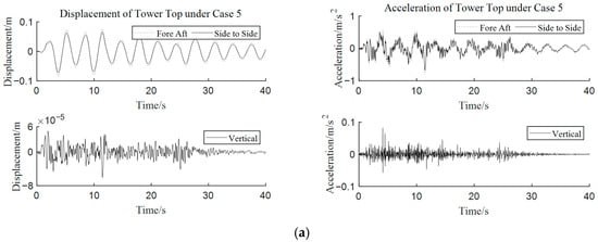
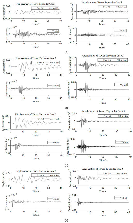
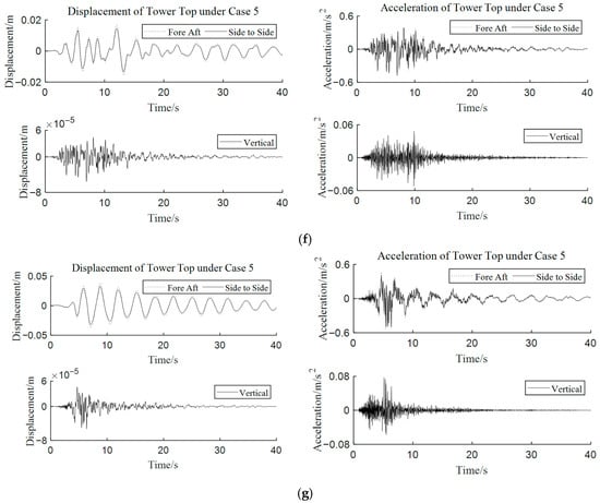
Figure 14.
Dynamic response time histories of the horizontal and vertical directions at the tower top under case 5 with (a) El Centro, (b) Taft, (c) Northridge, (d) Friuli, (e) Hollister, (f) Kobe, and (g) Loma Prieta.
3.3. Multidimensional Seismic Excitation Response in Different Operational Conditions
According to the previous section’s examination of the dynamic response of wind turbines under multidimensional seismic excitations, case 5 is the worst operating condition. As a result, the influence of fixed wind turbine operation on the dynamic response of the fixed wind turbine is examined using case 5. After referring to the fixed wind turbine design specifications [34], the seismic analysis conditions for fixed wind turbines are determined as follows:
- (1)
- Seismic excitations + structure in rated speed condition;
- (2)
- Seismic excitations + structure in parking condition.
From Figure 15, it can be seen that under multidimensional seismic excitation, the operating state of a fixed offshore wind turbine has a significant impact on the dynamic response of the blade tip, but has no significant effect on the displacement response of the tower top and blade tip. In the blade flapwise direction, the parking condition is the most unfavorable working condition. Compared with the rated speed condition, the peak acceleration in the flapwise direction of the blade tip increased by 149.95–365.51%. In the blade flapwise direction, the rated speed condition is the most unfavorable condition. Compared with the parking condition, the peak acceleration in the blade tip flapwise direction increased by 67.91–180.39%. From the calculation formula of the elements related to the flapwise direction in the structural stiffness matrix K in Appendix A, it can be seen that when the wind turbine is at rated speed, the gravity component will be generated, which is the reason that the rated speed is the most unfavorable operating condition in the flapwise direction. The influence of rated speed on the blade edgewise direction is reflected in two aspects: firstly, the formula for the seismic generalized force in the blade edgewise direction is related to rotational speed; secondly, the formula for the blade flapwise direction in the stiffness matrix K contains two terms related to rotational speed—though one is positive and the other is negative, rotational speed still reduces the stiffness of the edgewise direction after calculation. Therefore, the blade edgewise direction is in the most unfavorable operating condition at rated rotational speed.
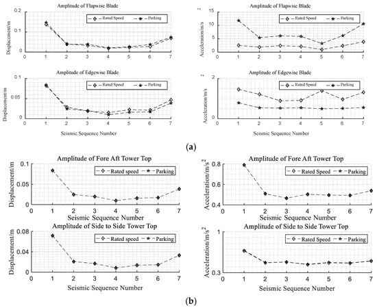
Figure 15.
Peak value of tip of blade and tower top for each earthquake serial number: (a) tip of blade and (b) tower top.
Acceleration amplitude spectra of the tip-of-blade edgewise and flapwise directions are shown in Figure 16. It can be found that the rotor speed has a promoting effect on the acceleration dynamic response of the tip-of-blade flapwise direction, and the rotor speed has an inhibitory effect on the acceleration of the tip-of-blade edgewise direction.
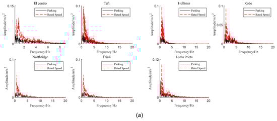
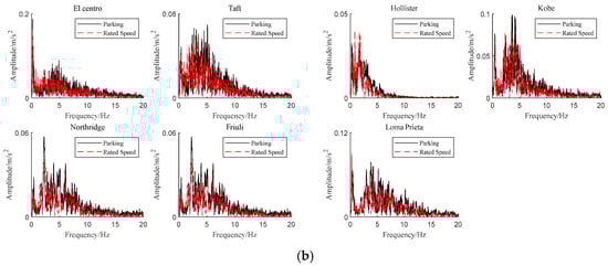
Figure 16.
Acceleration amplitude spectra of tip of blade with (a) edgewise direction and (b) flapwise direction.
4. Conclusions
Based on the Euler–Lagrange equation, a 15-DOF fixed wind turbine model is proposed. The NREL 5 MW fixed wind turbine is taken as the research object, and the modal response obtained by the FAST platform is compared to verify the correctness of the proposed dimensionality reduction model; the relative error of its natural frequencies is 0.128–7.820%. Considering the rated speed condition and parking condition of the fixed wind turbine, the dynamic response of the fixed wind turbine under multidimensional seismic excitations is studied. Through the analysis of parameters such as dynamic response of the blade and tower, the key conclusions can be summarized as follows:
The dynamic response of the tip of the blade in the flapwise direction is greater than that in the edgewise direction, which is independent of the loading position in the main direction of the seismic excitations. The maximum displacement difference is 64.93%, and the maximum acceleration difference is 91.47%. After the vertical seismic excitations are applied, the maximum displacement of the tip-of-blade flapwise direction is increased by 48.45%, and the maximum acceleration is increased by 161.17%, indicating that the vertical seismic excitations will cause an increase in the dynamic response of the tip-of-blade edgewise direction. The peak vertical displacement at the tower top is 0.072–0.50% of the horizontal direction, and the peak vertical acceleration is 5.09–14.41% of the horizontal direction. Because the nacelle at the top of the tower usually contains sophisticated electronic instruments and equipment, minimal vibration may also affect it. Therefore, the vertical dynamic response cannot be ignored. The addition of control devices in the nacelle to suppress its excessive dynamic response can be considered.
Under the action of multidimensional seismic excitations, the operating state of the fixed wind turbine has no significant effect on the dynamic response of the tower, while the dynamic response of the blade is significantly affected, especially the acceleration response. In the tip-of-blade edgewise direction, the rated speed state is the worst operating condition. Compared with the parking state, the maximum value of tip-of-blade edgewise acceleration is increased by 180.36%. In the tip-of-blade flapwise direction, the parking state is the worst operating condition. Compared with the rated speed state, the maximum value of tip-of-blade flapwise acceleration is increased by 365.51%.
The findings highlighted in this article reveal the differences in the dynamic response of wind turbines under multidimensional seismic motion and different operating conditions. Given the unpredictability of seismic waves, it is necessary to take subsequent control measures; otherwise, based on the analysis of our existing dynamic response results, it may be difficult to guarantee the safety of wind turbines. This can provide reference for the design of wind turbines in earthquake-prone areas. Based on this study, wind turbine dynamic response under multi-field coupling (e.g., wind–wave–earthquake, etc.) and corresponding vibration control measures (such as a tuned mass damper or tuned mass damper inerter, which, due to its small travel distance and high output, is more suitable for small spaces inside the cabin to control vertical seismic effects) will be the focus of subsequent research.
Author Contributions
Conceptualization, Z.L.; methodology, Z.L.; software, C.X.; validation, C.X. and W.L.; formal analysis, C.X.; investigation, X.L.; resources, X.L.; data curation, W.L.; writing—original draft preparation, C.X.; writing—review and editing, Z.L.; visualization, W.L.; supervision, X.L.; project administration, Z.L.; funding acquisition, Z.L. All authors have read and agreed to the published version of the manuscript.
Funding
This research was funded by the Key Technology Research and Development Program of Shaanxi Province of China under grant number 2024GX-YBXM-235, and Key Scientific Research Program of Education Department of Shaanxi Province of China under grant number 24JS018.
Data Availability Statement
The data presented in this study are available on request from the corresponding author on reasonable request. The data are not publicly available due to privacy policies.
Conflicts of Interest
The authors declare no conflicts of interest.
Appendix A
References
- Global Wind Energy Council. Global Wind Report 2024. Available online: https://www.gwec.net/reports/globaloffshorewindreport/2024 (accessed on 1 July 2024).
- Lai, Y.; Li, W.; He, B.; Xiong, G.; Xi, R.; Wang, P. Influence of blade flexibility on the dynamic behaviors of monopile-supported offshore wind turbines. J. Mar. Sci. Eng. 2023, 11, 2041. [Google Scholar] [CrossRef]
- Lotfizadeh, O. Life Cycle Assessment of Offshore Wind Farms–A Comparative Study of Floating vs. Fixed Offshore Wind Turbines. Master’s Thesis, University of South-Eastern Norway, Kongsberg, Norway, 2024. [Google Scholar]
- Zhang, T.; Wang, W.; Li, X.; Wang, B. Vibration mitigation in offshore wind turbine under combined wind-wave-earthquake loads using the tuned mass damper inerter. Renew. Energy 2023, 216, 119050. [Google Scholar] [CrossRef]
- EN 61400-3:2009; Wind Turbines—Part 3: Design Requirements for Fixed Wind Turbines. IEC: Geneva, Switzerland, 2009.
- Det Norske Veritas (DNV). DNV-OS-J101: Design of Fixed Wind Turbine Structures; DNV: Copenhagen, Denmark, 2014. [Google Scholar]
- Katsanos, E.I.; Thöns, S.; Georgakis, C.Τ. Wind turbines and seismic hazard: A state-of-the-art review. Wind Energy 2016, 19, 2113–2133. [Google Scholar] [CrossRef]
- Wang, L.; Kolios, A.; Liu, X.; Venetsanos, D.; Cai, R. Reliability of fixed wind turbine support structures: A state-of-the-art review. Renew. Sustain. Energy Rev. 2022, 161, 112250. [Google Scholar] [CrossRef]
- Kjørlaug, R.A.; Kaynia, A.M. Vertical earthquake response of megawatt-sized wind turbine with soil-structure interaction effects. Earthq. Eng. Struct. Dyn. 2015, 44, 2341–2358. [Google Scholar] [CrossRef]
- He, K.; Ye, J. Seismic dynamics of offshore wind turbine-seabed foundation: Insights from a numerical study. Renew. Energy 2023, 205, 200–221. [Google Scholar] [CrossRef]
- Cheng, X.; Wang, T.; Zhang, J.; Wang, P.; Tu, W.; Li, W. Dynamic response analysis of monopile fixed wind turbines to seismic and environmental loading considering the stiffness degradation of clay. Comput. Geotech. 2023, 155, 105210. [Google Scholar] [CrossRef]
- Xu, M.; Au, F.T.; Wang, S.; Wang, Z.; Peng, Q.; Tian, H. Dynamic response analysis of a real-world operating fixed wind turbine under earthquake excitations. Ocean Eng. 2022, 266, 112791. [Google Scholar] [CrossRef]
- van der Valk, P.L.C.; Voormeeren, S.N. An overview of modeling approaches for complex fixed wind turbine support structures. In Proceedings of the ISMA2012-USD2012, Leuven, Belgium, 17–19 September 2012; pp. 17–19. [Google Scholar]
- Flodén, O.; Persson, K.; Sandberg, G. Reduction methods for the dynamic analysis of substructure models of lightweight building structures. Comput. Struct. 2014, 138, 49–61. [Google Scholar] [CrossRef]
- Banerjee, A.; Chakraborty, T.; Matsagar, V.; Achmus, M. Dynamic analysis of an offshore wind turbine under random wind and wave excitation with soil-structure interaction and blade tower coupling. Soil Dyn. Earthq. Eng. 2019, 125, 105699. [Google Scholar] [CrossRef]
- Wang, P.; Zhao, M.; Du, X.; Liu, J.; Xu, C. Wind, wave and earthquake responses of offshore wind turbine on monopile foundation in clay. Soil Dyn. Earthq. Eng. 2018, 113, 47–57. [Google Scholar] [CrossRef]
- Lavassas, I.; Nikolaidis, G.; Zervas, P.; Efthimiou, E.; Doudoumis, I.N.; Baniotopoulos, C.C. Analysis and design of the prototype of a steel 1-MW wind turbine tower. Eng. Struct. 2003, 25, 1097–1106. [Google Scholar] [CrossRef]
- Fitzgerald, B.; Basu, B.; Nielsen, S.R. Active tuned mass dampers for control of in-plane vibrations of wind turbine blades. Struct. Control Health Monit. 2013, 20, 1377–1396. [Google Scholar] [CrossRef]
- Zhang, J.W.; Liang, X.; Wang, L.Z.; Wang, B.X.; Wang, L.L. The influence of tuned mass dampers on vibration control of monopile offshore wind turbines under wind-wave loadings. Ocean Eng. 2023, 278, 114394. [Google Scholar] [CrossRef]
- Yang, Y.; Bashir, M.; Li, C.; Michailides, C.; Wang, J. Mitigation of coupled wind-wave-earthquake responses of a 10 MW fixed-bottom offshore wind turbine. Renew. Energy 2020, 157, 1171–1184. [Google Scholar] [CrossRef]
- Xu, X.; Wang, F.; Gaidai, O.; Naess, A.; Xing, Y.; Wang, J. Bivariate statistics of floating offshore wind turbine dynamic response under operational conditions. Ocean Eng. 2022, 257, 111657. [Google Scholar] [CrossRef]
- Kim, D.H.; Lee, S.G.; Lee, I.K. Seismic fragility analysis of 5 MW offshore wind turbine. Renew. Energy 2014, 65, 250–256. [Google Scholar] [CrossRef]
- Asareh, M.A.; Schonberg, W.; Volz, J. Effects of seismic and aerodynamic load interaction on structural dynamic response of multi-megawatt utility scale horizontal axis wind turbines. Renew. Energy 2016, 86, 49–58. [Google Scholar] [CrossRef]
- Asareh, M.A.; Schonberg, W.; Volz, J. Fragility analysis of a 5-MW NREL wind turbine considering aero-elastic and seismic interaction using finite element method. Finite Elem. Anal. Des. 2016, 120, 57–67. [Google Scholar] [CrossRef]
- Patil, A.; Jung, S.; Kwon, O.S. Structural performance of a parked wind turbine tower subjected to strong ground motions. Eng. Struct. 2016, 120, 92–102. [Google Scholar] [CrossRef]
- Yuan, C.; Chen, J.; Li, J.; Xu, Q. Fragility analysis of large-scale wind turbines under the combination of seismic and aerodynamic loads. Renew. Energy 2017, 113, 1122–1134. [Google Scholar] [CrossRef]
- Johansson, J.; Kaynia, A. Equivalent linear pseudostatic and dynamic modelling of vertically vibrating monopile. Mar. Struct. 2021, 75, 1–14. [Google Scholar] [CrossRef]
- Elmas, F.; Algin, H.M. Soil-monopile interaction assessment of offshore wind turbines with comprehensive subsurface modelling to earthquake and environmental loads of wind and wave. Soil Dyn. Earthq. Eng. 2025, 192, 102870. [Google Scholar] [CrossRef]
- Cui, C.; Meng, K.; Xu, C.; Liang, Z.; Li, H.; Pei, H. Analytical solution for longitudinal vibration of a floating pile in saturated porous media based on a fictitious saturated soil pile model. Comput. Geotech. 2021, 131, 103942. [Google Scholar] [CrossRef]
- Jonkman, J.; Butterfield, S.; Musial, W.; Scott, G. Definition of a 5-MW Reference Wind Turbine for Offshore System Development; Technical Report No. NREL/TP-500-38060; National Renewable Energy Laboratory: Golden, CO, USA, 2009. [Google Scholar]
- Bir, G. Blades and towers modal analysis code (BModes): Verification of blade modal analysis capability. In Proceedings of the 47th AIAA Aerospace Sciences Meeting Including the New Horizons Forum and Aerospace Exposition, Orlando, FL, USA, 5–8 January 2009; p. 1035. [Google Scholar]
- Bhattacharya, S.; De Risi, R.; Lombardi, D.; Ali, A.; Demirci, H.E.; Haldar, S. On the seismic analysis and design of offshore wind turbines. Soil Dyn. Earthq. Eng. 2021, 145, 106692. [Google Scholar] [CrossRef]
- GB50011-2010; Chinese Code for Seismic Design of Buildings. Ministry of Construction of Peoples Republic of China: Beijing, China, 2010. (In Chinese)
- Woebbeking, M.; Argyriadis, K. New guidelines for the certification of fixed wind turbines. In Proceedings of the ISOPE International Ocean and Polar Engineering Conference, Anchorage, AK, USA, 30 June–5 July 2013. [Google Scholar]
Disclaimer/Publisher’s Note: The statements, opinions and data contained in all publications are solely those of the individual author(s) and contributor(s) and not of MDPI and/or the editor(s). MDPI and/or the editor(s) disclaim responsibility for any injury to people or property resulting from any ideas, methods, instructions or products referred to in the content. |
© 2025 by the authors. Licensee MDPI, Basel, Switzerland. This article is an open access article distributed under the terms and conditions of the Creative Commons Attribution (CC BY) license (https://creativecommons.org/licenses/by/4.0/).