Abstract
This paper presents the outcomes of an extensive experimental investigation on the seismic performance of an innovative exoskeleton retrofitting system, developed as part of the ERIES-RESUME project. The proposed system integrates laminated timber and aluminium components to enhance the structural resilience of existing reinforced concrete (RC) buildings, while also offering the potential for thermal upgrading. Two identical 1:3 scale RC models, representing typical non-ductile structures, were tested on a shaking table at the IZIIS Laboratory of the Institute of Earthquake Engineering and Engineering Seismology in Skopje. The first model, initially unstrengthened, was subjected to seismic loads until significant structural and infill-wall damage was reached. Following appropriate repairs, the exoskeleton was applied, and the model was retested. The second model was equipped with an exoskeleton from the outset. Test results demonstrate significant improvements in seismic performance, including increased stiffness, reduced interstory drifts, reduced acceleration amplification, and reduced infill wall damage. The study confirms the feasibility and effectiveness of the proposed exoskeleton system as a practical solution for retrofitting vulnerable reinforced concrete buildings.
1. Introduction
Growing awareness of the seismic vulnerability and energy inefficiency of aging buildings, particularly in earthquake-prone regions, has intensified the need for integrated retrofitting strategies. Many outdated masonry and reinforced concrete (RC) structures, built before the introduction of modern seismic codes, present serious risks during seismic events [1,2,3]. Consequently, enhancing both structural safety and energy performance has become a paramount priority in academic research and public policy.
Several European countries in the Mediterranean area have experienced firsthand the devastating impact of earthquakes. In addition to seismic vulnerability, low energy efficiency represents another widespread challenge for existing masonry and RC buildings. In the current climate-crisis scenario, increased energy demand, particularly for heating and cooling, results in higher operational costs and contributes to greenhouse gas emissions. Estimates indicate that the building sector accounts for around 35% of total global energy consumption and 38% of greenhouse gas emissions [4]. To address these challenges, a range of national and regional policies have been adopted. The European Union, through the European Green Deal, actively promotes large-scale renovation programs aimed at reducing energy demand and improving environmental performance [5]. Similar initiatives are being implemented in other regions, such as China [6], India [7], the United States, and the United Kingdom [8,9]. Against this background, rising energy costs and global efforts toward sustainability underscore the importance of combining energy-efficient solutions with seismic upgrades. Studies have shown that integrated retrofitting approaches not only improve a building’s resilience and thermal efficiency but also tend to be more economically viable than isolated interventions [10].
To meet these dual challenges, numerous hybrid retrofitting strategies have been developed. One of the solutions is to employ fibre- or textile-reinforced mortars combined with external insulation, providing both structural strengthening and thermal upgrading [11,12,13]. Parallel to these approaches, timber-based façade systems, such as laminated or prefabricated timber panels applied externally to RC frames, have shown the ability to improve stiffness, architectural quality, and energy performance within a single intervention [14,15,16]. A widely adopted concept consists of installing external reinforcement layers on building façades together with thermal insulation. Several configurations have evolved from this approach, including cast-in-place RC walls formed using insulating formwork [10,17], timber–cement composite panels offering both structural and thermal enhancement [18], and cold-formed steel exoskeletons with diagonal bracing to increase lateral resistance while accommodating insulation layers [19], as well as other configurations of steel exoskeletons [20,21,22]. In addition to these systems, growing attention has been directed toward metal shear-panel retrofits, particularly those made of aluminium, which offer low self-weight, high deformability, and efficient energy dissipation. Recent studies demonstrate that aluminium shear panels can markedly improve the seismic performance of existing RC frames and integrate effectively within façade-based energy retrofit strategies [23,24].
This study contributes to the field by assessing the performance of an innovative exoskeleton retrofitting system consisting of laminated timber and aluminium panels applied to a reinforced concrete building tested on a shaking table. In addition to enhancing seismic resistance and ductility, the aluminium panels are coupled with bio-based insulating layers (e.g., cork, hemp), offering the possibility of improving the building’s thermal performance, thereby supporting energy efficiency and climate resilience against heat waves and cold extremes. However, thermal performance is not assessed in this study and is not a focus of the present work.
The experimental phase involves shaking table tests conducted at the IZIIS Laboratory in Skopje, using two identical 1:3 scale reinforced concrete (RC) structures with equivalent geometric and mechanical properties [25]. The first specimen, initially tested without reinforcement, serves as the baseline model. After undergoing appropriate repairs, this specimen is retrofitted with the exoskeleton system to assess its seismic performance enhancement under renewed testing. In parallel, the second specimen, representing an undamaged existing structure, is directly equipped with the exoskeleton system to evaluate its effectiveness on the intact model. The primary objective is to assess the seismic improvement provided by the exoskeleton in both retrofit scenarios, thereby evaluating its feasibility and effectiveness as a practical seismic upgrading solution for existing RC buildings.
The novelty of this work lies in three aspects: (i) introducing a hybrid timber–aluminium exoskeleton that broadens current façade-based retrofit concepts; (ii) establishing a controlled framework for evaluating its performance under different initial structural conditions; and (iii) providing new evidence on how pre-existing damage affects retrofit effectiveness, addressing a gap in current seismic rehabilitation research.
2. The Structures Under Study
2.1. The 3D RC Frames
At the Institute of Earthquake Engineering and Engineering Seismology (IZIIS) in Skopje, a comprehensive full-scale experimental program was carried out to test and validate 1:3 scale structural models. These models represent typical reinforced concrete (RC) frames commonly found in structures that were not designed in accordance with modern seismic codes. In particular, the RC prototypes were designed to replicate typical pre-1970s non-ductile concrete buildings in Southern Europe, characterized by the absence of capacity-design principles, frames resisting laterally in only one direction, and limited and widely spaced transverse reinforcement.
Each model was constructed as a two-story system, having a total length of 4.2 m along its longitudinal axis. The ground story height is 1.5 m, while the upper story measures 1 m. The structural system is defined by two longitudinal RC frames with a spacing of 1.4 m, connected in the transverse direction by the RC slab and edge beams. The model was established on reinforced concrete strip footings, with cross-sectional dimensions of 85 × 25 cm in the longitudinal direction, reinforced with 11Ø10 bars in both top and bottom zones, and 80 × 25 cm at the transverse ends, reinforced with 10Ø10 bars, providing stable support and uniform load transfer to the testing platform. All footings included Ø4 stirrups spaced at 10 cm.
Beams and columns had cross-sections of 10 × 15 cm and 10 × 10 cm, respectively. Both elements were reinforced longitudinally with 8 mm diameter bars positioned at the corners, while the transverse reinforcement consisted of 4 mm diameter stirrups spaced every 10 cm. Infill walls made of hollow bricks were placed only in the end bays along the longitudinal direction. Two reinforced concrete slabs were cast between the longitudinal frames, positioned at heights of 1.5 m and 2.5 m.
Both slabs had a thickness of 6 cm and were reinforced with 6 mm diameter bars spaced at 7 cm in both orthogonal directions, placed in both the top and bottom reinforcement zones. Construction drawings are provided in Figure 1.
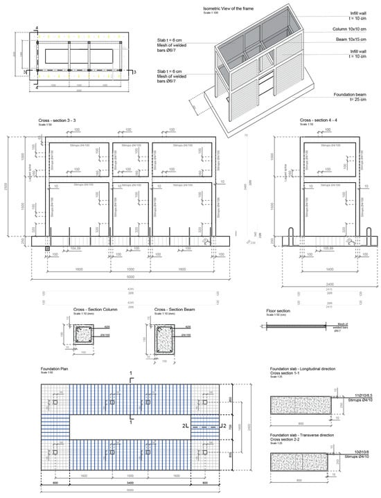
Figure 1.
Construction drawings for the RC structure.
The lower slab included an opening in the central bay to allow access for instrumentation and testing, while the upper slab spanned the entire floor area. To simulate vertical loads, eight steel ingots weighing 400 kg each were placed on top of the upper slab, resulting in a total added weight of 3200 kg.
2.2. The Exoskeleton System
The proposed strengthening system combined Gl24h laminated timber frames and aluminium alloy shear walls as the main structural materials. Timber frames were connected using galvanized steel plates and screws. The system was anchored to the existing reinforced concrete structure with steel pins installed at the beam–column joints and at the foundation strips, ensuring a stable and flexible connection. The exoskeleton was installed on all exterior façades, except for the central longitudinal bay, which remained uncovered to allow for visual inspection and monitoring during testing.
A key component of the system is the use of 2 mm thick aluminium shear panels, which act like structural shear walls. These panels improve the seismic performance by increasing stiffness and limiting lateral deformations.
Galvanized steel angles were used to connect the aluminium panels to the timber frame. These connections also allow for the installation of recycled cork insulation panels, which enhance thermal performance and contribute to environmental sustainability. All the connections were verified according to the relevant Eurocodes and Italian Technical Code. The insulation layer was a 10 mm thick pure expanded cork panel having a density of 108–120 kg/m3 and a thermal conductivity of 0.0375 W/mK according to the technical data sheet of the producer. The configuration and details of the exoskeleton system are reported in Figure 2.
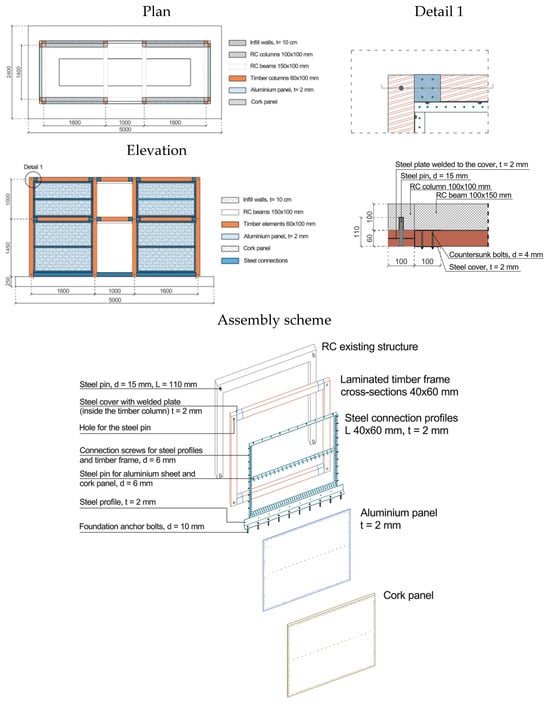
Figure 2.
Construction drawings for the exoskeleton system (units: mm).
2.3. Material Properties of the Structural and Retrofitting Components
Table 1 provides a summary of the mechanical properties of the materials used in the experimental model and the exoskeleton system. The listed values are based on laboratory tests conducted as part of the experimental campaign and include the properties of the reinforcement bars, aluminium panels, steel connectors, masonry units, mortar, and concrete. Timber elements were not laboratory-tested and are therefore not included in the table.

Table 1.
Material mechanical properties.
2.4. Scaling Factors
The physical model was treated as an adequate replica with artificial mass simulation, following the principles of a lumped-mass system. The RC elements and the exoskeleton components were scaled according to the adopted similitude laws, while the seismic effective mass was introduced separately from the structural material. Since the model was built of concrete, the mass density could not be scaled to satisfy the theoretical ratio E/ρ. The structurally effective mass, therefore, accounted for 3.7% of the prototype mass. To improve the inertial similarity, steel ingots amounting to a total of 3.2 t were added on the roof slab as lumped masses, resulting in a total model mass equal to 5.0% of the prototype mass. The applied scaling factors are listed in Table 2.
Table 2.
Scaling factors.
3. The Experimental Activities
3.1. The Investigated Models
As part of the experimental study, two models, Model X and Model Y, were built with identical geometry and material properties. The testing was divided into three phases to evaluate the effectiveness of the exoskeleton system as a seismic strengthening method:
- Phase 1: The unstrengthened Model Y was subjected to increasing seismic loads until significant structural and infill-wall damage was observed.
- Phase 2: After the damage, the ground-floor infill masonry walls were rebuilt to restore the original configuration, while no strengthening was performed on the reinforced concrete members. The exoskeleton system was then applied to Model Y to assess its ability to restore strength, stiffness, and ductility, as well as its effectiveness in preventing infill wall overturning.
- Phase 3: Model X, which included the exoskeleton from the beginning, was tested under the same loading conditions to compare its performance with the retrofitted model.
Figure 3 shows the laboratory view during the construction of the two-twin scaled reinforced concrete building specimens, with Model Y on the left side of the image and Model X on the right.
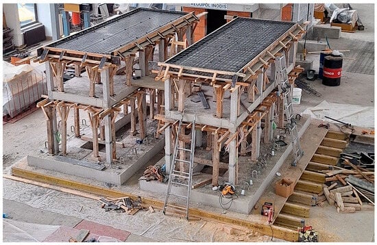
Figure 3.
Building of the RC structure.
Figure 4 shows, on the left, Model Y mounted on the shaking table during the preliminary testing phase, without the retrofitting system implemented, while on the right, it shows Model X, which is already equipped with the retrofitting system and ready for the subsequent testing stages.
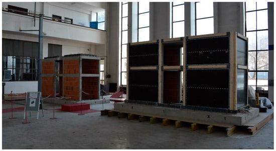
Figure 4.
Test models: Model Y (left), Model X (right).
3.2. Shaking Table and Instrumentation
The shake table tests were conducted at the Laboratory for Dynamic Testing within the Institute of Earthquake Engineering and Engineering Seismology (IZIIS) in Skopje, Republic of North Macedonia. The shake table, operational since 1980, consists of a 5.0 m × 5.0 m pre-stressed concrete waffle slab with a total weight of 33.0 tons, and is capable of carrying payloads of up to 40 tons. The system provides five degrees of freedom, enabled by two lateral and four vertical MTS hydraulic actuators, and is controlled using an MTS Digital Controller 469D (MTS Systems Corp., Eden Prairie, MN, USA). Data acquisition was performed using a PXI modular system, connected to multiple types of transducers. The software used for data acquisition was LabVIEW 2020 version 20.0f1.
To monitor the dynamic response of the models during testing, various sensors were installed, including accelerometers (ACCs), linear potentiometers (LPs), linear variable differential transformers (LVDTs), and strain gauges (SGs). These instruments were used to measure accelerations, absolute and relative displacements, and strains.
The instrumentation setup included 15 accelerometers, positioned at different heights and oriented in two horizontal directions. Four linear potentiometers were installed at the slab levels to capture interstory displacements. A total of 10 LVDTs were used, two placed between the model and the shake table, and eight positioned around the beam–column joints to monitor local deformations. For strain measurements, a total of 30 strain gauges were applied. Out of these, 24 were mounted on reinforcement bars within the columns at various heights, and 6 were installed directly on the concrete surface of the columns.
3.3. Testing Methodology
The experimental program consisted of a total of 66 tests, grouped into three phases. A consistent testing methodology was applied throughout all phases, involving two types of dynamic input: resonant frequency tests and seismic excitation tests.
The resonant frequency tests were used to evaluate the dynamic characteristics of the models. These were conducted in three key states: at the beginning of each phase (initial state), during the testing campaign (intermediate states), and at the end of each phase (final state), to monitor changes in the stiffness and integrity of the models.
To assess the seismic performance of the models under earthquake loading, three different ground motion records were used: (a) EQ1: Adana 1998 (Mw 6.3); (b) EQ2: Umbria 2016 (Mw 6.2); (c) EQ3: a synthetically generated earthquake based on the Eurocode 8 spectrum for Soil Type C.
All three input records (EQ1, EQ2, and EQ3) were selected based on their spectral shape and frequency content, as they are representative of the expected seismic demand for the assumed site conditions of the tested building typology. The ground motions were scaled according to the 1:3 similitude requirements of the physical model. Time scaling was applied following , while the amplitudes were adjusted to reach the target excitation levels used in each test phase.
The intensity levels used in the testing campaign (e.g., 75%, 100%, 120%, and 140%) represent amplitude scaling of the input acceleration record. The percentages indicate a direct multiplication of the original acceleration time history. For example, “120% EQ3” corresponds to the EQ3 input scaled by a factor of 1.20 in terms of its acceleration amplitude, including the PGA and all recorded acceleration values. A time history record of the synthetically generated ground motion (TH8) is presented in Figure 5.
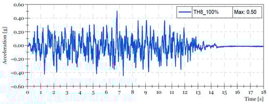
Figure 5.
Time history of the synthetically generated ground motion (TH8).
4. Results and Discussion
4.1. Phase 1 (Tests 1–19)
Phase 1 began with a sequence of random excitations (Tests 1–3) applied to Model Y with increasing amplitudes and a frequency range of 1–45 Hz, conducted to determine the initial dynamic characteristics of the bare frame. The dominant frequency recorded during this phase was approximately 10.2 Hz (Test 3).
The first seismic excitations were applied from Tests 4 to 6 using EQ1, EQ2, and EQ3, all at relatively low intensities (up to 0.13 g).
Between Tests 7 and 11, seismic inputs with increasing intensity were applied, ranging up to 75% of EQ3 (Test 10), combined with additional random tests to monitor frequency changes.
No significant response changes were observed until Test 12, where EQ3 was applied at 100%. This test marked the onset of visible damage, including moderate cracking of the bare frame and detachment of the infill walls.
Subsequent tests (13–15) included additional excitations, combining random input and EQ3 at 100%. The previously formed cracks remained visible and continued to develop.
Test 16 (120% EQ3) led to a noticeable increase in the extent of damage, with clearly visible cracks developing in the bare frame.
The highest level of observed damage occurred during Test 18 (140% EQ3), which resulted in extensive cracking and collapse of approximately 80% of the ground floor infill.
The final random excitation (Test 19) indicated a substantial reduction in the dominant frequency, which dropped to around 2.0 Hz, equivalent to a reduction of about 80% compared to the initial state.
Figure 6 presents the condition of Model Y after Phase 1.
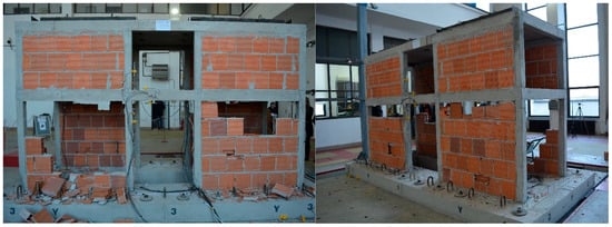
Figure 6.
Model Y after Phase 1.
Additionally, Figure 7 presents the time history comparison between the input acceleration at the shaking table (black line) and the output acceleration recorded by accelerometer ACC9 (red line) located at the top of Model Y during Test 18 (140% EQ3).
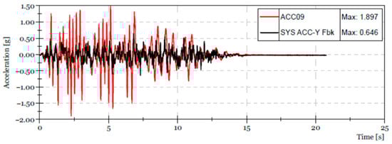
Figure 7.
Time history comparison of input and output accelerations during Test 18.
The results clearly indicate a strong amplification of the structural response, with the peak acceleration measured by ACC9 (1.897 g) being approximately three times higher than the maximum input acceleration (0.646 g). This amplification reflects the significant stiffness degradation of the bare frame and correlates well with the observed severe cracking and partial collapse of the ground floor infill walls.
4.2. Phase 2 (Tests 20–38)
Phase 2 began with a random excitation (Test 20) to assess the initial state of the Phase 1-damaged Model Y strengthened with the exoskeleton system. The dominant response frequency was recorded at 7.4 Hz, indicating a significant recovery in global stiffness compared to the end of Phase 1.
From Tests 21 to 25, seismic excitations were applied starting with EQ1 (15%), followed by EQ2 (10%), and subsequently EQ3 at intensity levels of 18%, 27%, and 50%. No visual damage was observed during this sequence, and the infill walls remained intact.
Tests 26 and 28 were random excitations used to monitor the evolution of the dynamic response. EQ3 was further applied at 75% and 100% in Tests 27 and 29, respectively. Up to this point, the model continued to perform without visible structural changes.
Following Test 31, in which EQ3 was applied at 120% (0.52 g), detachment of infill walls was observed along with the appearance of cracks in the bare frame. Although the damage was moderate, it marked the beginning of a reduction in stiffness and integrity.
Tests 32 to 37 included a combination of random and seismic inputs at increased intensity. The final seismic test in this phase (Test 37, conducted with EQ3 at 180% (0.90 g)) resulted in limited additional damage. Approximately 10% of the ground floor infill collapsed, while the exoskeleton system remained unaffected. The final random excitation (Test 38) indicated a reduction in the dominant frequency to approximately 4.8 Hz, representing about a 35% decrease compared to the initial state of Phase 2.
Figure 8 presents photographs of the structural condition after Phase 2. The images show localized cracking in the bare frame and partial detachment of infill walls.
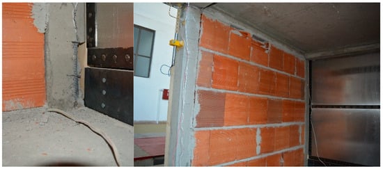
Figure 8.
Model Y after Phase 2.
In Figure 9, the time history comparison is shown between the input acceleration at the shaking table (black line) and the output acceleration recorded by accelerometer ACC11 (red line) during Test 37 (180% EQ3). The response demonstrates a pronounced amplification, with the peak acceleration at ACC11 (2.73 g) reaching nearly three times the maximum input acceleration (0.91 g). Accelerometer ACC11 was positioned at the top of the model, diagonally with respect to ACC9. This amplification highlights the effectiveness of the exoskeleton system in constraining damage progression, as only limited additional cracking was observed while the overall structural integrity was maintained.
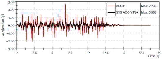
Figure 9.
Time history comparison of input and output accelerations during Test 37.
4.3. Phase 3 (Tests 39–66)
Phase 3 began with a random excitation (Test 39) to define the initial state of the second model, which was equipped with the exoskeleton system from the start. The recorded dominant frequency at this point was approximately 11.9 Hz.
From Tests 40–44, seismic inputs from different ground motions (EQ1, EQ2, and EQ3) were applied at intensity levels between 10% and 50%, and the structural response remained stable, with no visible damage to the bare frame or infill walls. Tests 45, 46, and 48 were random excitations used for frequency tracking, with the measured dominant frequency remaining close to the initial value observed at the beginning of this phase.
EQ3 was applied at 100% in Test 49, followed by Test 50, where the frequency dropped to 10.6 Hz. Up to Test 51 (120% EQ3), only small cracks were observed in the mortar joints between infill elements, with a corresponding frequency of 9.9 Hz. After Test 53 (140% EQ3), detachment of the infill walls was observed, along with shallow cracking near the joints of two corner columns.
Test 54 was a random excitation for tracking, after which Test 55 (160% EQ3) caused further degradation. Following Test 56 (random excitation), the dominant frequency was measured at 8.9 Hz. By Test 57 (180% EQ3), a small portion of the ground floor infill collapsed, and after Test 58, the frequency had further reduced to 8.1 Hz.
Despite the application of EQ3 at 200% in Test 59, no additional structural damage was observed. A following random excitation (Test 60) indicated a further drop in frequency to 7.4 Hz. Since the shake table had reached its displacement capacity, it was not possible to increase the seismic input further.
Therefore, Tests 61–66 were conducted using random excitations with 50 s duration, frequency content between 4–12 Hz, and input accelerations of 0.1 g and 0.3 g. After the third excitation in this sequence (Test 65), approximately 30% of the ground floor infill collapsed. The final recorded frequency at the end of testing (Test 66) was 5.6 Hz, corresponding to a reduction of more than 50% compared to the beginning of the phase.
Throughout the entire testing sequence, the exoskeleton system remained undamaged and maintained its structural integrity. No local buckling, yielding, or in-plane distortion was observed in the aluminium panels during Phase 3, indicating that the panels remained fully within the elastic range throughout the testing.
It is important to note that the absence of damage to the exoskeleton during this phase reflects the maximum excitation levels that the shake-table facility was able to generate. Due to displacement limitations, Phase 3 was carried out using random excitations instead of scaled ground motions, which restricted the achievable seismic demand. Consequently, the undamaged condition of the exoskeleton should be interpreted within the bounds of these test-level limitations.
The final state of the model after Phase 3 is illustrated in Figure 10.
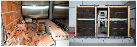
Figure 10.
Model after Phase 3: infill loss and undamaged exoskeleton.
Additionally, Figure 11 presents the time history comparison between the input acceleration at the shaking table (black line) and the output acceleration recorded by ACC11 (red line) during Test 65 (random excitation, 4–12 Hz, 0.3 g). The peak acceleration at ACC11 (2.455 g) was slightly more than twice the input (1.002 g). ACC11 was positioned at the same location as in the previous phases, at the top corner of the model. The lower amplification in Phase 3, compared to the previous model, confirms the benefits of having the exoskeleton system in place from the beginning, ensuring improved seismic performance and reduced damage. Despite the high excitation level and partial collapse of the infill walls, the exoskeleton remained undamaged and preserved the overall stability of the model.
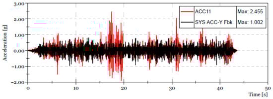
Figure 11.
Time history comparison of input and output accelerations during Test 65.
A comparison of the peak acceleration ratios across the three phases shows that both the damaged configuration (Phase 1) and the repaired frame (Phase 2) exhibited strong dynamic amplification, with the top-floor accelerations reaching roughly three times the input motion. In contrast, the retrofitted configuration (Phase 3) showed a noticeably lower amplification level, remaining below a factor of 2.5. This reduction is consistent with the significantly improved dynamic stability provided by the exoskeleton system and the more controlled deformation pattern observed during the tests.
4.4. Frequency Degradation
The natural frequency was monitored throughout the testing programme to quantify changes in the global dynamic properties of the structure. Figure 12 presents the frequency values obtained in each phase. In all cases, the first point (“Initial”) corresponds to the frequency measured before the start of seismic excitation, while the subsequent points represent the frequencies recorded after each input level.
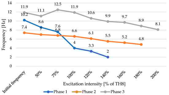
Figure 12.
Natural frequency variation across the three phases.
In Phase 1, the frequency shows a continuous reduction as the input intensity increases, consistent with the progressive loss of stiffness in the RC members and the cracking and loosening of the infill walls. In Phase 2, after the repair, the frequency decreases at a slower rate, indicating a more stable stiffness profile under increasing excitation. In Phase 3, the configuration with the exoskeleton exhibits the highest initial frequency and maintains higher values across all input levels, reflecting the increased lateral stiffness and structural stability provided by the exoskeleton system.
4.5. Interstory Drift Response
Figure 13 presents the interstory drift ratios for the three testing phases. The highest drift demand was observed in Phase 1, reaching approximately 2.5% at 140% of TH8. In Phase 2, the maximum drift was significantly reduced to about 0.8% at 180% of TH8, reflecting the increased stiffness after the rebuilding of the ground-floor infill walls and the addition of the exoskeleton. Phase 3 exhibited the lowest drift values, with a maximum of only 0.5% at 200% of TH8, confirming the superior deformation control provided by the exoskeleton when installed prior to any structural degradation.
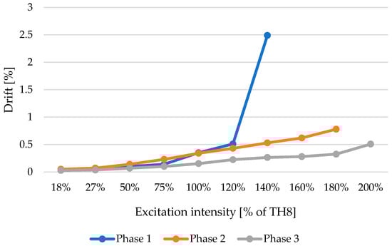
Figure 13.
Interstory drift ratios for the three testing phases.
5. Conclusions
The experimental campaign conducted within the ERIES-RESUME project has demonstrated the structural effectiveness and practical viability of an innovative exoskeleton system composed of laminated timber and aluminium panels for the seismic retrofitting of existing reinforced concrete (RC) buildings.
Key conclusions drawn from the shaking table tests are as follows:
- The exoskeleton system substantially enhanced the seismic behaviour of both tested RC models. In particular, it increased the overall stiffness, reduced interstory drifts, and limited damage to the infill walls.
- The application of the exoskeleton to the previously damaged Model Y effectively restored a large portion of its initial stiffness, as reflected in the recovered dominant frequencies and reduced interstory drifts. This confirms its suitability not only for preventive retrofitting but also for post-damage rehabilitation.
- Throughout all test phases, including increasing seismic intensities up to 200% of the design spectrum, the exoskeleton remained structurally intact, demonstrating its durability and robustness under extreme loading conditions.
- Model X, equipped with the exoskeleton from the beginning, outperformed the retrofitted Model Y in terms of residual stiffness and minimal damage progression, indicating the advantages of early implementation.
- Although the input motions used in the test campaign are limited in number, the excitation levels were selected such that the structure was driven close to its fundamental resonance in all phases. This ensured that the models were tested under highly demanding dynamic conditions, where the structural response is governed primarily by the system’s stiffness, mass distribution, and inherent deformation mechanisms. While the results should not be generalised to earthquake scenarios with substantially different spectral characteristics, the resonance-driven response captured in the tests provides a reliable basis for assessing the relative performance of the two models and the effectiveness of the exoskeleton system.
- The system’s modular assembly, along with the inclusion of recycled cork thermal insulation, offers the potential for simplified installation, thermal upgrading, and architectural integration, making it a multifunctional and sustainable retrofitting solution.
- Studies on seismic retrofit of RC buildings show that adding RC shear walls or steel exoskeletons typically produces large increases in global stiffness and drift reductions, while timber-panel solutions can also produce large stiffness gains, but results are more case-sensitive. Reported outcomes in the literature include shear wall/bracing interventions, which increase global capacity and stiffness up to 250% and 160%, respectively, and often achieving marked drift reductions [33,34], and cold-formed steel exoskeletons produce stiffness and capacity gains in the order of 8% and 30%, respectively [19], while CLT panels combined with friction dampers provide lateral stiffness increases between 90 and 165% but smaller effects when infills dominate the stiffness [35]. In comparison, the proposed hybrid timber–aluminium exoskeleton achieved stiffness gains and interstory drift reductions of similar magnitude, lying toward the upper end of the ranges reported for established retrofit systems. These improvements were obtained using a lightweight and modular assembly that introduced minimal additional mass, exhibited no panel damage even under 200% input intensity, and provided inherent compatibility with façade-level thermal upgrading, thereby offering both structural and functional advantages over more traditional interventions.
The conclusions presented in this work reflect the structural response within the excitation levels achievable by the shake-table facility and do not capture the ultimate capacity of the exoskeleton system. The proposed exoskeleton system presents a promising approach for the integrated seismic and potential thermal upgrading of aging RC buildings, particularly in seismic-prone areas. Future research may focus on long-term performance, life-cycle assessment, cost–benefit analyses, and full-scale applications in real building contexts.
Author Contributions
Conceptualization, M.D., A.B., J.B., Z.R., V.S., A.F. and G.C.M.; methodology, M.D., A.B., J.B., Z.R., V.S., A.F. and G.C.M.; software, V.V., R.C., D.I., T.K., F.M., A.P., E.M. and A.S.; validation, M.D., A.B., J.B., Z.R., V.S. and A.F.; formal analysis, V.V., R.C., D.I., T.K., F.M., A.P., E.M. and A.S.; investigation, V.V., R.C., D.I., T.K., F.M., A.P., E.M. and A.S.; resources, M.D., A.B., J.B., Z.R., V.S. and A.F.; data curation, V.V., R.C., D.I., T.K., F.M., A.P., E.M. and A.S.; writing—original draft preparation, E.M. and A.S.; writing—review and editing, A.F., A.B. and M.D.; visualization, M.D., A.B., J.B., Z.R., V.S. and A.F.; supervision, M.D., A.B., J.B., Z.R., V.S. and A.F.; project administration, M.D., A.B., J.B., Z.R., V.S. and A.F.; funding acquisition, M.D., A.B., J.B., Z.R., V.S. and A.F. All authors have read and agreed to the published version of the manuscript.
Funding
This research was funded by the European Union’s Horizon Europe Framework Programme under Grant Agreement No. 101058684.
Data Availability Statement
Data derived from the current study can be provided to the readers upon their explicit request.
Acknowledgments
This work is part of the transnational access project “ERIES-RESUME”, supported by the Engineering Research Infrastructures for European Synergies (ERIES) project (www.eries.eu). This is ERIES publication number J18.
Conflicts of Interest
The authors declare no conflicts of interest.
References
- Takagi, J.; Wada, A. Recent earthquakes and the need for a new philosophy for earthquake-resistant design. Soil Dyn. Earthq. Eng. 2019, 119, 499–507. [Google Scholar] [CrossRef]
- Di Bucci, D.; Dolce, M.; Bournas, D.A.; Combescure, D.; De Gregorio, D.; Galbusera, L.; Leone, M.; Papa, F.; Sargolini, M.; Theocharidou, M.; et al. Science for Disaster Risk Management 2020: Acting Today, Protecting Tomorrow (EUR 30183 EN); Publications Office of the European Union: Luxembourg, 2021; ISBN 978-92-76-18182-8. [Google Scholar]
- Sheshov, V.; Apostolska, R.; Bozinovski, Z.; Vitanova, M.; Stojanoski, B.; Edip, K.; Bogdanovic, A.; Salic, R.; Jekic, G.; Zafirov, T.; et al. Reconnaissance analysis on buildings damaged during Durres Earthquake Mw6.4, 26 November 2019, Albania: Effects to non-structural elements. Bull. Earthq. Eng. 2021, 20, 795–817. [Google Scholar] [CrossRef]
- United Nations Environment Programme. Global Status Report for Buildings and Construction: Towards a Zero-Emission, Efficient and Resilient Buildings and Construction Sector; UNEP: Nairobi, Kenya, 2020. [Google Scholar]
- European Commission. The European Green Deal—Communication from the Commission to the European Parliament, the European Council, the Council, the European Economic and Social Committee and the Committee of the Regions; European Commission: Brussels, Belgium, 2020. [Google Scholar]
- Huo, T.; Cai, W.; Ren, H.; Feng, W.; Zhu, M.; Lang, N.; Gao, J. China’s building stock estimation and energy intensity analysis. J. Clean. Prod. 2019, 207, 801–813. [Google Scholar] [CrossRef]
- International Energy Agency (IEA). IEA Policy Database. 2021. Available online: https://www.iea.org/policies (accessed on 25 October 2024).
- The White House. FACT SHEET: Biden Administration Accelerates Efforts to Create Jobs Making American Buildings More Affordable, Cleaner, and Resilient. 2021. Available online: https://www.whitehouse.gov (accessed on 25 October 2024).
- Secretary of State. The Energy Efficiency (Building Renovation and Reporting) (Amendment) Regulations 2020. Available online: https://www.legislation.gov.uk/uksi/2020/563/contents/made (accessed on 25 October 2024).
- Pertile, V.; Stella, A.; De Stefani, L.; Scotta, R. Seismic and Energy Integrated Retrofitting of Existing Buildings with an Innovative ICF-Based System: Design Principles and Case Studies. Sustainability 2021, 13, 9363. [Google Scholar] [CrossRef]
- Bournas, D.A. Concurrent Seismic and Energy Retrofitting of RC and Masonry Building Envelopes Using Inorganic Textile-Based Composites Combined with Insulation Materials: A New Concept. Compos. Part B Eng. 2018, 148, 166–179. [Google Scholar] [CrossRef]
- Gkournelos, P.D.; Triantafillou, T.C.; Bournas, D.A. Combined seismic and energy upgrading of existing reinforced concrete buildings using TRM jacketing and thermal insulation. Earthq. Struct. 2019, 16, 625–639. [Google Scholar]
- Kallioras, S.; Bournas, D.A.; Koutas, L.; Molina, F.J. Integrated seismic and energy retrofitting of masonry-infilled RC buildings with textile-reinforced mortar and thermal insulation: Full-scale tests on a five-story prototype. J. Build. Eng. 2024, 98, 111006. [Google Scholar] [CrossRef]
- Margani, G.; Evola, G.; Tardo, C.; Marino, E.M. Energy, Seismic, and Architectural Renovation of RC Framed Buildings with Prefabricated Timber Panels. Sustainability 2020, 12, 4845. [Google Scholar] [CrossRef]
- Badini, L.; Ott, S.; Aondio, P.; Winter, S. Seismic strengthening of existing RC buildings with external cross-laminated timber (CLT) walls hosting an integrated energetic and architectural renovation. Bull. Earthq. Eng. 2022, 20, 5963–6006. [Google Scholar] [CrossRef]
- Callegaro, N.; Albatici, R. Energy retrofit with prefabricated timber-based façade modules: Pre- and post-comparison between two identical buildings. J. Facade Des. Eng. 2023, 11, 001–018. [Google Scholar] [CrossRef]
- Ecosism. Available online: https://www.ecosism.com/moduli/geniale/ (accessed on 25 October 2024).
- Betonwood. Available online: https://www.betonwood.com/ (accessed on 25 October 2024).
- Meglio, E.; Formisano, A. Seismic Design and Analysis of a Cold-Formed Steel Exoskeleton for the Retrofit of an RC Multi-Story Residential Building. Appl. Sci. 2024, 14, 8674. [Google Scholar] [CrossRef]
- Cucuzza, R.; Aloisio, A.; Domaneschi, M.; Nascimbene, R. Multimodal seismic assessment of infrastructures retrofitted with exoskeletons: Insights from the Foggia Airport case study. Bull. Earthq. Eng. 2024, 22, 3323–3351. [Google Scholar] [CrossRef]
- Olivo, J.; Cucuzza, R.; Bertagnoli, G.; Domaneschi, M. Optimal Design of Steel Exoskeleton for the Retrofitting of RC Buildings via Genetic Algorithm. Comput. Struct. 2024, 299, 107396. [Google Scholar] [CrossRef]
- Labò, S.; Passoni, C.; Marini, A.; Belleri, A. Design of diagrid exoskeletons for the retrofit of existing RC buildings. Eng. Struct. 2020, 220, 110899. [Google Scholar] [CrossRef]
- Ferraioli, M.; Lavino, A.; De Matteis, G. A design method for seismic retrofit of reinforced concrete frame buildings using aluminum shear panels. Arch. Civ. Mech. Eng. 2023, 23, 106. [Google Scholar] [CrossRef]
- De Matteis, G.; Ferraioli, M. Metal Shear Panels for Seismic Upgrading of RC Buildings: A Case Study. Key Eng. Mater. 2018, 763, 1058–1066. [Google Scholar] [CrossRef]
- Formisano, A.; Bodganovic, A.; Shoklarovski, A.; Domaneschi, M.; Meglio, E.; Bojadjieva, J.; Rakicevic, Z.; Vlatko, S.; Manojlovski, F.; Poposka, A.; et al. The ERIES_RESUME project: Results of experimental activities. In Proceedings of the 4th International Conference of Steel and Composite for Engineering Structures, Piacenza, Italy, 9–12 July 2025. [Google Scholar]
- MKC EN 15630-1; Steel for the Reinforcement and Prestressing of Concrete—Test Methods—Part 1: Reinforcing Bars, Wire Rod and Wire. ISRM: Skopje, North Macedonia, 2019.
- MKC CA4.002; Concrete—Complementary Rules for MKC EN 206. ISRM: Skopje, North Macedonia, 2015.
- MKC EN 771-1; Specification for Masonry Units—Part 1: Clay Masonry Units. ISRM: Skopje, North Macedonia, 2011.
- MKC EN 772-1; Methods of Test for Masonry Units—Part 1: Determination of Compressive Strength. ISRM: Skopje, North Macedonia, 2011.
- MKC 13412; Standard Methods for the Testing of Mechanical Properties of Building Materials (National Standard). ISRM: Skopje, North Macedonia, 2006.
- MKC EN 12390-3; Testing Hardened Concrete—Part 3: Compressive strength of Test Specimens. ISRM: Skopje, North Macedonia, 2019.
- MKC EN 12390-13; Testing hardened concrete—Part 13: Determination of Secant Modulus of Elasticity in Compression. ISRM: Skopje, North Macedonia, 2021.
- European Commission. Joint Research Centre, Seismic strengthening of RC Buildings: State of the Art and Comparative Assessment; JRC Technical Report; Publications Office of the European Union: Luxembourg, 2016. [Google Scholar]
- Liu, F.; Wang, L.; Lu, X. Experimental investigations of seismic performance of unretrofitted and retrofitted RC frames. In Proceedings of the 15th World Conference of Earthquake Engineering, Lisbon, Portugal, 24–28 September 2012. [Google Scholar]
- Barbagallo, F.; Margani, G.; Marino, E.M.; Moretti, A.; Tardo, C. Impact of retrofit of RC frames by CLT panels and friction dampers. In Proceedings of the 8th ECCOMAS Thematic Conference on Computationsl Methods in Structural Dynamics and Earthquake Engineering, Athens, Greece, 28–30 June 2021. [Google Scholar]


Disclaimer/Publisher’s Note: The statements, opinions and data contained in all publications are solely those of the individual author(s) and contributor(s) and not of MDPI and/or the editor(s). MDPI and/or the editor(s) disclaim responsibility for any injury to people or property resulting from any ideas, methods, instructions or products referred to in the content. |
© 2025 by the authors. Licensee MDPI, Basel, Switzerland. This article is an open access article distributed under the terms and conditions of the Creative Commons Attribution (CC BY) license.