Abstract
This paper explores the static and cyclic behaviours exhibited by X-joints fabricated from circular hollow sections (CHS) incorporating curved chords under bending loading. First, a finite element (FE) model of CHS X-joints was established, and the accuracy was validated by the test results. Then, the influence of the geometric parameters on the ultimate capacity of these joints was deeply conducted through variable parameter expansion analysis, including the chord curvature (R)-to-diameter (D) ratio α, brace diameter (d)-to-chord diameter (D) ratio β, and chord diameter (D)-to-double thickness (2T) ratio γ. In addition, the formulae for the in-plane bending bearing capacity of CHS X-joints with curved chords were examined based on the FE results and typical design guides. Finally, the hysteresis performance of the joints was investigated to modify such formulae. The results show that (1) the bending bearing capacity decreases with increasing α when 3 ≤ α ≤ 12 and changes slightly when α > 12. The bending bearing capacity increases with increasing β and decreases with increasing γ. (2) The bending bearing capacity design formula is modified by FEM results on the basis of the formula derived from Eurocode 3. The API-WSD and LRFD design codes do not consider the effect of γ, and the AIJ seems to be overly conservative. (3) In light of the hysteresis analysis, the smaller the magnitude of γ and the larger that of β, the more favourable the bending load-bearing capacity, ductility coefficient and plastic deformation capability of the joints are found to be. The bending bearing capacity under cyclic loading was close to the value under static loading when α ≥ 9, whereas a reduction coefficient of 0.9 was considered when α < 9. Comparison analyses indicated that the adjusted design formula was suitable for engineering design.
1. Introduction
Circular hollow section (CHS) steel tubes are widely used in reticulated shell structures, large span roof structures and offshore platform structures because of their advantages, such as a beautiful appearance, uniform bending strength without strong and weak axes, high cross-sectional closed torsional rigidity and good antifatigue performance [1]. The joints, which are welding braces to the continuous chord, have become popular joints for stadiums, airport terminals, and other major structures. The mechanical behaviour of joints is critical to a structure’s overall stability, making their study paramount [2].
Research has been carried out to study the mechanical properties of CHS steel tubular joints. Qian et al. [3] undertook a finite element study regarding the static strength of moment-loaded thick-walled CHS X-joints, analysed how the geometric parameters of the joints and the tensile stress of the chord affect the ultimate strength of the joints, and proposed a new function for chord stress. Zhu et al. [4] executed axial compression tests on CHS steel tubular X-joints with external annular stiffening rings and analysed the differences in failure modes and load–displacement curves between unreinforced specimens and reinforced counterparts. It was observed that the bearing capacity of the joints fitted with stiffening rings improved remarkably. Chen et al. [5] executed fire resistance tests on CHS steel T-joints subjected to axial compression and reinforced with internal stiffening rings. It was found that internal ring stiffening effectively boosted the fire resistance of these T-joints, and how the geometrical parameters β and γ affect the joints’ fire resistance was analysed using numerical models. Choo et al. [6] proposed CHS steel tubular X joints with collar plate reinforcement and analysed and compared the load transfer mechanism and failure mode of these reinforced joints. On the basis of the numerical results, the static strength equation was proposed. Kurobane et al. [7] undertook an experimental study on tubular K joints to explore the local buckling behaviour exhibited by the braces. The results revealed that the local buckling of the braces was related not only to the wall thickness of the braces but also to the stiffness properties of the joints. Lee et al. [8] undertook a numerical study focusing on CHS steel tubular KK joints, analysed how weld shape, boundary conditions, loading mode, tube length, and material properties affect the bearing capacity, and proved the numerical model’s validity by means of comparison with experimental results. Tong et al. [9] performed fatigue tests focusing on CHS-CFSHS T-joints. Compared to hollow CHS-SHS T-joint connectors, CHS-CFSHS T-joints were found to possess enhanced fatigue properties, and novel Srhs-N fatigue design curves for CHS-CFSHS and CHS-CFCHS T-joints were developed. Young et al. [10] conducted a numerical study on the static bearing capacity of high-strength steels that failed by chord face plastication, and an average strength calculation formula based on the design formulae was proposed. Yin et al. [11] experimentally investigated the hysteretic behaviour of tubular N joints under quasi-static cyclic loading. Their study of four specimens included an analysis of failure modes and hysteresis loops, along with a comparative evaluation of key performance metrics: the ductility coefficient, energy dissipation capacity, and ultimate strength. Wang et al. [12] experimentally investigated CHS T-joints under cyclic axial compression and in-plane bending to study their failure modes and energy dissipation. The results showed that energy was dissipated through plastic deformation of the chord wall under axial compression and through plastic deformation of the brace under bending. Chen et al. [13] demonstrated that the failure modes of thick-walled CHS X-joints under out-of-plane bending are primarily governed by the brace-to-chord diameter ratio (β) and the chord diameter-to-wall thickness ratio (γ). Zhang et al. [14] identified the structural performance of high-strength steel (HSS) tubular joints as a prerequisite for the safe and economical use of HSS structures. Their results further showed that increasing the welding heat input reduces both the deformation capacity and static strength of S960 joints, an effect that was less pronounced in S690 steels. Xu et al. [15] conducted and presented a systematic experimental investigation focusing on the compressive performance of high-strength steel (HSS) transverse plate-to-CHS X-joints. Pandey et al. [16] conducted a numerical investigation on the postfire structural performance of CFHSS T- and X-joints with CHS braces and SHS/RHS chords. Pandey et al. [17] critically evaluated existing design provisions by validating FE models experimentally and performing a parametric study with an expanded range of geometric variables. They found the European code and CIDECT guidelines to be inadequate and inefficient, leading them to propose a superior set of design guidelines that are user-friendly, cost-effective, and reliable. Nassiraei et al. [18] utilised 263 finite element models to investigate stress concentration factors (SCFs) in tubular T/Y connections strengthened with FRP under out-of-plane bending. Their results demonstrated that FRP reinforcement could reduce the SCF to as low as 29% of that in unreinforced joints, culminating in the proposal of a new design equation. Lyu et al. [19] systematically assessed the axial load-carrying capacity of CHS X-joints retrofitted with externally applied in-plane stiffeners through experimentally validated finite element models and comprehensive parametric analyses. Their findings revealed that these stiffeners augment joint resistance by functioning as equivalent diagonal braces, thereby redistributing stresses and enhancing overall structural integrity. Ding et al. [20] experimentally and numerically investigated the use of external stiffeners to enhance the axial tensile capacity of CHS X-joints. Lyu et al. [21] validated 976 parametric simulations to propose a mechanical model that considers geometric properties, service load, and welding. It was found that external stiffeners increased the stiffness and strength, cover plates increased the effect by avoiding local ovalisation, and welding reduced the ultimate resistance by up to 10%. Chen et al. [22] conducted experiments and numerical analyses on an innovative stiffened CHS X-joint, determined its strength via relevant parameters, and showed that it provides up to 811% strength enhancement over traditional unstiffened joints, proving that the stiffening method is highly effective. Chen et al. [23] conducted experiments and numerical analyses on CHS X-joints stiffened with external ring stiffeners and gusset plates under various chord loads, reported negligible loading path differences, explained tension-induced strength reduction, and proposed a chord stress function with a lower-bound multiplier for conservative design. At present, for CHS steel tubular joints, most research has focused on straight tubules.
A new CHS steel tubular joint with a curved chord was proposed for engineering structures. To obtain better mechanical properties, Chen et al. [24] and Ran et al. [25] analysed CHS steel tubular joints with curved chords. Experimental tests revealed that the ultimate bearing capacity of a joint increases with increasing curvature within a certain curvature range. However, there has not been enough research on this type of joint, and there is no design method or calculation formula for this joint to guide engineering design. Most of these studies focus on performance under static loads. Moreover, to the authors’ knowledge, no other relevant reports have been found, as most research has concentrated more on curved dampers. For example, Fageeri et al. [26] presented an experimental investigation into a novel energy dissipation damper. The proposed device is fabricated from a curved steel plate, which is welded to end flanges and incorporates reinforcing elements to form subpanels. Jiang et al. [27] introduced a novel planar circular C-shaped variable-section device (CCVSD) for seismic control of HSRTBS. A multi-method investigation—entailing theoretical model establishment, experimental cyclic tests, and numerical parametric studies—was conducted. The study validated the model and reported that the CCVSD effectively dissipated energy without buckling, achieving a 76.2% reduction in bearing deformation for the CCVSD-32 configuration.
This paper centres on the static performance and hysteresis performance of CHS X-joints featuring curved chords when subjected to in-plane bending loads. The finite element method was used to establish an X-joint numerical model, and the accuracy was validated by test results [14]. A study on the influence of the geometric parameters on the ultimate capacity of the joints was subsequently conducted. The bending bearing capacity design formula for CHS X-joints with curved chords is analysed based on the FE results and typical design guides. The hysteresis performance is investigated to modify such a formula and provide references for engineering design.
2. Finite Element Model
A finite element (FE) analysis was performed using ANSYS 15.0 to simulate the behaviour of X-joints with curved chords. The numerical model was validated against axial compression test data from Chen et al. [24]. Axial compression tests were conducted on two different cross-sections of CHS X-joints with curved chord. The chord members were processed by hot-rolling and bending into three curvatures with radii (R) of 420 mm, 840 mm, and 1260 mm, respectively. Table 1 summarises the geometric parameters of the specimens, including the curved chord diameter (D), chord wall thickness (T), brace diameter (d), brace wall thickness (t), radius of curvature (R), and the angle between the brace and chord (90°). Key dimensionless geometric ratios are also provided: α = R/D, β = d/D, γ = D/(2T), and τ = t/T. Additional geometric details can be found in Ref. [24]. The finite element mesh used in the simulation is illustrated in Figure 1.

Table 1.
Parameters of the tested CHS X-joints [24].
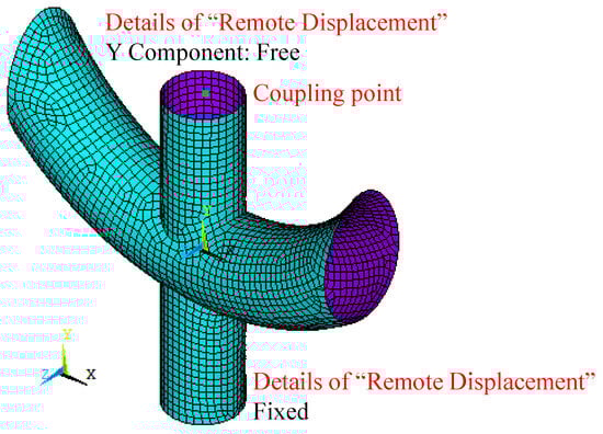
Figure 1.
FE model of curving chord CHS X-joints.
2.1. Material Properties
In order to simulate the hysteresis behaviour of a synchronised, double-stage, yield buckling-restrained brace, Azizi et al. [28] introduced the von Mises yield criterion in the material definition. A combined isotropic and kinematic hardening model was then selected as the reinforcement criterion. The yield and ultimate strengths of the steel were determined from axial compression tests performed by Chen et al. [24]; however, detailed tensile test data were not provided. A simplified bilinear stress–strain relationship was adopted in accordance with the Chinese Code for Metallic Materials (GB/T 228-2002) [29], with an elastic modulus of 2.05 × 10⁵ MPa, a post-yield tangent modulus of 400 MPa, and a Poisson’s ratio of 0.3. The material behaviour was modelled using the von Mises yield criterion and isotropic strain-hardening rules [4,5,8,9,10].
2.2. Element Type and Meshing
Based on numerical simulations by Young et al. [10], both element type (shell or solid) and weld representation had a negligible influence on the bearing capacity of X-joints. Accordingly, a shell-element (SHELL181, 4-node element with six degrees of freedom at each node) model without explicit welds was employed in this study. A mesh convergence study was conducted using joint X4 from Chen et al. [24] with four different mesh sizes. As summarised in Figure 2 and Table 2, a mesh size of 20 mm was found to be suitable and was therefore adopted for the finite element model.
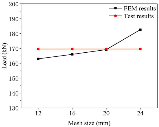
Figure 2.
Mesh sensitivity analysis.
Table 2.
Comparison of mesh sizes.
2.3. Boundary Conditions and Loading Mode
Based on the experimental setup by Chen [24], the boundary conditions were defined as follows: the bottom of the brace was fixed, both ends of the curved chord were left free, and the top of the brace was permitted to displace vertically while constrained in the other two directions. The boundary conditions applied in the FE model were defined as follows: the bottom of the brace was fully fixed, while the top of the brace was restrained in the UX and UZ directions. The Y directions of all nodes on the top loading surface were coupled to the coupling point. A vertical load was applied at the coupling point to represent a uniformly distributed load across the loading surface, as shown in Figure 1. The large displacement static option was selected, and numerical data were recorded for 20 sub-steps.
2.4. Comparative Results
Figure 3 shows the final failure mode of FE models, which were compared with the experimental results. The failure mode of FE (limited to space, take X2 and X4 as examples) consists of the curved chord buckling, with the local plastic deformation, and the intersect zone bulging outward at the curved chord with brace. Finally, the capacity gradually degraded under a large deformation development. The failure mode was consistent with the results obtained using the Chen test [24].
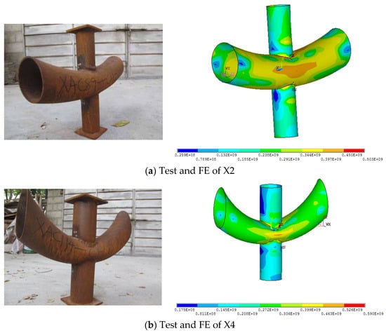
Figure 3.
Failure mode of the test and FE.
Figure 4 is a comparison of the FE and test results for the load–displacement (P-Δ) curves. With the increase in the curvature radius of the chord member, the ultimate strength of the specimen decreases gradually. The P-Δ curves obtained via FE were similar to the test results. A finite element analysis effectively captures the progressive deterioration of bearing capacity under large deformation conditions. The initial stiffness of the FE was greater than that measured in the tests. This occurred because there were more or fewer gaps in the test process, and the deformation of the test compaction effect was included under axial pressure.
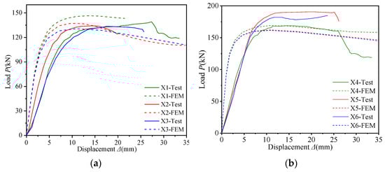
Figure 4.
Comparison of the load–displacement curves of the samples [24]: (a) X1, 2, 3. (b) X4, 5, 6.
Table 3 compares the axial load-bearing capacities from the finite element models. The maximum error was 15.2% for the comparison of the compressive bearing capacities of the FE and test samples. The cause of the error may be the initial eccentricity of the test machine before loading, the steel tubular processing thickness not being uniform, and/or the residual stress being generated during joint welding. In general, the FE model has high analytical accuracy and can be used for subsequent research.
Table 3.
Comparison of the ultimate loading capacity.
3. Static Bending Bearing Capacity
A schematic of the curved-chord CHS X-joints geometry is provided in Figure 5. The geometric parameters of the joint include the curved chord diameter (D), wall thickness (T), brace diameter (d), brace wall thickness (t), radius of curvature (R), vertical distance from the brace top to the joint centre (H), and horizontal distance from the chord ends to the joint centre (L). The angle between the brace and chord member was 90°. The boundary conditions were defined as follows: the brace bottom was fully fixed, the brace top was restrained in the UZ direction, both ends of the curved chord were constrained in UY and UZ, and all nodes on the top loading surface were coupled in the X-direction to a reference point. A horizontal load was imposed at the coupling point to represent the uniformly distributed load acting on the loading surface.
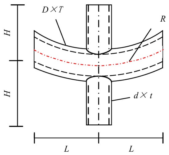
Figure 5.
Geometric model of curving chord CHS X-joints.
The specimens were designed for parametric analysis according to Table 4, which includes the following dimensionless geometric ratios: α = R/D, β = d/D, γ = D/(2T), and τ = t/T. The ranges of the parameters were 3 ≤ α ≤ 100/3, 0.2 ≤ β ≤ 0.8, and 15 ≤ γ ≤ 30. According to previous research [30], the thickness ratio τ (t/T) exhibits negligible influence on the bending capacity of X-joints. To prevent the brace from breaking down after the curved chord, τ = 0.8. To mitigate the risk of global brace buckling, the vertical distance from the brace’s top to the X-joint centre is defined as H = 500 mm; however, this distance cannot capture the dominant collapse mechanism of the X-joints. Additionally, the horizontal distance between the curved chord’s ends and the X-joint centre is set to L = 600 mm, aiming to avoid the curved chord-brace intersection zone being affected by the chord’s end regions.
Table 4.
Parameters of CHS X-joints for FE analyses.
3.1. Parametric Analysis of α
The bending–rotation (Muf-θ) curves of joints with different values of parameter α are shown in Figure 6. The deformation limit was proposed by Yura et al. [31] to characterise the bending resistance of the connection. Notably, the joint-bending bearing capacity was determined by the load at the rotation deformation limit (=80 fy/E) on the Muf-θ curve. This method is recognised by many scholars [32]. Figure 6 shows that the bending bearing capacity decreases with increasing α when α ≤ 12, and the large degree of chord bending leads to additional bending stress in the intersection area at the joint. The results show that local buckling failure of the brace occurred in the CHS X-joints with curved chords, which means the ultimate strengths of CHS X-joints with curved chords are greater than those of traditional CHS X-joints with straight chords. When the specimen α ≤ 12, the mutual restraint effect at the joints is basically the same as that at the straight chord nodes, and the additional stress caused by bending can be ignored. This finding is in agreement with the correlation observed between axial capacity and radius of curvature during testing [24].
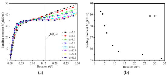
Figure 6.
Effect of α: (a) Curves of Muf-θ. (b) Curves of Muf-α.
3.2. Parametric Analysis of β and γ
Figure 7 presents the bending–rotation (Muf-θ) curves of joints featuring different β and γ parameters. They reported that the bending bearing capacity increases with increasing β and that the bending bearing capacity decreases with increasing γ. A simplified model described by Azizi et al. [28] that intersects the zone-bending moment can be simplified to a pair of forces. When β increases, the brace diameter d increases, the distance of a pair of forces increases, the bending bearing capacity increases, γ increases, the curved chord wall thickness t decreases, the bending stiffness decreases, and the bending bearing capacity decreases.
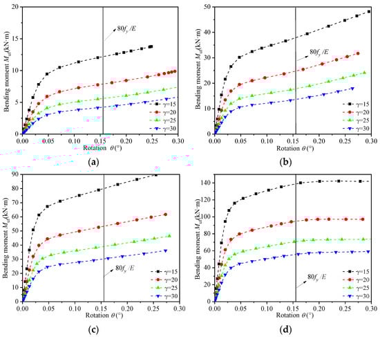
Figure 7.
Curves of Muf-θ: (a) β = 0.2. (b) β = 0.4. (c) β = 0.6. (d) β = 0.8.
3.3. Design Formula
The general forms of the bending bearing capacity of straight chords and straight CHS steel tubular X joints under in-plane bending loads in API-WSD [33], API-LRFD [34], Eurocode 3 [35], and AIJ [36] design guidance are as follows:
where fy refers to the yield stress of the chord member, θ defines the inclination angle between the brace and the chord, and Qu is a geometric coefficient.
Three design rule formulae for the calculation of Qu in Formula (1) are as follows:
- (1)
- API-WSD and LRFD design rule [33,34]:
- (2)
- Eurocode 3 design guide [35]:
- (3)
- AIJ design guide [36]:
The bending bearing capacities of the FEs were compared with three design rules, and the ratios of Muf/Mu1, Muf/Mu2, and Muf/Mu3 are shown in Table 5. They reported that (1) the API-WSD and LRFD design rule [33,34] does not consider the effect of the diameter-to-thickness ratio γ (= D/(2T) on the moment capacity, but the ratio of Muf/Mu1 increases with increasing γ, indicating that the API-WSD and LRFD design rule is not suitable for the calculation of the joints; (2) the Eurocode 3 [35] and AIJ [36] design rules consider the influence of β (=d/D), γ (=D/(2T)) on the bending bearing capacity, and Muf/Mu2, Muf/Mu3 have little effect on the changes in β and γ, except when β = 0.2, because the brace diameter d is so small that the distance of a pair of forces is long when β = 0.2, and the chord experiences local buckling damage. (3) A comparison of the ratio of Muf/Mu2 with the ratio of Muf/Mu3 revealed that the ratio of Muf/Mu3 was greater, indicating that the AIJ design guide was too safe to waste material; therefore, the Eurocode 3 design guide was suitable.
Table 5.
Comparison of FEs with design guides.
According to the above comparison analysis, the bending bearing capacity design formula was established on the basis of the Eurocode 3 design formula and modified via FE analysis. The influence of α (=R/D) was also used for the amendment coefficient δ, which was multiplied by the design formula as follows: δ = α−0.05 when α ≤ 12; δ = 0.88 when α > 12. The adjustment coefficient of 1.08 was multiplied to design a formula to ensure that the steel was fully usable. Finally, the adjusted bending bearing capacity design formula was as follows:
A comparison was made between the FE model’s bending capacity and the modified design formula. The relationships between the ratio of Muf/Mu and the parameters β ( = d/D) and γ ( = D/(2T)) are shown in Figure 8. The ratio of Muf/Mu changes little when β and γ are between 1.02 and 1.17 and is only beyond the range when β = 0.2. These findings indicate that the adjusted design formula is a suitable engineering design reference.
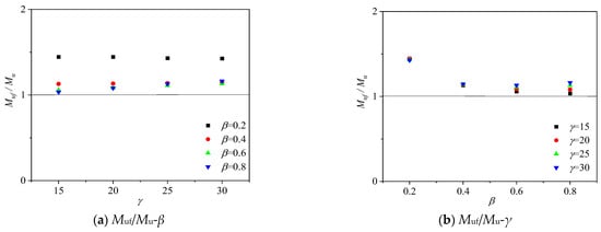
Figure 8.
Curves of Muf/Mu-β and Muf/Mu-γ.
4. Hysteresis Performance of X Joints
Engineering steel tubular joints is generally not in accordance with the principle of the strength or superstrength of the components used to design the structures. The first site of destruction is often found in the joint zone. The Bauschinger effect occurs on steel tubular joints produced by reciprocating loads. Understanding the hysteretic behaviour of X-joints under in-plane bending is critical. This study numerically examines the influence of key geometric parameters—α (=R/D), β (d/D), and γ (=D/2T)—on the hysteretic behaviour of CHS X-joints. The hysteretic behaviour was assessed based on hysteresis loops, skeleton curves, and the ductility coefficient. Some of the samples employed in the study are presented in Table 4. For the sake of result comparability, the same material properties and FE models consistent with those in Section 3 were employed, and the X direction horizontal reciprocating load was applied for a total of 12 cycles, with a displacement of 5 mm for each cycle step and loading path, as shown in Figure 9.
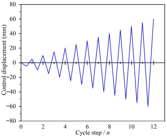
Figure 9.
Loading path.
4.1. Hysteresis Curves of the Joints
As illustrated in Figure 10, the hysteresis loops of all specimens exhibited a spindle-shaped form, indicating favourable plastic deformation capacity in the joints. Figure 10a–e show that the area of the hysteresis curve increases slightly with increasing α (=R/D) and that the energy consumption capacity increases slightly. Figure 10f–i show that the area of the hysteresis curve decreases with increasing γ (=D/(2T)) and that the energy consumption capacity decreases. Figure 10f,j,k,l show that the area of the hysteresis curve increases with increasing β (=d/D) and that the energy consumption capacity increases.
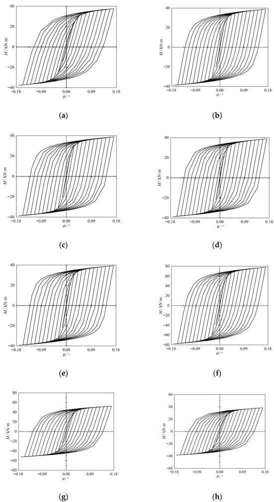
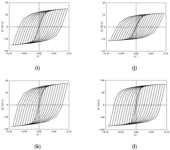
Figure 10.
Hysteresis curves of the samples: (a) XB1. (b) XB5. (c) XB6. (d) XB7. (e) XB8. (f) XB17. (g) XB18. (h) XB19. (i) XB20. (j) XB9. (k) XB13. (l) XB21.
4.2. Skeleton Curves of the Joints
By connecting the peak load points from each cycle, the skeleton curve was obtained. Figure 11 presents the skeleton curves of each specimen. Figure 11a illustrates that the initial stiffness increases slightly with increasing α (=R/D). Figure 11b illustrates that stiffness at the onset of loading decreases with increasing γ (=D/(2T)). Figure 11c shows that the stiffness at the onset of loading increases with increasing β (=d/D). Azizi et al. [28] used the deformation limit to determine the joint-bending bearing capacity under reciprocating loading, which was compared with the static bending bearing capacity in Table 6. It was found that Muf,h/Muf ˃ 1, when α ≥ 9, means that the moment capacity under reciprocating load can be determined using the static moment capacity formula; however, Muf,h/Muf < 1, when α < 9, means the moment capacity under reciprocating load can be determined using the static moment capacity formula to multiply a reduction coefficient of 0.9.
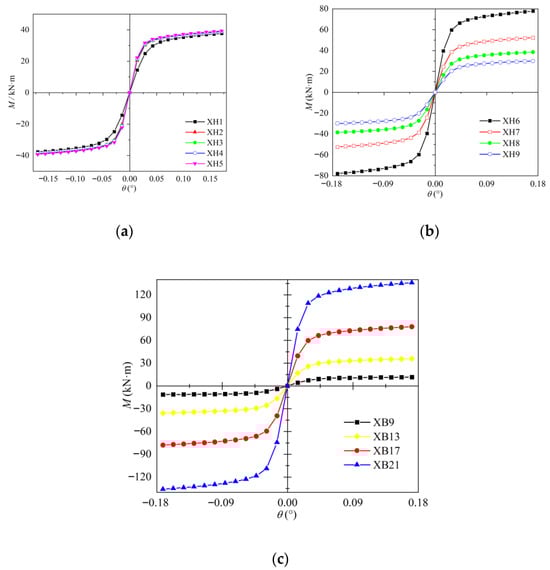
Figure 11.
Skeleton curves of the samples: (a) Comparison of α. (b) Comparison of γ. (c) Comparison of β.
Table 6.
Bending bearing capacity comparison of hysteresis Muf,h, with the static Muf.
4.3. Ductility Coefficient
The ductility coefficient μ serves as a key parameter for evaluating the plastic deformation capacity of joints. The displacement ratio θu/θy at which the joint reached the yield state was used to determine the ductility coefficient μ (i.e., μ = θu/θy). The joint ductility increases with increasing ductility coefficient μ. The method of displacement θy proposed by ECCS [37] is shown in Figure 12.
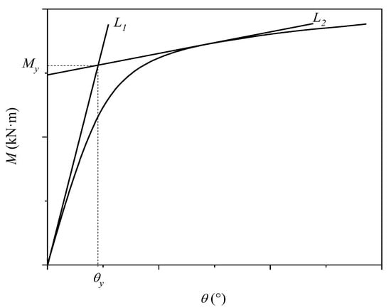
Figure 12.
Determination of the displacement θy.
The yield displacement θy was determined by the intersection of two lines: L1, the initial tangent to the first-cycle hysteresis curve passing through the origin, and L2, a tangent to the skeleton curve with a slope equal to 0.1 times that of L1.
The ductility coefficients for all specimens are presented in Table 7, which reveals that the negative ductility coefficient of the sample was slightly smaller than the positive ductility coefficient. A comparison of the samples XB1, XB5, XB6, XB7, and XB8 revealed that the ductility coefficient and plastic deformation ability increase with increasing α (=R/D); XB17, XB18, XB19, and XB20 revealed that the ductility coefficient and plastic deformation ability decrease with increasing γ (=D/(2T)); and XB9, XB13, XB17, and XB21 revealed that the ductility coefficient and plastic deformation ability increase with increasing β (=d/D).
Table 7.
Ductility coefficients of the samples.
5. Conclusions
A numerical study investigating the static and hysteretic response of curved-chord CHS X-joints subjected to in-plane bending. The accuracy of the FE model was verified by test results [24]. A numerical/parametric study was carried out to examine the effect of geometric parameters on the ultimate capacity of the joints. The bending bearing capacity design formula for curved-chord CHS X-joints is analysed on the basis of the FE results and typical design guides of the API-WSD [33] and API-LRFD [34] design rules and the Eurocode 3 [35] and AIJ [36] design guides. The effect of geometric parameters on the joint hysteretic behaviour is examined. The main findings are summarised below:
- (1)
- The bending bearing capacity of CHS X joints with curved chords decreases with increasing α when 3 ≤ α ≤ 12 and changes little with α when α > 12. An increase in β enhances the flexural resistance, whereas a higher γ value diminishes it.
- (2)
- The bending bearing capacity design formula is modified by FEM results on the basis of the formula derived from Eurocode 3. The API-WSD and LRFD design rule does not consider the effect of γ, and the AIJ seems to be overly conservative.
- (3)
- In the hysteresis analysis, the smaller γ and the larger β are, the better the bending bearing capacity, ductility coefficient, and plastic deformation ability of the joints are. The bending bearing capacity under cyclic loading is close to the value under static loading when α ≥ 9, whereas a reduction coefficient of 0.9 should be considered when α < 9. A comparison analysis indicates that the adjusted design formula is a suitable engineering design reference.
Author Contributions
Conceptualization, J.S., Z.Z. and L.J.; Methodology, C.Z. and L.R.; Software, C.Z.; Validation, C.Z., Z.Z., L.R. and L.Z.; Investigation, C.Z., Z.Z., X.L., L.R. and L.Z.; Resources, Z.Z., L.R. and L.Z.; Writing—original draft, C.Z.; Writing—review & editing, J.S. and X.L.; Visualization, X.L.; Supervision, J.S. and L.J.; Project administration, J.S. and Z.Z.; Funding acquisition, J.S. and L.J. All authors have read and agreed to the published version of the manuscript.
Funding
Open funding from Hubei Key Laboratory of Blasting Engineering, Jianghan University (HKLBEF2020B).
Data Availability Statement
Data will be provided by the corresponding author upon reasonable request.
Conflicts of Interest
Authors Chen Zhou, Zhen Zhao, Lanzhe Rao and Lifeng Zou were employed by the company 3rd Construction Co., Ltd. of China Construction 5th Engineering Bureau. The remaining authors declare that the research was conducted in the absence of any commercial or financial relationships that could be construed as a potential conflict of interest.
References
- Wang, W.; Chen, Y.; Zhao, X. State of the art and key issues on performance-based design of steel tubular joints. China Civ. Eng. J. 2007, 40, 1–7. [Google Scholar]
- Soh, C.K.; Chan, T.K.; Yu, S.K. Limit analysis of ultimate strength of tubular X-joints. J. Struct. Eng. ASCE 2000, 126, 790–797. [Google Scholar] [CrossRef]
- Qian, X.D.; Choo, Y.S.; Liew, J.Y.R.; Wardenier, J. Static strength of thick-walled CHS X-joints subjected to brace moment loadings. J. Struct. Eng. ASCE 2007, 133, 1278–1287. [Google Scholar] [CrossRef]
- Zhu, L.; Yang, K.; Bai, Y.; Sun, H.; Wang, M. Capacity of steel CHS X-joints strengthened with external stiffening rings in compression. Thin-Walled Struct. 2017, 115, 110–118. [Google Scholar] [CrossRef]
- Chen, C.; Shao, Y.B.; Yang, J. Study on fire resistance of circular hollow section (CHS) T-joint stiffened with internal rings. Thin-Walled Struct. 2015, 92, 104–114. [Google Scholar] [CrossRef]
- Choo, Y.S.; Liang, J.X.; Van der Vegte, G.J.; Liew, J.Y.R. Static strength of collar plate reinforced CHS X-joints loaded by in-plane bending. J. Constr. Steel Res. 2004, 60, 1745–1760. [Google Scholar] [CrossRef]
- Kurobane, Y.; Ogawa, K.; Ochi, K.; Makino, Y. Local buckling of braces in tubular K-joints. Thin-Walled Struct. 1986, 4, 23–40. [Google Scholar] [CrossRef]
- Lee, M.M.K.; Wilmshurst, S.R. Numerical modelling of CHS joints with multiplanar double-K configuration. J. Constr. Steel Res. 1995, 32, 281–301. [Google Scholar] [CrossRef]
- Tong, L.W.; Xu, G.W.; Yang, D.L.; Mashiri, F.R.; Zhao, X.L. Fatigue behavior and design of welded tubular T-joints with CHS brace and concrete-filled chord. Thin-Walled Struct. 2017, 120, 180–190. [Google Scholar] [CrossRef]
- Lan, X.; Chan, T.-M.; Young, B. Static strength of high strength steel CHS X-joints under axial compression. J. Constr. Steel Res. 2017, 138, 369–379. [Google Scholar] [CrossRef]
- Yin, Y.; Han, Q.H.; Bai, L.J.; Yang, H.D.; Wang, S.P. Experimental Study on hysteretic behaviour of tubular N-joints. J. Constr. Steel Res. 2009, 65, 326–334. [Google Scholar] [CrossRef]
- Wang, W.; Chen, Y.Y. Hysteretic behaviour of tubular joints under cyclic loading. J. Constr. Steel Res. 2007, 63, 1384–1395. [Google Scholar] [CrossRef]
- Wang, W.; Chen, Y.; Meng, X.; Leon, R.T. Behavior of thick-walled CHS X-joints under cyclic out-of-plane bending. J. Constr. Steel Res. 2010, 66, 826–834. [Google Scholar] [CrossRef]
- Zhang, J.J.; Lan, X. Static performance of S690 and S960 high strength steel CHS X-joints under brace axial tension: An experimental investigation considering welding heat input effects. Thin-Walled Struct. 2025, 216, 113705. [Google Scholar] [CrossRef]
- Xu, X.W.; Lan, X. Experimental study on compressive behavior of S690 and S960 high strength steel transverse plate-to-CHS X-joints considering welding heat input effects. Thin-Walled Struct. 2025, 215, 113510. [Google Scholar] [CrossRef]
- Pandey, M.; Young, B. Cold-formed high strength steel CHS-to-RHS T-and X-joints: Performance and design after fire exposures. Thin-Walled Struct. 2023, 189, 110793. [Google Scholar] [CrossRef]
- Pandey, M.; Young, B. New design rules of cold-formed high strength steel CHS-to-RHS X-joints. Thin-Walled Struct. 2023, 188, 110642. [Google Scholar] [CrossRef]
- Nassiraei, H.; Rezadoost, P. Parametric study and formula for SCFs of FRP-strengthened CHS T/Y-joints under out-of-plane bending load. Ocean Eng. 2021, 221, 108313. [Google Scholar] [CrossRef]
- Lyu, J.; Yan, S.; Zhao, X. Behaviour of CHS X-joints stiffened with external in-plane stiffeners and design equations. J. Constr. Steel Res. 2025, 232, 109645. [Google Scholar] [CrossRef]
- Ding, Y.; Zhu, L.; Zhang, K.; Bai, Y.; Sun, H. CHS X-joints strengthened by external stiffeners under brace axial tension. Eng. Struct. 2018, 171, 445–452. [Google Scholar] [CrossRef]
- Lyu, J.; Yan, S.; Zhao, X.; Chen, X.; Wu, X.; Xu, X.; Gao, F. Behaviour of in-service CHS gap K-joints strengthened with external stiffeners. Thin-Walled Struct. 2024, 200, 111897. [Google Scholar] [CrossRef]
- Chen, Y.; Hu, Z.; Guo, Y.; Wang, J.; Dan, H.; Liu, Q.; Pan, Y. Ultimate bearing capacity of CHS X-joints stiffened with external ring stiffeners and gusset plates subjected to brace compression. Eng. Struct. 2019, 181, 76–88. [Google Scholar] [CrossRef]
- Chen, Y.; Hu, Z.; Guo, Y.; Wang, J.; Tong, G.; Liu, Q.; Pan, Y. Effects of chord preload on strength of CHS X-joints stiffened with external ring stiffeners and gusset plates. Eng. Struct. 2019, 195, 125–143. [Google Scholar] [CrossRef]
- Chen, Y.; Feng, R.; Wang, C.Y. Tests of steel and composite CHS X-joints with curved chord under axial compression. Eng. Struct. 2019, 99, 423–438. [Google Scholar] [CrossRef]
- Feng, R.; Chen, Y.; Chen, T. Flexural behaviour of concrete-filled CHS X-joints with curved chord under out-of-plane bending. Eng. Struct. 2017, 145, 254–272. [Google Scholar] [CrossRef]
- Fageeri, A.; Leblouba, M.; Al-Sadoon, Z.A.; Taklas, M.; Mohamad, F. Experimental investigation on a novel curved steel damper for the beam-column joints of steel structures. Structures 2023, 57, 105300. [Google Scholar] [CrossRef]
- Jiang, L.; Liu, X.; Wang, G.; Hu, Y.; Jiang, L. A buckling-restraint planar circular C-shaped variable section energy dissipation device for seismic response control of high-speed railway track-bridge system. Eng. Struct. 2025, 338, 120577. [Google Scholar] [CrossRef]
- Azizi, H.; Ahmadi, J.; Kazemi, F. Enhancing seismic resilience in steel frames with synchronized double-stage yield buckling-restrained braces. Soil Dyn. Earthq. Eng. 2025, 198, 109587. [Google Scholar] [CrossRef]
- GB/T 228-2002; Chinese Code for Metallic Materials. China Standards Press: Beijing, China, 2002.
- Wang, W.; Chen, Y. Nonrigid behavior and design formulae of steel tubular joints. Ind. Constr. 2005, 35, 5–9. [Google Scholar]
- Yura, J.A.; Zettlemoyer, N.; Edwards, I.F. Ultimate capacity equations for tubular joints. In Proceedings of the Offshore Technology Conference, Houston, TX, USA, 5–8 May 1980; Volume 3690. [Google Scholar]
- Lee, M.M.; Gazzola, F. Design Equation for Offshore Overlap Tubular K-Joints under In-Plane Bending. J. Struct. Eng. ASCE 2006, 132, 1087–1095. [Google Scholar] [CrossRef]
- API RP2A-WSD; Recommended Practices for Planning, Designing and Constructing Fixed Offshore Platforms—Working Stress Design. American Petroleum Institute: Washington, DC, USA, 1993.
- API RP2A-LRFD; Recommended Practice for Planning, Designing and Constructing Fixed Offshore Platforms—Load and Resistance Factor Design. American Petroleum Institute: Washington, DC, USA, 1993.
- DD ENV 1993-1-1; CEN: Eurocode 3: Design of Steel Structures, Part 1-1: General Rules and Rules for Buildings. European Committee for Standardization: London, UK, 1992.
- AIJ. Recommendations for the Design and Fabrication of Tubular Truss Structures in Steel; Architectural Institute of Japan: Tokyo, Japan, 2002. [Google Scholar]
- European Convention for Constructional Steelwork. ECCS Technical Committee 1—Structural Safety and Loadings, Technical Working Group 1.3-Seismic Design, Recommended Testing Procedure for Assessing the Behavior of Structural Steel Elements Under Cyclic Loads, 1st ed.; ECCS: Brussels, Belgium, 1986. [Google Scholar]
Disclaimer/Publisher’s Note: The statements, opinions and data contained in all publications are solely those of the individual author(s) and contributor(s) and not of MDPI and/or the editor(s). MDPI and/or the editor(s) disclaim responsibility for any injury to people or property resulting from any ideas, methods, instructions or products referred to in the content. |
© 2025 by the authors. Licensee MDPI, Basel, Switzerland. This article is an open access article distributed under the terms and conditions of the Creative Commons Attribution (CC BY) license (https://creativecommons.org/licenses/by/4.0/).