Abstract
In submerged tunnel construction, the installation accuracy of pre-embedded components directly impacts subsequent engineering quality and operational safety. However, current on-site construction still primarily relies on manual measurement and two-dimensional drawings for guidance, resulting in significant positioning errors, delayed information transmission, and inefficient installation inspections. To enhance the digitalization and intelligence of submerged tunnel construction, this paper proposes a BIM- and AR-based human–machine collaborative management method for pre-embedded components in submerged tunnel segments. This method establishes a site-wide panoramic model as its foundation, enabling intelligent matching of component model geometry and semantic information. It facilitates human–machine interaction applications such as AR-based visualization for positioning and verification of pre-embedded components, information querying, and progress simulation. Additionally, the system supports collaborative operations across multiple terminal devices, ensuring information consistency and task synchronization among diverse roles. Its application in the Mingzhu Bay Submerged Tunnel Project in Nansha, Guangzhou, validates the feasibility and practical utility of the proposed workflow in a pilot case, and indicates potential for further validation in broader construction settings.
1. Introduction
Submerged tunnel serves as a vital form of water-crossing transportation infrastructure, widely applied in complex environments such as seabeds and riverbeds for transportation construction [1]. Their construction process involves highly complex technology and demands extreme precision, particularly during the prefabrication stage of the tubes. This phase extensively involves the installation of various embedded components, including tube end fittings, openings for electromechanical facilities, and outfitting components [2]. These pre-embedded components are not only diverse in type and complex in structure but also require strict control over their spatial positioning and dimensional parameters. Any deviation may compromise subsequent equipment installation, segment alignment, and waterproofing performance. However, current engineering practices rely primarily on two-dimensional drawings and manual measurements for managing the installation of pre-embedded components in submerged tunnel projects. The absence of a unified visualization platform and intelligent verification methods results in inefficient component positioning, high error risks, and poor information flow efficiency, hindering the precision and digitalization of submerged tunnel construction processes [3].
In recent years, BIM (Building Information Modeling) and AR (Augmented Reality) have garnered significant attention in the engineering construction field. BIM possesses robust geometric modeling and semantic data management capabilities, providing visualization support and data integration services throughout the project lifecycle [4]. AR, by overlaying virtual information onto real-world scenes, enables construction personnel to intuitively comprehend complex structural information and operational procedures [5,6,7]. The integration of these technologies is regarded as a key pathway for advancing smart construction. Nevertheless, existing BIM-AR fusion applications face multiple challenges: First, BIM models are often confined to the preliminary design phase, failing to form a closed-loop with the construction process and thus unable to support dynamic feedback on site conditions. Second, AR systems exhibit low coupling with BIM data, resulting in significant model alignment errors that compromise construction accuracy. Third, inadequate mechanisms for multi-device collaboration and data synchronization limit the practical implementation of AR technology in multi-person, multi-scenario environments.
To address these challenges, this study proposes a human–machine collaborative management method for pre-embedded components in submerged tunnel segments, integrating BIM and AR technologies. Targeting core requirements such as positioning accuracy, information acquisition, and multi-role collaboration for pre-embedded components, it establishes a comprehensive technical framework encompassing 3D scene modeling, scene perception, human–machine interaction operations, and collaborative management. The system employs the Matterport Pro 2 panoramic camera for efficient data capture of prefabricated environments. By integrating BIM models, it constructs geometric and semantic information for components, achieving spatial alignment and data fusion between virtual and physical environments. Building upon this foundation, an AR-based interactive module was developed to support on-site verification of pre-embedded component positioning, information querying, and progress comparison. Concurrently, leveraging spatial anchors and network communication mechanisms, the system enables information sharing and operation synchronization across multiple terminals. The system has been deployed and validated in the Nansha Mingzhu Bay submerged tunnel project in Guangzhou. The results from this pilot case indicate the feasibility of improving component installation accuracy, information acquisition efficiency, and construction visualization within the investigated project context.
The contributions of this work are threefold. Theoretically, it extends human–machine collaboration research to the context of submerged tunnel prefabrication. Methodologically, it develops an integrated BIM-AR framework covering scene modeling, geometric–semantic alignment, AR interaction, and multi-terminal collaboration. Practically, it offers an engineering-validated workflow that improves the accuracy and efficiency of pre-embedded component installation.
The structure of this paper is as follows: Section 2 reviews relevant research; Section 3 introduces the proposed method and implementation details; Section 4 presents the application and experimental results from the Nansha Mingzhu Bay submerged tunnel project; Section 5 summarizes key conclusions and outlines future directions.
2. Literature Review
This section reviews research progress in three areas: the application of BIM in submerged tunnel, the application of AR in construction management, and the integrated application of BIM-AR. This review provides the theoretical and technical foundation for subsequent system design and experimental validation.
2.1. Application of BIM in Submersed Tunnel
As a vital tool for digital construction engineering, BIM has been progressively applied to large-scale infrastructure projects such as tunnels, bridges, and subways [8]. In submerged tunnel construction, BIM can be utilized to construct three-dimensional models of tube section structures and component layouts, enabling the integration and visualization of structural information [9]. Research indicates that BIM technology can effectively enhance collaboration efficiency during the construction design phase, optimize embedded component layout plans, reduce component collisions and pipeline crossings, while providing geometric and semantic data support for the construction process [10,11].
However, current BIM application in submerged tunnel projects remains primarily confined to the design phase, lacking real-time linkage with actual construction sites [12]. Construction personnel cannot directly obtain component location, dimensions, and status information through BIM models, forcing on-site operations to rely on two-dimensional drawings and experience-based judgments, thereby impacting construction efficiency and precision. Furthermore, the data update mechanism for BIM models during the construction phase remains imperfect, struggling to meet the demands of dynamic on-site adjustments and progress management.
2.2. Application of AR in Construction Management
AR, with its ability to fuse virtual and real elements, offers novel approaches to visualization management and human–machine interaction at construction sites [13]. By overlaying virtual models onto real environments, construction personnel can visually inspect spatial relationships, installation positions, and construction sequences of structural components in real time, thereby reducing information transmission errors and enhancing operational intuitiveness [14,15]. Existing research has successfully applied AR technology to scenarios such as rebar positioning, pipeline installation, and concrete pouring, yielding positive outcomes.
Regarding interaction methods, AR technology supports multiple natural interaction modes including touch, voice, gestures, and eye tracking, making it particularly suitable for construction environments where hands are restricted and operations are complex. Concurrently, advancements in head-mounted devices and mobile terminals have continuously optimized AR systems in positioning accuracy, rendering quality, and user experience, paving the way for their implementation in construction engineering [16,17].
Nevertheless, existing AR systems generally suffer from weak real-space perception capabilities, significant model alignment errors, and isolated component information. They lack deep integration with construction semantic data and have yet to establish efficient, systematic human–machine collaborative workflows.
2.3. Integrated Application of BIM-AR
The integration of BIM and AR is widely recognized as a key pathway for advancing smart construction and digitalization at construction sites. BIM models possess rich component-level geometric and semantic information, providing data support throughout the entire construction process. AR, meanwhile, enables real-time overlay of virtual models onto actual scenes, enhancing construction personnel’s intuitive understanding of component spatial positioning, installation relationships, and status information. Existing research indicates that BIM-AR plays a vital role in construction planning, installation guidance, quality inspection, and operations management [18,19]. Tan et al. [20] proposed a framework integrating computer vision, AR, and BIM to enhance the efficiency of building defect detection and data management. Chen et al. [18] enhanced building fire safety and rescue efficiency by integrating BIM, IoT, and AR/VR systems. Chalhoub et al. [21] demonstrated that AR methods significantly reduced worker errors and rework compared to traditional 2D drawings during electrical conduit construction. Such research effectively expands the on-site application boundaries of BIM models, enhancing the visualization and interactivity of construction management.
To achieve high-precision alignment of pre-embedded components in submerged tunnels, the integration of BIM and AR faces challenges not encountered in other AR applications such as defect detection or electrical installations. High-density steel and potential obstructions complicate the accurate alignment of BIM models with real-world environments, requiring robust tracking systems. Additionally, integrating BIM’s semantic data into AR workflows remains difficult, affecting the timely perception and verification of component attributes. Current systems primarily focus on single-device usage and lack support for seamless information synchronization across multiple devices and roles. These issues underscore the need for the proposed BIM–AR integration framework, which addresses accuracy, tracking stability, and scalability in real-world construction environments.
3. Methodology
To achieve visual positioning and inspection of pre-embedded components in submerged tunnel, real-time human–machine interaction, and collaborative management, this paper designs and develops a BIM- and AR-based human–machine collaborative management system for inspecting pre-embedded components in submerged tubes. The system encompasses the complete technical workflow from intelligent acquisition of submerged tunnel prefabrication scenarios, accurate matching of model geometry and semantic information, AR human–machine interaction application development, to AR human–machine collaborative management of multiple terminal devices. The overall system architecture is shown in Figure 1.
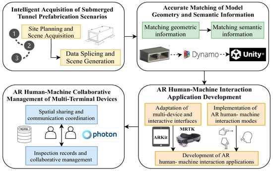
Figure 1.
System architecture diagram.
3.1. Intelligent Acquisition of Submerged Tunnel Prefabrication Scenarios
The high-precision installation and inspection of pre-embedded components for submerged tunnel rely on the completeness and spatial accuracy of on-site construction data. To support subsequent spatial alignment between the submerged tunnel BIM model and the precast construction site, this paper designs an intelligent data acquisition workflow centered on BIM-assisted planning, Matterport Pro 2 panoramic scanning, feature marker placement, and data stitching processing. This approach systematically achieves digital modeling of the submerged tunnel precast construction site.
3.1.1. Site Planning and Scene Acquisition
In the field data collection for prefabricated submerged tunnel construction, precise spatial information serves as the fundamental guarantee for subsequent efficient alignment between BIM and AR. To this end, this study developed a systematic data collection plan based on BIM model-assisted planning and design. Leveraging the high-efficiency data capture capabilities of the Matterport Pro 2 panoramic camera, this study reconstructed an image-based 3D panoramic model of the prefabrication scene from multiple panoramic scans, which serves as an as-built spatial reference for subsequent BIM alignment and AR visualization.
First, a comprehensive submerged tunnel BIM model was constructed in Revit, incorporating all pre-embedded components—including MEP embedments, end embedments, and top outfitting components. Each component within the BIM model was assigned a unique Component ID along with complete geometric dimensions, installation locations, and elevation data.
To efficiently extract scan target and candidate area information, two new IFC attributes were added to the submerged tunnel BIM model: “IfcScanTarget” and “IfcCandidateArea”. These new IFC attributes must be added as instance attributes to each component. For scan targets such as formwork, concrete models, and prefabricated components, set the “IfcScanTarget” attribute to “true.” For candidate areas, set the “IfcCandidateArea” attribute to “true,” as illustrated in Figure 2.
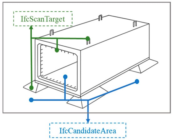
Figure 2.
Scanned target and candidate region information in the model.
Based on spatial information derived from BIM models, this study designed a site planning strategy prioritizing zoning. The effective scanning range of the Matterport Pro 2 panoramic camera is approximately 3 to 5 m. During site deployment, considering the field-of-view overlap between adjacent collection points, this overlap is typically set between 20% and 30% to ensure data continuity and model integrity during stitching. For areas with concentrated MEP embedded components, critical pipe joint ends, and waterstop transition zones, the system automatically increases point density to minimize potential blind spots and data gaps. Conversely, in unobstructed large spaces, station density is appropriately reduced to optimize equipment movement paths and capture efficiency.
During the collection phase in the precast submerged tunnel scenario, dense and similarly arranged reinforcement can reduce the availability of distinctive visual features in the scans, making inter-station scene alignment more difficult and increasing stitching errors in the reconstructed panoramic model. In addition, varying lighting conditions, including high-contrast illumination and low-light scenes, may introduce inconsistent illumination and shadows on scanned surfaces, which can further degrade acquisition stability and reduce the fidelity of the final 3D model.
To mitigate these issues, this study selected highly reflective target spheres as visual anchor points. These target spheres offer 360° visibility, enabling stable capture from any angle during Matterport Pro 2 panoramic scans and effectively mitigating recognition difficulties caused by obstructions. Target spheres were primarily deployed at embedded part positioning ports, corners with dense reinforcement layouts, and areas with pronounced elevation differences to enhance data alignment accuracy, as illustrated in Figure 3a.
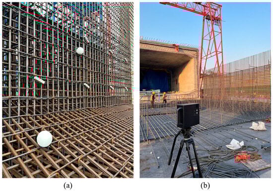
Figure 3.
Target ball placement and scene capture. (a) Target ball placement. (b) Panoramic model acquisition.
Following site setup and target ball marking, data collection proceeded point-by-point according to the plan. The 360° panoramic scan at each station was performed by the Matterport Pro 2 panoramic camera, with the acquisition method shown in Figure 3b. The Matterport Pro 2 camera integrates RGB imaging and depth information acquisition modules, with depth data obtained through multi-lens stereo vision and active infrared scanning technology. Specifically, the Matterport Pro 2 houses multiple cameras that calculate the relative depth of objects in space using stereoscopic vision principles. Each pair of cameras captures slightly offset images of the subject. The system precisely calculates the depth information for each pixel point using the triangulation method, based on the disparity magnitude and the distance between the cameras.
Additionally, the device incorporates an infrared emitter that actively projects infrared beams into the space. By analyzing the time difference and intensity variations in the reflected signals, it further refines spatial distance measurements. Compared to traditional single-point laser ranging, the Matterport Pro 2’s multi-lens stereoscopic vision simultaneously captures extensive depth data across a wide area. It automatically stitches together multi-angle data streams to generate a complete three-dimensional model.
3.1.2. Data Splicing and Scene Generation
After on-site data collection is completed, all scan data is automatically uploaded to the Matterport cloud platform, where it undergoes unified integration via its built-in multi-view stitching algorithm. Panoramic images and depth maps from each scan station undergo geometric correction and spatial alignment through cloud-based feature matching algorithms, ultimately generating a complete 3D scene model.
During the core data stitching process, the Matterport platform first extracts feature points from images at each capture station. It identifies local features using the SIFT (Scale-Invariant Feature Transform) algorithm [22], then calculates spatial transformation matrices between adjacent stations through spatial matching of multi-view feature points, completing the model’s geometric alignment. To enhance model stitching accuracy and completeness, the system pre-configures 20% to 30% field-of-view redundancy overlap during station collection. This ensures sufficient feature overlap between adjacent data blocks, preventing seam misalignment and information loss.
During the post-collection data processing phase, the Matterport cloud platform automatically outputs continuous 3D scene models. It supports exporting multiple data formats, including .obj and .xyz. The output models not only possess high-precision spatial geometry but also retain complete texture mapping and lighting details. All data is automatically mapped to a unified global coordinate system, ensuring high consistency with BIM model geometric alignment.
After generating the complete 3D scene model, Vuforia’s Area Target technology is employed to better support AR on-site recognition and alignment. The .obj model exported from the Matterport platform is imported into Vuforia Area Target Creator as spatial reference data for environmental feature analysis. Vuforia’s Area Target employs a spatial feature-based recognition method, extracting three-dimensional characteristics from the scene’s geometric information and key textures to generate an Area Target database. This database records unique spatial structures within the scene, including component edges, installation nodes, spatial corners, and other details.
After loading this Area Target database into the Unity engine, the system enables real-time spatial positioning and information display of components at the construction site. When an AR device enters the prefabricated pipe section construction site, the environmental features captured by the camera are compared and matched against the Area Target database. Upon successful matching, the system automatically performs spatial overlay and geometric alignment of virtual components, achieving high-precision virtual-physical synchronization and status visualization at the construction site.
As shown in Figure 4, the complete 3D scene model is successfully constructed, providing a high-precision data foundation for subsequent BIM-AR geometric registration and information fusion.
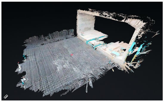
Figure 4.
Schematic diagram of the generated 3D scene model.
3.2. Accurate Matching of Model Geometry and Semantic Information
To achieve visual verification and human–machine interaction for pre-embedded components, it is essential to ensure high-precision spatial alignment between the submerged tunnel BIM model and on-site 3D scene data, while simultaneously extracting and accurately defining the semantic attributes of components. This study proposes an intelligent matching method tailored for prefabricated submerged tunnel construction, focusing on component geometric information and semantic information, in which geometric alignment between the BIM model and the panoramic model is achieved through automated multi-point spatial registration, and the corresponding semantic attributes are bound to each component via unique IDs to support consistent AR-based positioning and verification.
3.2.1. Intelligent Matching of Model Geometric Information
To achieve high-precision alignment of pre-embedded components within the three-dimensional on-site environment, this study proposes a BIM model registration method based on spatial consistency constraints using multiple reference points. In the experiments, three pairs of corresponding reference points were manually selected in the back-end from stable and easily identifiable structural features in both the BIM model and the 3D panoramic scene model. These points were located at geometrically distinctive and spatially separated features, including edge or corner regions on the end plate, side walls, and upper slab of the tunnel segment, in order to effectively constrain rigid pose estimation.
First, three sets of corresponding reference points are selected from both the BIM model and the 3D panoramic model:
Based on this set of matching points, define the optimal rigid transformation relationship between the two:
Here, denotes the rotation matrix and denotes the translation vector.
The rotation matrix is obtained by minimizing the sum of squares of registration errors:
This least-squares problem can be solved using singular value decomposition (SVD) [23] to obtain the optimal three-dimensional pose transformation parameters. Subsequently, the translation vector t is determined based on the coordinate differences in the reference points, ultimately completing the rigid alignment of the BIM model in three-dimensional space. The geometric registration results are shown in Figure 5.
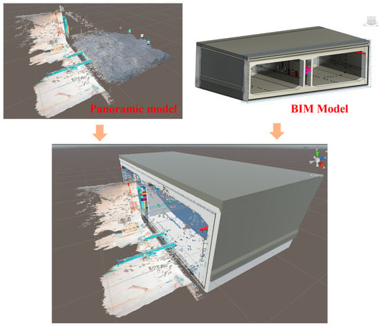
Figure 5.
Geometric registration results between the panoramic model and the BIM model.
Compared to traditional manual matching methods, this reference point alignment approach offers greater geometric certainty and spatial consistency, significantly improving registration efficiency while reducing human error. Its computational process is clear and efficient, making it suitable for implementation within the Unity environment and integration with AR systems. Upon completion of registration, the BIM model will serve as a visual component carrier within a unified spatial reference, providing reliable support for subsequent component visualization inspection and human–machine interaction.
It should be noted that the geometric registration establishes global spatial alignment between the BIM model and the panoramic scene, whereas quantitative accuracy evaluation is conducted at the component verification level, as reported in the experimental results.
3.2.2. Parsing and Matching of Model Semantic Information
Beyond achieving geometric registration of BIM models, further analysis and matching of component semantic information is required to enable property visualization and data-driven interactions for components within AR scenes.
This study employs Dynamo visual programming to automate the extraction of component property information from BIM models. As a Revit plugin, Dynamo can access and batch-read built-in parameter fields of components, outputting them in structured formats such as JSON or CSV. By writing reusable scripts, the system extracts all components required for visualization and records their unique identifiers (ID), categories, names, construction start/end dates, assigned floors, and other custom attributes. The relevant workflow is illustrated in Figure 6.
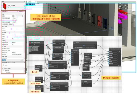
Figure 6.
Extracting component semantic information using Dynamo scripts.
The exported semantic information table corresponds to the geometric model and is imported into the Unity environment as intermediate data. During BIM model import into Unity, the system preserves the ID encoding within each component’s name field. This ID perfectly aligns with the ID field in the semantic information table. Leveraging this unique identifier, the system automatically completes semantic binding during model loading: structured attribute data is loaded as independent objects and attached to the corresponding component’s components, establishing a dual mapping relationship between geometry and attributes.
During semantic binding between the BIM model and Unity objects, the system performs an attribute completeness check after loading the semantic table and associating it with the corresponding components. If required semantic fields are missing or inconsistent, the system records a log entry containing the component ID and the specific fields with null or inconsistent values. These logs provide traceable evidence for identifying incomplete semantic definitions and support iterative refinement of the BIM semantic data, thereby maintaining the correctness and consistency of the geometry–attribute binding in the Unity environment.
To support late-stage BIM changes and reduce the risk of geometry–semantic desynchronization, the Dynamo-exported semantic table is treated as the source of truth for the current component ID list and attribute records. During each update, the Unity import module performs ID-based reconciliation between the newly exported table and existing records: newly introduced IDs are inserted as new records (and can be visually marked in the AR scene), while IDs missing from the latest export are marked as removed or archived to preserve traceability and avoid stale bindings. The update process follows the same ID-based binding and log reporting mechanism described above, so any ID-related inconsistencies are traceable and can be corrected during iterative model refinement. Under this mechanism, BIM changes are handled by re-exporting the updated semantic table (and model if geometry changes), enabling incremental updates without rebuilding the entire attribute table.
Through dual registration of geometric position and semantic attributes, the BIM model within the augmented reality scene not only achieves precise spatial correspondence with the construction site but also displays comprehensive attribute information. This provides a robust data foundation for dynamic interaction and information visualization at the construction site.
3.3. AR Human–Machine Interaction Application Development
To achieve visual guidance, real-time verification, and construction information management for pre-embedded components in immersed tube construction, this study developed a multi-terminal compatible, feature-rich, and flexible AR human–machine interaction system for immersed tube pre-embedded components. Building upon prior achievements in BIM-AR integration, the system focuses on three key aspects: multi-terminal device and interface adaptation, implementation of human–machine interaction modes, and application development.
3.3.1. Adaptation of Multi-Terminal Devices and Interactive Interfaces
To address the diverse application requirements across different roles, tasks, and operational conditions at submerged tunnel prefabrication sites, this study proposes a multi-terminal integrated human–machine interaction adaptation strategy. The system supports operation on both head-mounted AR devices (e.g., HoloLens 2) and handheld AR devices (e.g., iPad), ensuring consistent availability of component-level information visualization, status updates, and on-site inspection functions across multiple devices. Differentiated designs adapt to the operational characteristics and interaction logic of each device type.
At the device adaptation level, the system employs a cross-platform AR development framework. Built on the Unity engine, it integrates MRTK (Mixed Reality Toolkit) for spatial interaction development on the HoloLens 2 side and ARKit for image and spatial recognition on the iPad side. Both systems share unified data formats and component ID naming conventions at the underlying architecture level, ensuring critical functions—such as semantic information binding, progress simulation, and component status tagging—execute with identical data processing logic across terminals. For platform deployment, the HoloLens 2 side employs locally run spatial recognition and semantic loading mechanisms, while the iPad side combines local model rendering with lightweight interaction scripts to enhance responsiveness in mobile scenarios.
HoloLens 2, as a typical head-mounted AR terminal, is suitable for assembly guidance, spatial positioning, and immersive inspection scenarios. The system deploys spatial UI and natural interaction logic on this platform, employing a three-dimensional floating interface design, as shown in Figure 7a. The iPad, as a handheld AR terminal, is more suitable for mobile inspections, quick viewing, and status entry tasks. The system designed a touch-based interface with 2D controls for this platform, emphasizing clear functional access paths and efficient data entry. As shown in Figure 7b, the main interface comprises five primary areas: “Component Category,” “Component Information,” “Inspection Record,” “Progress Simulation,” and “Component Inspection.” The left side features a quick-filter menu where users can highlight specific components by category. The right side features an information panel where clicking a component displays its property details, enabling inspection record input and saving. The bottom houses a sliding timeline control for dynamically loading construction progress views, visually presenting component statuses at different time points. The center section contains a component inspection control for verifying the accuracy of pre-embedded components, locations, and quantities, among other specifications.
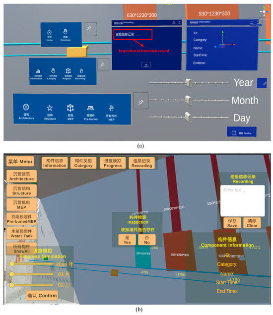
Figure 7.
Schematic diagram of AR interactive interface. (a) HoloLens 2 AR Interface. (b) iPad AR interface.
The entire interactive interface is optimized around the inspection logic of “view, select, judge, and record” in construction scenarios. Visually, the UI employs high-contrast color schemes, modular zoning, and large button controls to ensure smooth operation under complex outdoor lighting conditions and while wearing gloves. Visual feedback, button highlighting, and status transition prompts guide user actions, reducing misoperation rates.
Through unified data interfaces and adaptation strategies, the system achieves equivalent coverage of core functions across multi-terminal devices. It also optimizes operational methods and interface presentation based on device characteristics. The HoloLens 2 terminal enhances immersive positioning and hands-free operation capabilities, tailored for on-site assembly and inspection tasks by engineering personnel. The iPad terminal emphasizes intuitive interfaces and rapid data entry capabilities, suitable for management personnel conducting inspections and status tracking. This multi-terminal adaptation solution provides a stable, efficient, and scalable support framework for human–machine interaction among different roles at submerged tunnel construction sites.
3.3.2. Implementation of AR Human–Machine Interaction Modes
To meet the operational demands of multi-task scenarios at submerged tunnel construction sites, the system implements multiple natural human–machine interaction methods on terminals such as HoloLens 2 and iPad. It supports spatial perception operations and touch-based command input, providing efficient and intuitive interaction support for tasks like component recognition, status manipulation, and information recording.
On head-mounted AR devices like HoloLens 2, the system implements three core interaction mechanisms based on MRTK (Mixed Reality Toolkit): hand rays, press gestures, and voice commands. Hand ray interaction projects spatial rays using fingers as reference points to select structural components or UI controls. When the ray collides with a component, the system identifies the selected object and triggers the OnPointerClick event, invoking component information loading and interaction panel pop-up logic. This method enables rapid selection and operation without physical contact, making it suitable for light-touch scenarios like on-site inspections and information verification.
Simultaneously, the system implements press gesture interaction through MRTK’s PressableButton component. Users hover the gesture ray over a virtual button and perform a press action to trigger the button event, simulating traditional physical interaction. This mechanism significantly reduces accidental presses, ensuring clear interaction feedback and operation confirmation when managing construction statuses or reviewing conclusions.
To enhance usability in scenarios where hand gestures are restricted—such as complex environments or field operations—the system provides a voice command interface. Through the MRTK Speech Input system, predefined keyword commands like “Display Unfinished Components” or “Save Record” enable users to perform component filtering and information logging directly via voice. The system triggers actions based on key phrase recognition and command mapping tables, providing successful recognition feedback to enhance practicality and fault tolerance.
On handheld AR devices like iPads, the system employs a two-dimensional interaction method based on screen touch events. Users trigger component selection by tapping the visually overlaid BIM component models in the scene. The system then loads and displays corresponding attribute information through a component ID matching mechanism. All controls are built using Unity’s built-in UI system, bound to standard OnClick() event functions to handle component state changes, record inputs, and progress transitions. Interaction feedback mechanisms provide responsive cues through control highlighting and pop-up confirmations, ensuring users receive clear feedback during rapid operations.
Furthermore, considering the high-frequency, multi-tasking nature of mobile usage, the system incorporates optimized operation paths and grouped control zones. Primary controls are positioned on the left and top of the screen to avoid obstructing the field of view. Sensitive operations like state modifications and information input employ double-confirmation designs to prevent accidental touches.
By integrating spatial and touch-based input mechanisms, the system achieves a natural extension of the user experience across different terminals, balancing immersive engagement with mobile operational efficiency. This diverse approach to interaction not only enhances the system’s adaptability to complex construction environments but also provides more flexible human–machine interaction entry points for users in different roles.
3.3.3. Development of AR Human–Machine Interaction Applications
To support core tasks such as component identification, status assessment, and construction progress analysis at the precast submerged tunnel fabrication site, this system builds a Unity-based AR human–machine interaction application module centered around 3D models, semantic information, and interactive logic.
For visual construction guidance and position verification, the system uses Vuforia Area Target positioning results to overlay lightweight, registered BIM models onto real-world scenes within a unified coordinate system, achieving spatial consistency between virtual and physical models. Field personnel wearing or holding AR devices can observe the design positions of pre-embedded components within the scene and visually compare them against actual installation locations. When a user selects a pre-embedded component via tap or gesture, the system displays a confirmation prompt, prompting the user to determine whether the component is accurately installed. Users can mark the component status by clicking “Yes” or “No” buttons. The system automatically assigns different color materials to the component based on the user’s selection, enabling visual status representation.
Component status information is recorded in semantic attributes. Modification operations are performed through script interfaces attached to the component objects, facilitating unified querying and dynamic updates of inspection statuses by subsequent construction management personnel.
For component information display, the system loads semantic property references at each node. Upon user interaction with a component, it retrieves preloaded data structures via the component ID to generate a floating property panel. This panel displays the component’s ID, type, dimensions, planned schedule, and other details. The HoloLens 2 interface employs a World Space Canvas layout, anchoring the panel to float alongside the component. The iPad interface utilizes an in-screen pop-up card panel to enhance touch response speed and visual clarity. The property panel maintains a bidirectional binding with the component object, fetching displayed information in real-time from the semantic data structure without secondary searches or external API requests.
The component filtering module incorporates a multi-condition filtering logic controller based on semantic fields. This module supports setting filter criteria across dimensions such as component type, status, floor level, or construction phase. Upon user selection of any combination of conditions, the system iterates through the component set, retrieves bound information, and dynamically updates the display state based on the filtering results. The filtering logic uses scripts to control component visibility, hiding non-target components to ensure priority display of target components within the field of view. The filter supports real-time condition changes, with interface operations triggered via button controls and other commands.
For construction progress simulation implementation, the system builds a component plan status dictionary based on a “time-component” mapping table, enabling users to load construction plan statuses by time node. The progress panel functions as a timeline control. Users set simulation timepoints via sliders or date pickers, prompting the system to retrieve corresponding component sets and display planned-to-be-completed components within the 3D scene. Users can visually verify alignment between actual installed components and planned status on-site, enabling construction progress visualization and verification.
All modules form a closed-loop logic through component IDs as the connecting link. Dynamic interactions across all functions are realized based on the unique identifiers of components within Unity and their pre-bound semantic data. Interface states, attribute displays, and user operations are all visually reflected in real time within the scene. This structure effectively meets the on-site requirements for component status assessment, information viewing, and progress comparison, laying the functional foundation for subsequent status coordination and multi-user management.
3.4. AR Human–Machine Collaborative Management of Multi-Terminal Devices
The construction process of pre-embedded components in submerged tunnel involves parallel operations and information exchange among multiple specialized teams. Construction personnel, quality inspectors, and project managers are often dispersed across different work sections, requiring real-time updates and feedback on component installation progress, quality status, and inspection records. Traditional data transmission methods—relying on paper forms, verbal communication, or manual data entry—suffer from low efficiency, information delays, and version inconsistencies, failing to meet the real-time and consistent requirements for component-level status management.
To address this challenge, this study developed a multi-terminal AR collaborative management system based on spatial anchor synchronization and status broadcasting mechanisms. This system enables users of different roles to share the same augmented reality environment on their respective devices, achieving synchronized updates and consistent data access for component statuses. The system integrates Azure Spatial Anchors (ASA) and Photon Unity Networking (PUN) technologies, respectively, for cross-device spatial alignment and real-time communication broadcasting, forming a multi-terminal collaborative interaction framework for submerged tunnel construction sites.
3.4.1. Spatial Sharing and Communication Coordination
To support multi-role collaborative inspections of pre-embedded components in submerged tunnel, this system establishes a multi-terminal AR interaction model based on spatial consistency and state-sharing mechanisms. It enables construction personnel, quality inspectors, and managers to perform component-level operations simultaneously across different devices while maintaining information synchronization and state consistency, as illustrated in Figure 8.
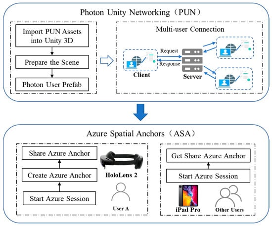
Figure 8.
Principle of multi-terminal collaborative and status synchronization.
The system employs Augmented Spatial Anchoring (ASA) technology to establish spatial anchors at the construction site, calibrating the unified physical positioning of BIM models. HoloLens 2 devices can create and upload anchors, while devices like iPads automatically calibrate model overlay positions by recognizing identical anchors. This ensures virtual components displayed across terminals from different perspectives reside within the same physical coordinate system, achieving spatially consistent collaboration.
Building upon this foundation, the system employs network communication mechanisms to share and synchronize component statuses. When a user marks a component as “Completed” on the HoloLens 2, this action is broadcast in real time to all online devices. Other users viewing the same component will see the updated status, preventing duplicate actions and data conflicts.
This mechanism enables personnel across multiple roles to conduct parallel inspections and collaborative documentation within the same AR scene. Unified component IDs and status fields ensure data consistency. For instance, after construction workers make markings, managers can immediately confirm them, add notes, or review results, forming a complete closed-loop workflow.
Through the integrated application of spatial anchor alignment and status synchronization mechanisms, the system effectively supports multi-terminal, multi-role collaborative inspection tasks during submerged tunnel construction, enhancing information transmission efficiency and the accuracy of component status management.
3.4.2. Inspection Records and Collaborative Management
To achieve visual annotation of component status and unified information management, the system integrates an AR inspection recording mechanism based on ID mapping across multi-terminal devices.
Content entered in the front-end interface is temporarily cached in a local data structure. Upon confirmation, it is packaged into data items via standardized interfaces and sent to the server in JSON format. The system backend calls the MySQL database to write corresponding records into the component table. The data structure uses the component ID as the primary key, storing fields such as inspection time, status, text notes, and image paths.
All data write operations simultaneously trigger server update events to notify other terminals to refresh local component statuses, ensuring data consistency. The database supports ID- and time-based query indexes, enabling on-demand historical component traceability and providing structured support for subsequent data analysis and verification.
In summary, the multi-terminal AR collaborative management framework developed by this system achieves real-time synchronization of construction status and ensures information consistency across devices and positions through spatial anchor sharing, status broadcast mechanisms, and database-driven task coordination. The system not only supports operational collaboration among construction personnel but also provides managers with reliable progress monitoring and issue traceability capabilities.
4. Experiments
To validate the practicality and feasibility of the proposed BIM- and AR-based human–machine collaborative management system for pre-embedded components in submerged tunnel segments, this study conducted system deployment and field experiments at the Nansha Mingzhu Bay submerged tunnel project in Guangzhou. This project represents a typical large-scale submerged tunnel, featuring prefabricated segments approximately 100 m in length. The pre-embedded components exhibit diverse types, dense distribution, and complex spatial layering, providing excellent representativeness for system testing.
The ES2-1 pipe section was selected as the sample area for comprehensive application testing, including data collection, model registration, AR interactive display, component positioning verification, and multi-terminal collaborative operations. The project site and experimental area are shown in Figure 9, while the deployed equipment and platforms are listed in Table 1.
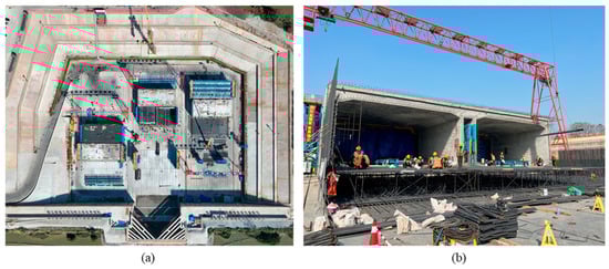
Figure 9.
Site view of the experimental area and system deployment diagram. (a) Aerial view of the project dry dock site. (b) Actual scene at the experimental site.

Table 1.
Experimental equipment and platforms.
Achieving precise and stable AR positioning of pre-embedded components in the complex and constantly changing environment of a submerged tunnel precast tunnel segment site requires comprehensive 3D scene capture. The experiment tracked and captured data throughout the entire precast process, documenting construction scenes at the tunnel segment’s bottom, ends, and top. The on-site experimental setup is illustrated in Figure 10, ultimately generating a complete 3D scene of the precast tunnel segment.
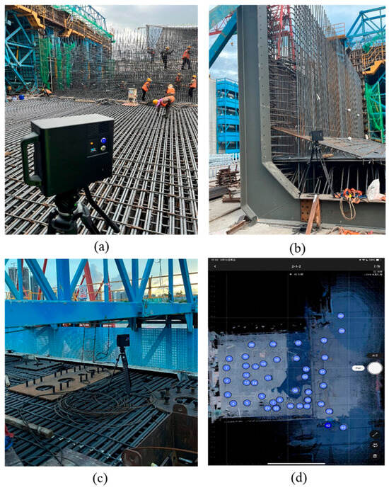
Figure 10.
Scene capture of the precast submerged tunnel experiment. (a) Bottom scene capture. (b) End-point scene capture. (c) Top scene capture. (d) Panoramic model acquisition sites.
Through the integration of the aforementioned equipment and comprehensive scene capture, the system achieves full-process operation of key functional modules including AR model display, component verification, status management, and terminal collaboration within predefined scenarios.
4.1. Pre-Embedded Components Positioning and Verification Experiment
This experiment aims to evaluate the capability of the developed BIM-AR system to support spatial positioning accuracy and visualization verification efficiency for pre-embedded components in prefabricated submerged tunnel construction scenarios. Testing focuses on the accuracy of component geometric positioning and terminal interaction responsiveness, verifying its practical value in complex construction sites.
The experimental subjects encompassed seven categories of typical pre-embedded components for submerged tunnel, including top outfitting embedments, end steel shells, end closure door embedments, vertical shear keys, waterstops, MEP embedments, and tank embedments, totaling 80 test samples. The samples were selected to represent various tunnel segment locations (end sections, central segments, and junction areas), different stages of the prefabrication process (bottom, side, and top positions), and varying complexities (mechanical, electrical, and structural elements). Additionally, worst-case scenarios, such as reinforcement shielding or obstructions affecting visual alignment, were considered to ensure comprehensive evaluation of the system’s performance under typical and challenging conditions.
In current practice, verification of pre-embedded components is commonly performed using manual measurements, and in some cases with total station surveying or laser scanning. Manual measurement remains a widely used on-site baseline due to its simplicity and accessibility, and is therefore adopted as the reference method in this study. Compared with total station or laser scanning workflows that often require additional equipment setup and post-processing, the proposed BIM- and AR-based method provides real-time AR overlay and intuitive visual comparison between the as-installed components and the BIM model, enabling faster on-site verification in complex construction environments.
Experiments were conducted on both HoloLens 2 and iPad devices, representing two typical scenarios: immersive spatial interaction and mobile touchscreen operation. The experimental procedure involved loading the calibrated BIM model with semantic information. Following component installation, AR scanning of pre-embedded components was performed. Testers selected target components via the device interface, triggered information displays, and executed verification judgments. Concurrently, two engineers conducted manual measurements using structural rulers and recorded verification times as a comparative baseline. The test site is illustrated in Figure 11.
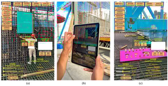
Figure 11.
Pre-embedded components positioning and verification experiment. (a) On-site scanning of MEP pre-embedded components. (b) Field sweep at the end. (c) On-site scanning of top outfitting components.
As shown in Table 2, the experimental results demonstrate that the system exhibits high pre-embedded component recognition and verification capabilities on both terminals. Regarding average positioning deviation, the iPad terminal recorded 1.22 cm and the HoloLens 2 terminal 1.78 cm, both of which meet the verification accuracy requirements for pre-embedded components in large-scale precast submerged tunnel scenarios, with both measurements staying under 2 cm.
Table 2.
Experimental results.
However, positioning errors vary across different component types. For example, outfitting components located near the upper slab are often affected by dense formwork and rebar, which increases occlusion and reduces scanning visibility, resulting in relatively higher positioning deviations. In contrast, shear keys exposed near tunnel ends provide clearer geometric features and better multi-angle observability, and therefore exhibit lower deviations and higher accuracy. In addition, working conditions such as lighting variations and rebar interference can further amplify deviations in areas with more severe occlusion.
For verification efficiency, the iPad platform demonstrated significant advantages in operational speed and interface responsiveness, with an average verification time of 1.5 s per component, significantly lower than the 7.0 s required for manual operations. This highlights a substantial efficiency improvement. The HoloLens 2 platform provided stable recognition without requiring handheld operation, making it suitable for scenarios with limited space or where hands-free operation is necessary. The combination of both devices supports diverse operational needs, offering flexible and efficient component verification solutions for submerged tunnel construction scenarios.
4.2. Information Query and Human–Machine Interaction Application Experiment
To validate the system’s visualization, interactivity, and multi-terminal adaptability for pre-embedded component semantic information in precast submerged tunnel segment construction scenarios, this study conducted component information query and human–machine interaction experiments on two terminal types: HoloLens 2 and iPad Pro. The experimental subjects were typical pre-embedded components with completed geometric and semantic binding, whose attribute information included ID, category, name, construction schedule, etc.
Regarding interaction implementation, when a user selects a component on the terminal interface, the system automatically displays a corresponding interface presenting the component’s interactive information. On the HoloLens 2 platform, the information interface appears as a floating window in the virtual space, with users performing selection operations via hand ray gestures or presses. On the iPad platform, the system loads information through touch clicks and pop-up cards. Both terminals maintain consistent interaction logic, ensuring uniformity in semantic data loading and multi-device usability.
On the iPad, experimenters can query, filter, and manage component information through touch interactions, as shown in Figure 12. The system employs a graphical interface design where users can tap components to pop up attribute cards displaying category, ID, and construction progress. It also supports multi-dimensional filtering by attributes such as component type and construction time, facilitating rapid target identification within complex component clusters. Experimental testing demonstrates that the iPad Pro delivers stable performance in semantic information loading, component highlighting responsiveness, and screen rendering. With clear interaction logic and rapid response times, it proves suitable for mobile rapid inspection and multi-scenario information retrieval operations.
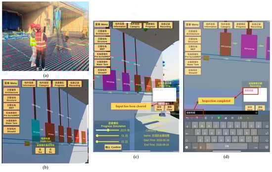
Figure 12.
On-site human–machine interaction experiment on iPad. (a) iPad On-site interactive application. (b) Pre-embedded components inspection. (c) Interaction of pre-embedded components. (d) Information recording.
On the HoloLens 2 side, experimenters wearing AR headsets can visually inspect the BIM 3D model of the immersed tube directly at the actual prefabrication site. The model overlays in real time with the actual environment, achieving an immersive display that merges virtual and real elements. As shown in Figure 13, the system supports component selection, hiding, and property panel access via gesture controls. Construction personnel can directly inspect the spatial positioning and installation status of embedded components within the field of view. Upon selecting a target component, the system instantly loads its corresponding semantic information. Experimental testing demonstrates that the HoloLens 2 platform delivers smooth model rendering with stable frame rates, effectively supporting spatial verification and concealed work inspections at precast pipe installation sites.
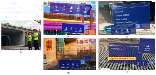
Figure 13.
On-site human–machine interaction experiment with HoloLens 2. (a) HoloLens 2 on-site interactive application. (b) Component selection interaction. (c) Semantic information query and display. (d) Construction progress simulation. (e) Information records.
Additionally, regarding semantic information query response times, the iPad averaged 0.3 s while the HoloLens 2 averaged 0.8 s. The accuracy rate for semantic information display was 100% on both platforms, indicating a stable and reliable semantic mapping mechanism. Test feedback revealed that the HoloLens 2 exhibited noticeable field-of-view reflections under intense outdoor lighting conditions, affecting interface clarity. In contrast, the iPad’s high-brightness display and touch-based interaction proved superior in such environments.
Experimental validation demonstrates that while maintaining consistent functional logic, each terminal exhibits distinct advantages suited to different construction roles and task scenarios. The iPad terminal offers superior portability and interactive flexibility, while the HoloLens 2 terminal delivers enhanced spatial visualization and immersive interaction. Both maintain consistent functional logic and data synchronization, effectively meeting the needs of diverse roles and operational contexts.
4.3. AR Collaborative Management Application with Multi-Terminal Devices
During the construction of pre-embedded components for submerged tunnel, construction personnel, quality inspectors, and managers are often dispersed across different areas. This necessitates real-time collaborative sharing for component status updates, issue logging, and information feedback. In field experiments, construction personnel completed component status updates and issue logging on HoloLens 2 devices. Other users could view these updates in real time on iPad devices and perform subsequent operations such as filtering and querying. The experimental setup and database information recording are illustrated in Figure 14. Results indicate consistent content display across all terminals. The HoloLens 2 system response exhibited a frame rate range of 34.6–44.8 fps, meeting application requirements for information responsiveness. Concurrently, inspection data recorded across multiple terminals was centrally managed within the database, significantly enhancing information sharing and communication efficiency at the project site.
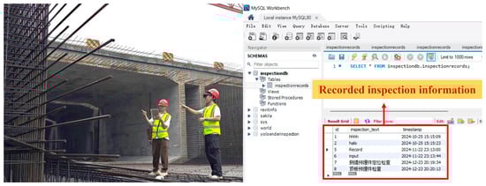
Figure 14.
Multi-terminal collaboration scenario and information recording.
The experiment focuses on validating the collaborative data management capabilities and the visual display effects across multiple terminals. While it demonstrates efficient data synchronization and multi-terminal interaction, it does not directly measure metrics such as duplicate operations or desynchronization. These will be explored in future experiments.
4.4. Experimental Summary
The AR inspection system designed in this study demonstrated stable and efficient practical performance during experiments at the Guangzhou Nansha submerged tunnel project. In positioning and verification tests, the average positioning deviation for the iPad and HoloLens 2 platforms was 1.22 cm and 1.78 cm, respectively, achieving centimeter-level positioning accuracy at the pre-embedded component verification level, which meets the practical requirements for large-scale submerged tunnel prefabrication scenarios. These deviations reflect the end-to-end performance of the BIM–AR inspection workflow under real construction conditions, rather than isolated geometric registration residuals.
The iPad platform leveraged touch interaction to achieve higher operational efficiency, with an average component verification time of 1.5 s—significantly outperforming the manual average of 7.0 s. While the HoloLens 2 interface involved slightly higher interaction complexity, its hands-free nature made it more suitable for field operations in confined spaces or scenarios requiring both hands.
In semantic information queries and human–machine interaction experiments, the system enables rapid filtering and highlighted positioning through semantic fields like component category and floor zoning. Query response times were 0.3 s on iPad and 0.8 s on HoloLens 2, demonstrating stable and accurate field interaction across all terminals. Furthermore, in multi-terminal collaboration experiments, the system achieved stable cross-device data sharing through spatial anchor alignment mechanisms and network status synchronization modules. Overall experimental results validate the system’s spatial accuracy, data linkage, and collaborative responsiveness in complex construction environments, providing a viable digital solution for managing construction of pre-embedded components in submerged tunnel projects.
5. Conclusions
This study proposes a BIM-AR human–machine collaborative management method for pre-embedded components in prefabricated submerged tunnel segments. The system implements an end-to-end workflow that couples panoramic scene reconstruction, automated geometry–semantic alignment, AR-based on-site verification, and centralized multi-terminal inspection data management. Compared with prior work that is mainly conceptual or limited to single-device demonstrations, this project provides project-level validation and a closed-loop engineering workflow for on-site component verification.
Experimental results demonstrate accuracy and efficiency gains on two representative terminals. The iPad achieved an average positioning deviation of 1.22 cm and an average verification time of 1.5 s per component, showing substantial efficiency improvement over manual checks. The HoloLens 2 obtained an average positioning deviation of 1.78 cm while providing stable hands-free spatial visualization for in situ verification. These device differences primarily reflect their interaction and display characteristics: the iPad favors rapid touchscreen operations, whereas HoloLens 2 supports immersive, hands-free inspection in constrained or spatial tasks.
Nevertheless, this study faces certain limitations that need to be addressed before practical application:
- (1)
- Impact of environmental factors: dense reinforcement and unstable outdoor lighting can reduce panoramic reconstruction fidelity. Future work will select more reliable features or visual anchors in highly occluded areas and optimize the panoramic camera lighting setup to improve acquisition stability.
- (2)
- Generalizability: the system’s evaluation was conducted in a single pilot case. Future work will undertake multi-project validation across different submerged tunnel segments and construction environments and compare the proposed approach with other AR platforms and alternative verification solutions.
- (3)
- Multi-terminal collaboration performance: synchronization metrics were not quantitatively assessed in the present experiments. Future work will collect key metrics (response time, desynchronization frequency, and duplicate operations) to evaluate synchronization stability and scalability across devices.
Author Contributions
Conceptualization, B.W., X.S. and Y.Z. (Youde Zheng); methodology, Y.Z. (Youde Zheng), X.S. and Y.T.; software, Y.Z. (Youde Zheng); validation, B.W., J.G. and G.Z.; formal analysis, C.P. and X.W.; investigation, X.S. and X.X.; resources, J.G. and B.W.; data curation, G.Z.; writing—original draft preparation, Y.Z. (Youde Zheng); writing—review and editing, Y.Z. (Youde Zheng) and Y.T.; visualization, C.P. and Y.Z. (Yufa Zhang); supervision, B.W. and X.W.; project administration, Y.Z. (Yufa Zhang) and X.X.; funding acquisition, Y.T. All authors have read and agreed to the published version of the manuscript.
Funding
This research was funded by the National Natural Science Foundation of China (NSFC) (grant number 52308319) and the Shenzhen University 2035 Program for Excellent Research (2022B007).
Data Availability Statement
The raw data supporting the findings of this study are not publicly available due to privacy or ethical restrictions. However, processed data supporting the conclusions are available from the corresponding author upon reasonable request.
Conflicts of Interest
Authors Ben Wang, Junwei Gao, Chao Pei, Yufa Zhang and Xu Xiang were employed by the company China Railway Tunnel Group Co., Ltd. The remaining authors declare that the research was conducted in the absence of any commercial or financial relationships that could be construed as a potential conflict of interest.
References
- Wu, F.L.; Liu, F.X.; Ma, D.S. Technology for super long distance floating transportation of immersed tubes. China Harb. Eng. 2024, 44, 1–5. [Google Scholar] [CrossRef]
- Guo, J.; Shan, L.; Ma, M. Statistics Analysis and Development of Immersed Tube Tunnels in China. Tunn. Constr. 2023, 43, 173–184. Available online: https://kns.cnki.net/kcms2/article/abstract?v=f0DSObGwzqjc9vBOWCox6x4_Kn00-qCZfo4CEG5JYSAxow179QHozEGMcGdYAs2fPS77WPeW2smezMPYq2TjadUco2EFOqe5YbZuwsrasclE8oBSphKIy_1VMjZx263t_W0M-wJDsyGsAFhdjwP1AL7VT_jfe6XbOiqAd9-rlF_5xlGQk-uN1g==&uniplatform=NZKPT&language=CHS (accessed on 23 December 2025).
- Ding, H.; Jing, Q.; Yan, Y.; Zhang, N.; Li, W.L. Overview of the current status of operation and maintenance technology for immersed tube tunnels. China J. Highw. Transp. 2022, 35, 1–12. [Google Scholar] [CrossRef]
- Vignali, V.; Acerra, E.M.; Lantieri, C.; Di Vincenzo, F.; Piacentini, G.; Pancaldi, S. Building information Modelling (BIM) application for an existing road infrastructure. Autom. Constr. 2021, 128, 103752. [Google Scholar] [CrossRef]
- Chu, M.; Matthews, J.; Love, P.E. Integrating mobile building information modelling and augmented reality systems: An experimental study. Autom. Constr. 2018, 85, 305–316. [Google Scholar] [CrossRef]
- Al-Sabbag, Z.A.; Yeum, C.M.; Narasimhan, S. Interactive defect quantification through extended reality. Adv. Eng. Inform. 2022, 51, 101473. [Google Scholar] [CrossRef]
- Catbas, F.N.; Luleci, F.; Zakaria, M.; Bagci, U.; LaViola, J.J., Jr.; Cruz-Neira, C.; Reiners, D. Extended reality (XR) for condition assessment of civil engineering structures: A literature review. Sensors 2022, 22, 9560. [Google Scholar] [CrossRef]
- Xin, L. Application of BIM Technology in the Island-Tunnel Project of Shenzhen-Zhongshan Channel. China Harb. Eng. 2024, 44, 116–122. [Google Scholar] [CrossRef]
- Cao, Y.F.; Wang, Y.; Peng, X.Y.; Liu, H.Z.; Zhang, H.J.; Lu, Z.K.; Liu, X. Research and Application of Digital Design Software for Tunnel Engineering Based on BIM Technology. Highway 2025, 70, 340–347. Available online: https://link.cnki.net/urlid/11.1668.U.20250311.1417.004 (accessed on 23 December 2025).
- Pan, L.W.; Zhang, Y.X.; Xu, L.; Tian, Z.X. Analysis and Control Methods for Mileage Deviation in Immersed Tube Tunnel Installation. China Harb. Eng. 2022, 42, 72–75. [Google Scholar] [CrossRef]
- Han, X.J.; Li, L.; Ren, K.L. Research on Key Construction Technologies for Submerged Tunnel Segments in Cross-River Tunnels. Technol. Innov. Appl. 2023, 13, 172–175. [Google Scholar] [CrossRef]
- Liu, J.; Gu, S.K.; Lin, J.; Li, M. Digital Engineering Construction and Application of the Dalian Bay Undersea Tunnel. China Harb. Eng. 2024, 44, 113–118. [Google Scholar] [CrossRef]
- Al-Sabbag, Z.A.; Yeum, C.M.; Narasimhan, S. Enabling human–machine collaboration in infrastructure inspections through mixed reality. Adv. Eng. Inform. 2022, 53, 101709. [Google Scholar] [CrossRef]
- KAmmari, E.; Hammad, A. Remote interactive collaboration in facilities management using BIM-based mixed reality. Autom. Constr. 2019, 107, 102940. [Google Scholar] [CrossRef]
- Mirshokraei, M.; De Gaetani, C.I.; Migliaccio, F. A web-based BIM–AR quality management system for structural elements. Appl. Sci. 2019, 9, 3984. [Google Scholar] [CrossRef]
- Ogunseiju, O.R.; Gonsalves, N.; Akanmu, A.A.; Bairaktarova, D.; Bowman, D.A.; Jazizadeh, F. Mixed reality environment for learning sensing technology applications in Construction: A usability study. Adv. Eng. Inform. 2022, 53, 101637. [Google Scholar] [CrossRef]
- Wagner, M.; Leubner, C.; Strunk, J. Mixed reality or simply mobile? A case study on enabling less skilled workers to perform routine maintenance tasks. Procedia Comput. Sci. 2023, 217, 728–736. [Google Scholar] [CrossRef]
- Chen, H.; Hou, L.; Zhang, G.K.; Moon, S. Development of BIM, IoT and AR/VR technologies for fire safety and upskilling. Autom. Constr. 2021, 125, 103631. [Google Scholar] [CrossRef]
- Diao, P.-H.; Shih, N.-J. BIM-based AR maintenance system (BARMS) as an intelligent instruction platform for complex plumbing facilities. Appl. Sci. 2019, 9, 1592. [Google Scholar] [CrossRef]
- Tan, Y.; Xu, W.; Chen, P.; Zhang, S. Building defect inspection and data management using computer vision, augmented reality, and BIM technology. Autom. Constr. 2024, 160, 105318. [Google Scholar] [CrossRef]
- Chalhoub, J.; Ayer, S.K. Using Mixed Reality for electrical construction design communication. Autom. Constr. 2018, 86, 1–10. [Google Scholar] [CrossRef]
- Lowe, D.G. Distinctive Image Features from Scale-Invariant Keypoints. Int. J. Comput. Vis. 2004, 60, 91–110. [Google Scholar] [CrossRef]
- Pan, C.T.; Sigmon, K. A Bottom-Up Inductive Proof of the Singular Value Decomposition. SIAM J. Matrix Anal. Appl. 1994, 15, 59–61. [Google Scholar] [CrossRef]
Disclaimer/Publisher’s Note: The statements, opinions and data contained in all publications are solely those of the individual author(s) and contributor(s) and not of MDPI and/or the editor(s). MDPI and/or the editor(s) disclaim responsibility for any injury to people or property resulting from any ideas, methods, instructions or products referred to in the content. |
© 2025 by the authors. Licensee MDPI, Basel, Switzerland. This article is an open access article distributed under the terms and conditions of the Creative Commons Attribution (CC BY) license.