Article

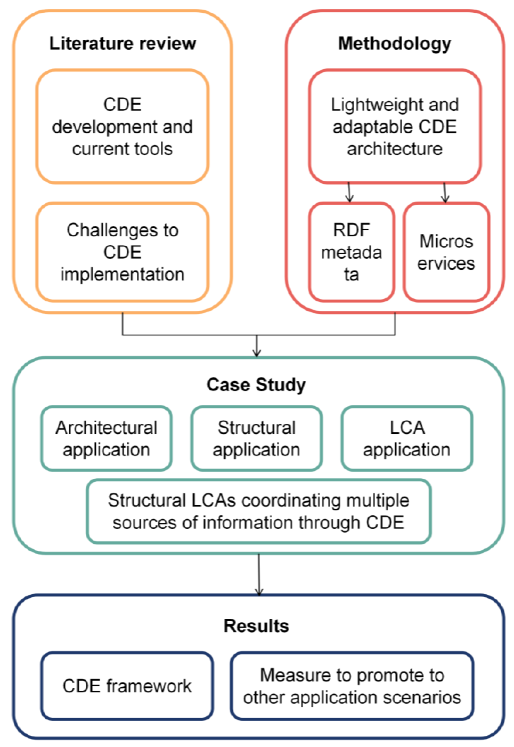
A Common Data Environment Framework Applied to Structural Life Cycle Assessment: Coordinating Multiple Sources of Information

by
Lini Xiang
1,
Gang Li
1,* and
Haijiang Li
2
1
State Key Laboratory of Structural Analysis Optimization and CAE Software for Industrial Equipment, Department of Engineering Mechanics, Dalian University of Technology, Dalian 116024, China
2
BIM for Smart Engineering Centre, School of Engineering, Cardiff University, Cardiff CF24 3AA, UK
*
Author to whom correspondence should be addressed.
Buildings 2025, 15(8), 1315; https://doi.org/10.3390/buildings15081315
Submission received: 21 February 2025 / Revised: 13 April 2025 / Accepted: 14 April 2025 / Published: 16 April 2025
(This article belongs to the Section Construction Management, and Computers & Digitization)

Abstract

In Building Information Modeling (BIM)-driven collaboration, the workflow for information management utilizes a Common Data Environment (CDE). The core idea of a CDE is to serve as a single source of truth, enabling efficient coordination among diverse stakeholders. Nevertheless, investigations into employing CDEs to manage projects reveal that procuring commercial CDE solutions is too expensive and functionally redundant for small and medium-sized enterprises (SMEs) and small research organizations, and there is a lack of experience in using CDE tools. Consequently, this study aimed to provide a cheap and lightweight alternative. It proposes a three-layered CDE framework: decentralized databases enabling work in distinct software environments; resource description framework (RDF)-based metadata facilitating seamless data communication; and microservices enabling data collection and reorganization via standardized APIs and query languages. We also apply the CDE framework to structural life cycle assessment (LCA). The results show that a lightweight CDE solution is achievable using tools like the bcfOWL ontology, RESTful APIs, and ASP.NET 6 Clean architecture. This paper offers a scalable framework that reduces infrastructure complexity while allowing users the freedom to integrate diverse tools and APIs for customized information management workflows. This paper’s CDE architecture surpasses traditional commercial software in terms of its flexibility and scalability, facilitating broader CDE applications in the construction industry.

1. Introduction

Building Information Modeling (BIM) is designed to support activities ranging from initial design and planning through construction execution to facility management and operations. However, the BIM-facilitated collaboration reconciling different data created by distinct systems, product models, and estimation processes [1] is complex. The concept of Common Data Environment (CDE) has emerged, which is more suitable than BIM in information management workflow in the construction industry. At its heart, the CDE functions as the single source of information for all involved parties for any built asset [2]. It ensures that everyone, from architects and engineers to contractors and project owners, works on the same and most current set of information. In addition, CDEs use a distributed infrastructure [3]. By doing so, it enables seamless and efficient coordination among a diverse array of stakeholders. Each stakeholder can retrieve what they need without the risk of data duplication or corruption. A CDE significantly enhances decision-making processes throughout the lifecycle of a construction project [2]. Thus, adopting a CDE in BIM-driven workflows represents a significant leap forward in managing and executing construction projects.
In 2019, the international standard ISO19650 [4] guiding CDE implementation was established, which provides a structured approach for managing information over the entire lifecycle of assets. Additionally, regional and national regulations (e.g., DIN SPEC 91,391 [5]) also shape the application of CDEs. Since then, the landscape of CDE tools has rapidly evolved. Commercial platforms such as Autodesk’s BIM 360, Bentley’s ProjectWise, and Trimble’s Viewpoint lead the way. Commercial software offers a comprehensive suite of tools, powerful integration interfaces, and a unified data infrastructure architecture that allows different teams to work collaboratively using a variety of file formats and applications. However, procuring commercial CDE solutions is too expensive and functionally redundant [6] for small and medium-sized enterprises (SMEs) and small research organizations, and there is a lack of experience regarding the use of CDE tools [6].
Given evolving BIM-driven workflows, more and more researchers are focusing on the state of the art of CDE in practice, and several approaches to developing CDE using different technologies have emerged. An example is using open standards to create a CDE framework for facility management [7]. In addition, using linked data to develop information containers served as the core of a CDE [8], which also makes sense, as does integrating CDE access into an electronic document management (EDM) system [9]. Other examples are combining the BIM management system (BIMMS) and the Semantic Web technology to build a collaborative platform [10] or using blockchain for storing data from sensitive digital infrastructures [11,12]. However, most CDE technology solutions are oriented to specific scenarios, and these CDE architectures are not sufficiently compatible and adaptable. Further research is needed on easily accessible and flexible open-source tools to develop lightweight CDE solutions that developers can quickly migrate to other application scenarios.
This paper addresses the research gaps above by creating a flexible and extendable CDE architecture that combines two tools: resource description framework (RDF) metadata and cloud-based microservices. We validate the proposed CDE architecture in the structural domain through a structural life cycle assessment (LCA) case study. Compared to the existing commercial software and CDE architectures developed by other technologies, our approach is more flexible, lighter, and easier to expand. In addition, the detailed development process and the availability of relevant digital tools also make this paper conducive to generalizing the CDE practice to a broader range of applications.

2. Literature Review

2.1. RDF in CDE

Unlike BIM, a CDE’s primary role is efficient information management and collaboration, ensuring real-time updates, version control, and access management [13]. Both commercial CDE software ProjectWise 2023 and Autodesk® Docs 2025 and cutting-edge CDE framework research mostly use RDF as the data infrastructure, providing a unified semantic description framework for different datasets. The first benefit is metadata management. In construction projects, each source of information contributes specific types of information, such as blueprints, specifications, contracts, models, and more. Crucial details might be scattered across different platforms or formats, making it challenging to maintain a coherent overview of the project [2]. While Industry Foundation Classes (IFC) ISO16739 [14] has made strides towards universal exchange standards [15], the RDF is used in the next generation of open data standards [16]. Many RDF tools, robust standards, and protocols [17] emerged. Include data stores (e.g., Apache Jena, GraphDB), visualization tools (e.g., Ontotext), and development environment (e.g., Protégé, RDFLib library). Creating metadata annotation with RDF for domain datasets is a prerequisite for retrieving project information.
The second benefit is version control. Using RDF metadata to record version changes makes it possible to trace back to any historical version [18,19]. RDF uses Uniform Resource Identifiers (URIs) to uniquely identify each data item for cross-system linking and referencing. Through linked data technology [20], data sets from different systems are connected to form a comprehensive data view. When a data item changes, the relevant stakeholders are automatically updated. Subsequently, search and filtering operations are performed on the RDF graph using the SPARQL query language.
The third benefit is access management. Managing access to a CDE’s vast amounts of sensitive data presents trouble. Ensuring that only authorized personnel can view or modify certain information while maintaining transparency and easy access for relevant stakeholders requires sophisticated authority mechanisms [21]. Furthermore, as projects evolve, so must the CDE’s capabilities to support ongoing modifications. RDF technology provides the standardization of data entry, information updates, and access methods, maintaining consistency of data handling between numerous contributors of a CDE [22]. Finally, robust APIs and middleware solutions [23] can make real-time synchronization and version control practical across all connected systems.

2.2. Microservices in CDE

A CDE uses distributed data containers to represent multiple stakeholders in a joint project. However, the best choice of tool regarding data containers depends on the familiarity of the BIM field with the tool, the ease of use of the tool, and the ability of the tool to integrate with other systems and workflows. The BLIS-SABLE [24] project in 2005 developed a microservices framework for lifecycle access to assets. Subsequently, both BIM Bots [25] and the BIMserver [26] use cloud-based tools to interact. The Autodesk Construction Cloud API [27] develops browser applications based on CDE’s microservices, providing powerful development features and cloud collaboration capabilities. Recently, the DRUMBEAT platform [28] uses the ifcOWL ontology as the data infrastructure architecture and then communicates through well-defined APIs. The SCOPE (Semantic Construction Project Engineering) project [29] communicates through microservices with RDF-formatted BIM models. The ConSolid project [30] used a microservices architecture to help organize a federated CDE. In some construction scenarios, practitioners can adopt microservices architecture to create a CDE, especially when they require rapid development or deployment of new functions or need high integration with BIM systems.
Choosing the right cloud-based microservices tool for a construction project depends on specific needs, including the programming language you wish to use, API gateways, and specific technology stacks such as RDF data. This paper applies the proposed CDE framework to structural LCAs, where each analysis uses heterogeneous data and distinct proprietary software. All analysis tools (e.g., LCA tool, structural analysis tool, BIM model tool) are based on Python 3.9.12, while microservices performed as connecting middleware are based on Java. We implement standardized APIs (e.g., buildingSMART BCF API [31], Jena API [32], and RDFlib [33]) to communicate with decentralized datasets to obtain inputs required by native applications.

2.3. Challenges for LCA Implementations

Taking the mainstream building LCA analysis as an example, architects, engineers, contractors, and suppliers have specialized skills and spend manual effort integrating proprietary tools and master design environments [34,35] to obtain cross-sectoral design decisions. The BIM-LCA type of research is very popular. Sandberg [36] proposed a BIM-based multi-disciplinary optimization framework for evaluating lifecycle energy and the costs of a Swedish residential building. Bansal [37] proposed a BIM-GIS interactive framework for the lifecycle management of construction projects. Sinha et al. [38] quantified the environmental footprint during the lifecycle using SimaPro 2015 and GaBi 2015. However, BIM-LCA approaches do not meet the requirements for coordinating multiple sources of information at any time throughout the lifecycle since there are more than one-time LCA assessments, and practitioners make design decisions that are not only at early stages [39,40].
Some researchers have suggested ways to improve the drawbacks of current LCA implementations. Wolf et al. reported that the data used in LCA analysis are often incomplete or not regularly updated [41], calling advanced features such as version control and data entry. For another example, structural engineers collaborate with maintenance engineers to quantify the trade-offs between lifecycle maintenance choices [42,43]. Barriers exist between disciplinary data sources and can lead to inaccurate data interpretation across tools [44]; therefore, it is essential to maintain transparency and consistency of the input/output between various LCA tools. It involves strict data consistency requirements between many interdependent tasks and diverse stakeholders. To replace individual tools and not influence the entire LCA workflow, CDE can be used to replace the BIM framework to ensure data transparency and consistency between all new and old digital components. The related CDE practices could refer to some studies [45].

2.4. State-of-the-Art CDE Development

This paper integrates state-of-the-art tools to develop an open-source and distributed common data environment and implement structural LCAs that meet the needs of all parties. The CDE framework can be divided into two parts: the system uses RDF metadata as a universal data infrastructure. Functions and tasks within the CDE, such as messaging, model viewing, and approval processes, are accomplished using middleware solutions. DCAT (Data Catalog) vocabulary [46] is an RDF metadata practice developed by the European Union; when the project ID is known, users can use a recursive query. After retrieving the other registered endpoints in the project’s access point, the next step can be to find out what discipline datasets are available on a particular repository, their releases, and where to download them. We developed two microservice types of middleware, aggregators and adapters. The concept of aggregators and adapters was proposed by Werbrouck et al. [47], saying that microservices adhere to the HTTP protocol [48] written in any suitable programming language, can communicate with decentralized hosted datasets using a standardized API and query language, and obtain inputs required by native applications. In the ConSolid project [30], multiple small independent services can be composed into large collaborative tasks, communicating through standardized APIs. This paper uses the development method above to construct the two blocks of a distributed CDE. In addition, it provides an example of instruction for adequately utilizing the CDE functions in Section 4.

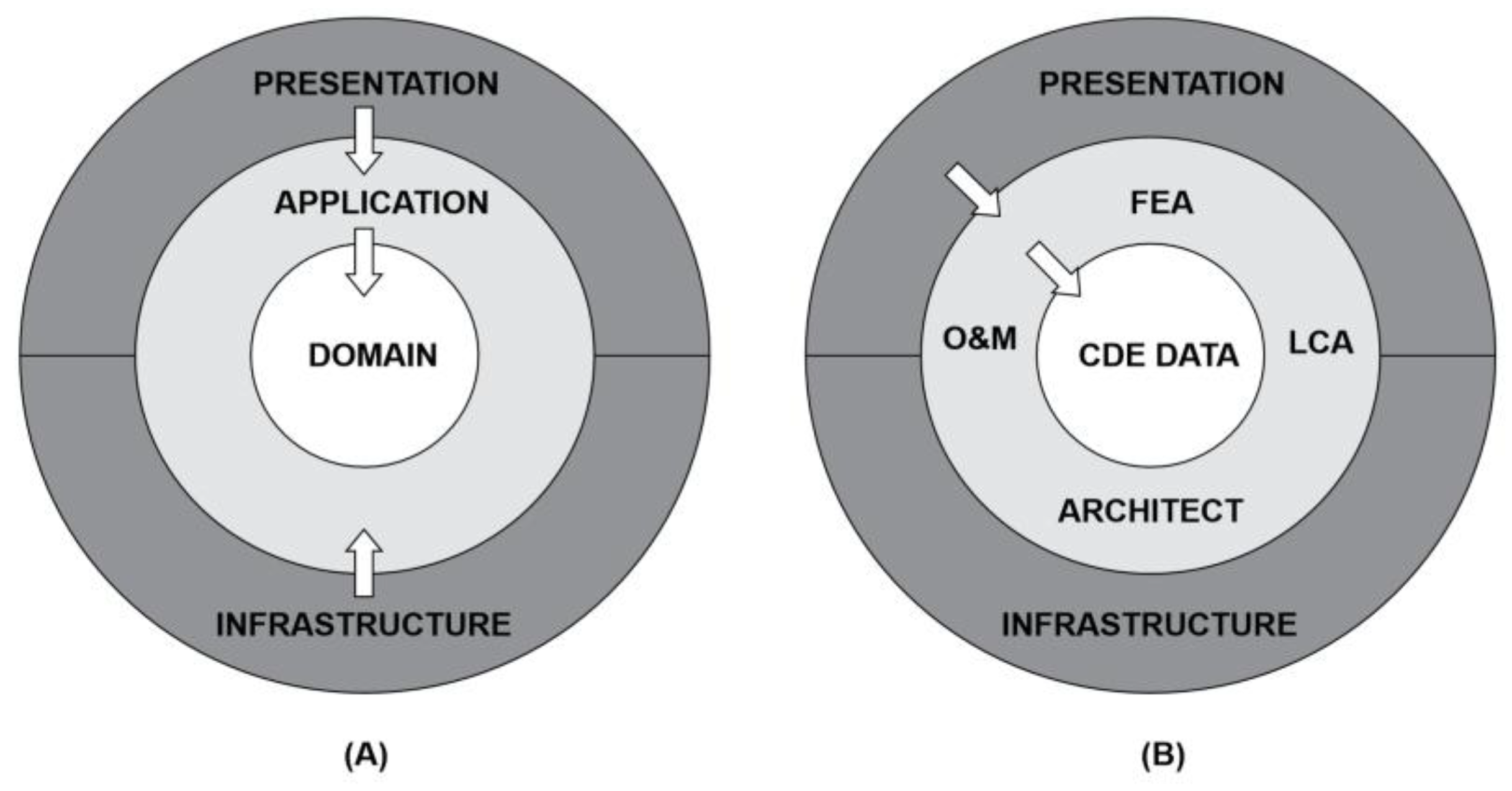
3. Proposed Framework

Figure 1 provides a roadmap for this study. A CDE framework designed to support multi-disciplinary data integration to building LCA assessments. Our approach integrates newly added data at any phase of the building’s lifetime, enabling rapid response to maintenance decisions. The framework essentially incorporates decentralized hosted data storage and microservice-based middleware, and the overall architecture has been structured into three layers:
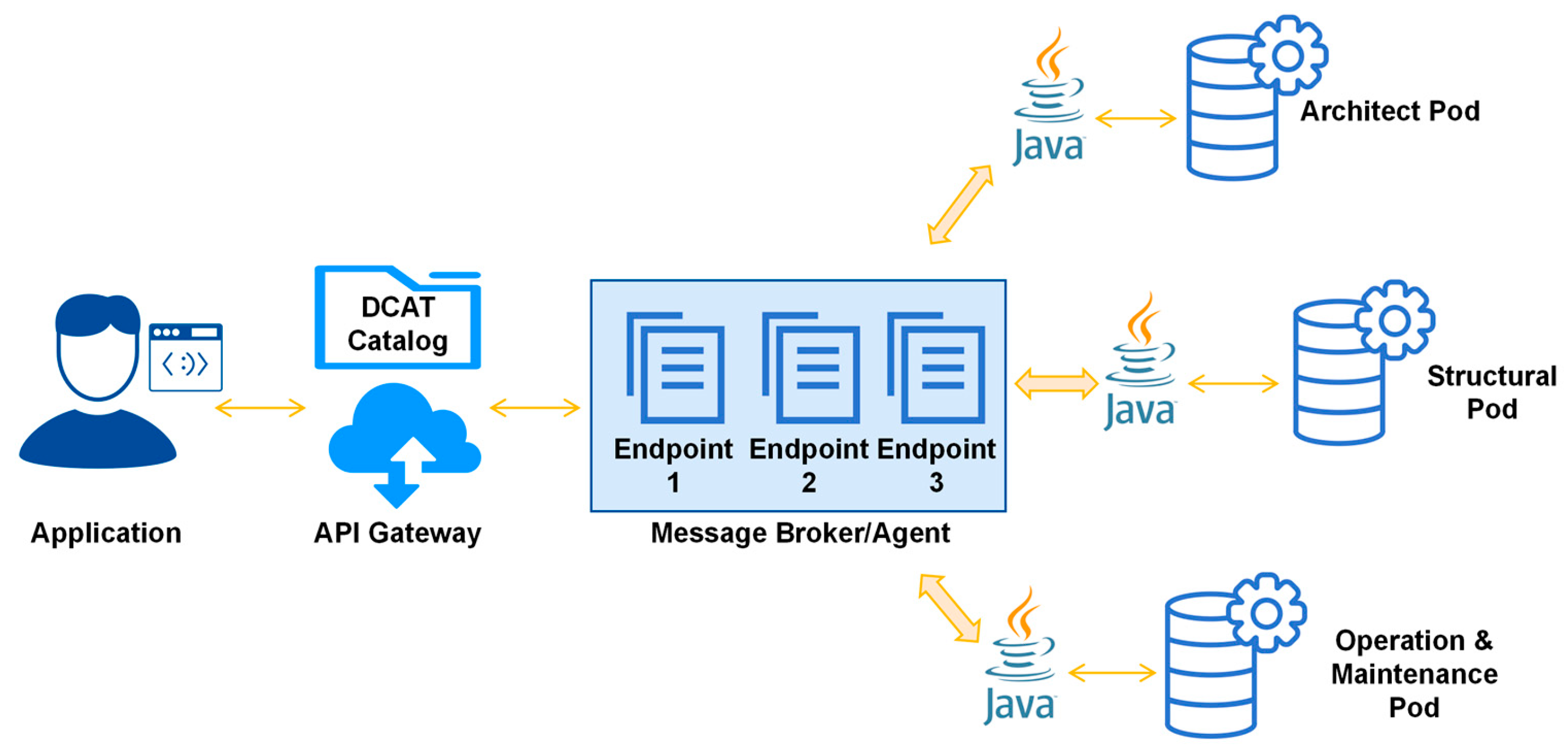
  • Application Layer. In this layer, native applications or standalone software are local clients of a decentralized hosted data storage system. e.g., the finite element analysis solver and the LCA tool.
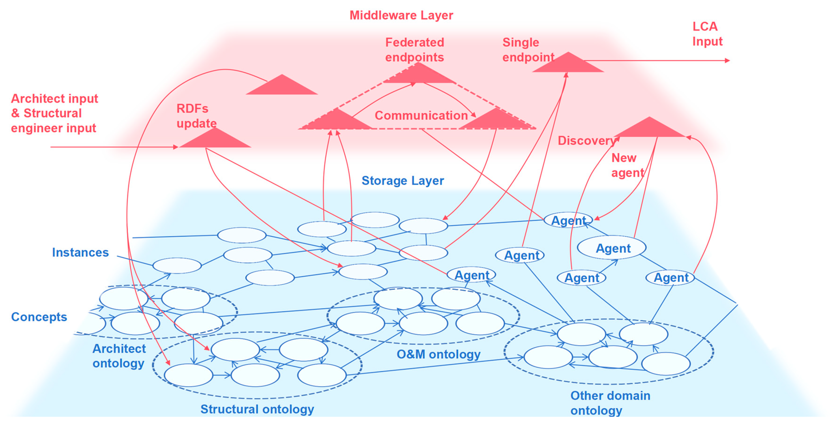
  • Middleware Layer. The middleware layer includes two types of microservices, aggregators and adapters, utilized to facilitate communication with decentral stored data and obtain inputs requested by local applications.
  • Storage Layer. This layer stores the pertinent datasets of the building LCA project, which are decentralized in disparate repositories yet adhere to RDF open data format that permits their discovery and filtering via SPARQL queries.

3.1. Application Layer: Project Scope

Scoping a project for a local client/application involves identifying a dataset of interest within a decentralized hosted data storage, e.g., “a dataset of interest” for structural resilience encompasses the response of structural components, architectural layout, and disaster consequences database. “All gymnasiums of a city” is a directory of hyperlinks, and it might be integrated within one or more broader categories, such as “city emergency facilities”, thereby providing a structured approach to accessing related asset information. When requesting (or reading) information from a client, the local application layer initially initiates a query to the project gateway. Then, the gateway responds to the project catalog to locate the other stakeholders’ repository access points. Subsequently, SPARQL queries are used to obtain further specialized datasets compatible with disciplinary applications. Convert the retrieved datasets into local application-compliant data, returning the information as HTTP responses. In this paper, we develop the microservices performed as middleware to conduct the above process (see Figure 2). There are three principal steps here: (1) Discover related endpoints of federated projects through a recursive catalog, the Data Catalog (DCAT) vocabulary [46], which serves as a gateway. (2) Traverse the project graph (i.e., hybrid RDF data from the entire asset) by endpoints to aggregate domain data from multiple discipline repositories (see Figure 3). (3) Filter the desired dataset through views and viewpoints and then give feedback to professional applications.

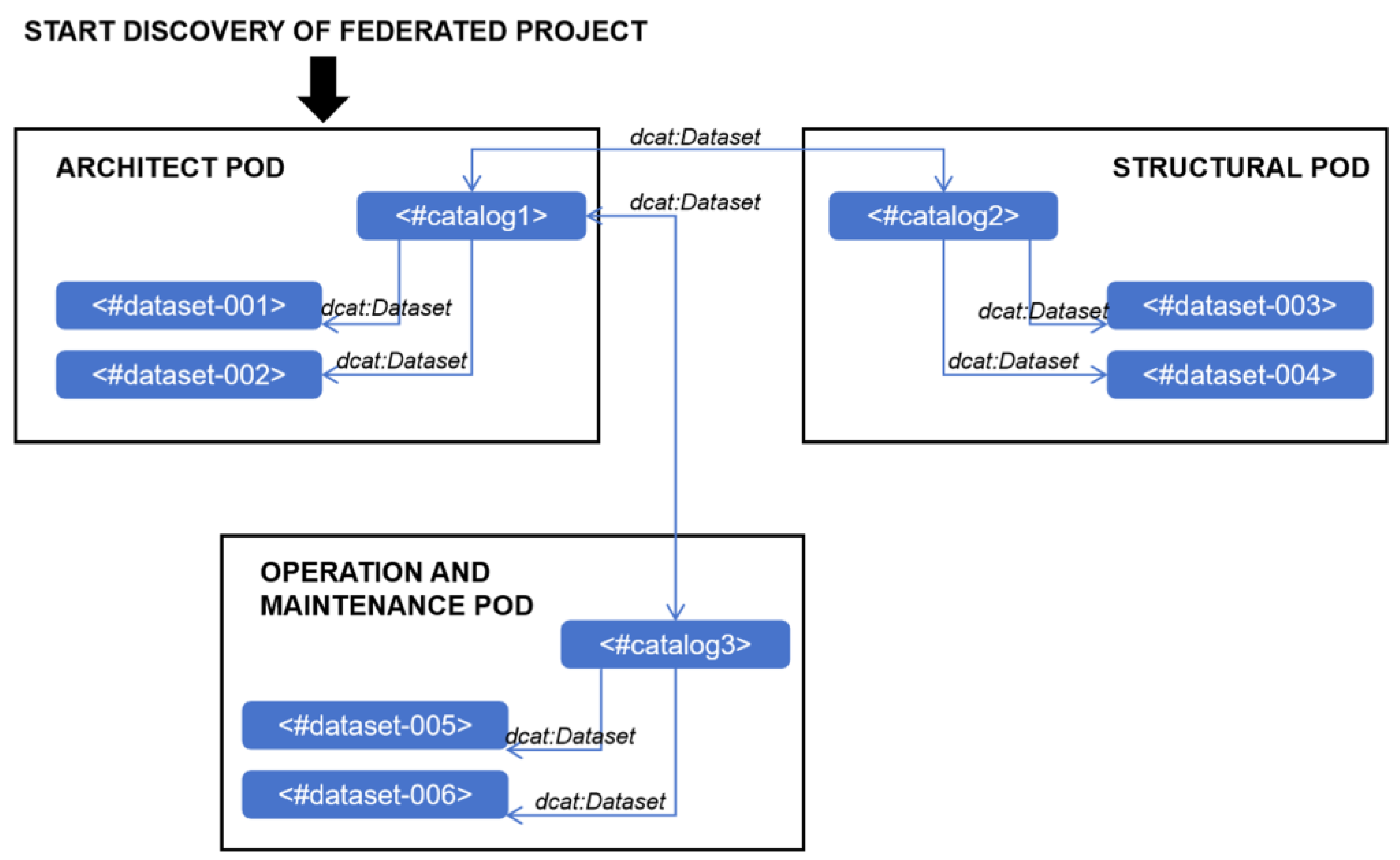
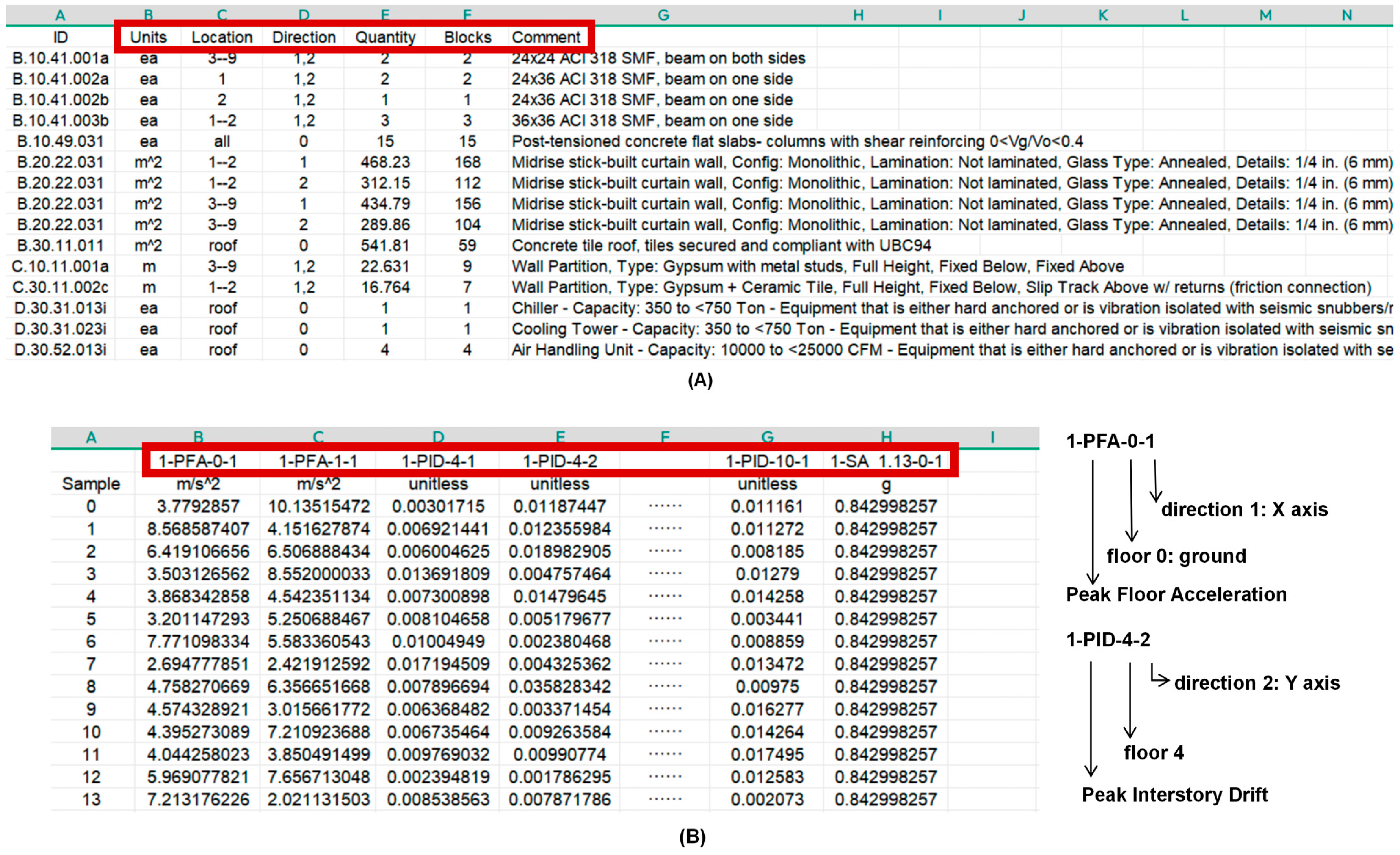
3.2. Storage Layer: Reusable Data

The pertinent datasets of the LCA project should be dealt with as follows:
  • Heterogeneous data (i.e., images, documents, models, and results) are stored in proprietary formats and subsequently annotated with metadata structured in RDF format. Once other registered endpoints of the federated project are retrieved using the DCAT vocabulary, it is possible to look up the specific dataset on a third-party repository and download the location.
  • Three repositories contain architecture, structural analysis, and hazard evaluation model datasets. The term “model” does not imply the RDF serialization of domain-specific knowledge, i.e., hard-coding of BIM information, finite element matrix, and performance-based consequence functions into RDFs. The objective is to facilitate the interoperability of data types by automatically identifying relevant datasets through metadata and enabling engineers to continue working in their preferred professional environment.
  • Project catalogs (i.e., metadata descriptions) are created based on context in communication between the local applications and the various data repositories. Subsequently, SPARQL query interfaces will employ these link sets for information retrieval and exchange.
The initial data are generated using a BIM model of a building project, forming the architectural dataset first. Figure 4 shows the process of extracting building information from Revit using the IFC-to-RDF [49] tool and IFC-to-LBD converter [50]. Following translation to RDF, the architectural dataset of buildings is machine-accessible and visible on the Internet, enabling its discovery and reorganization by queries. RDF architecture metadata encompasses component geometry, material properties, the location and orientation of building elements, equipment, environmental landscape, etc. Then, the data are stored as a set of global link sets subsequently accessed by the various modules within the workflow.

3.3. Middleware Layer: Aggregators and Adapters

3.3.1. Middleware Architecture

Clean architecture design method [51] is a low-coupling software architecture that facilitates code redevelopment in the face of functional variety. This flexibility characteristic helps integrate the CDE with other essential software tools (such as BIM software Revit 2022, OpenSeesPy 3.4.0.8, and PBEv4.1.0) throughout the project lifecycle. Clean architecture is suitable for developing middleware for distinct field participants—architects, structural engineers, and O&M staff—and is effortless in multiple middleware integration. In clean architecture, dependencies are directed inward. The infrastructure and presentation layers rely on the core layer, while the core layer remains independent of other layers. Figure 5A illustrates this inward-dependent relationship using three concentric circles. In practice, layers are unlimited as long as all dependencies consistently point towards the core layer. This flexibility allows for more complex and modular system designs while maintaining a clear separation of dependency.

3.3.2. Middleware Logic

The first stage of communication (Application layer → Middleware layer) includes the aggregator and the adapter. The interaction between native software and open Linked Data occurs through standardized or proprietary APIs, such as the BCFv3.0, the Python-compatible rdflib-7.1.4, and other RDFJS libraries [52]. In the initial phase, the aggregator establishes the project catalog, which comprises metadata descriptions, and subsequently initiates a query for each user’s database. The database responds to metadata about the project and continues traversing hyperlinks of retrieved access points of other stakeholders. Subsequently, the aggregator transmits a federated inquiry to obtain the requisite data. Finally, the adapter retrieves the discovered dataset and transforms it into the desired API-compatible format for local application.
The second stage of communication (Middleware layer → Application layer) relies on the aggregator to initiate a federated query to the decentralized datasets. In the previous communication, the application client requested the current view of the entire topic. View and viewpoint appeared in the 1970s, were further improved by Kruchten’s 4 + 1 architecture view model, and were formalized in the ISO/IEC/IEEE 42010:2011 [53], Systems and Software Engineering—Architecture description.
Consequently, the aggregator is applied to construct the latest view by querying bcfowl: TopicState, which refers to the original topic view. Afterward, a SPARQL query requests metadata utilizing the project catalog through the SPARQL endpoint API to filter project-scoped datasets. Then, the second SPARQL query is employed to gather datasets for discipline applications further. For example, an asset dataset allows consulting specific components or materials exported in XML/JSON/RDF/CSV formats. If the client utilizes discipline software with communication functions with JSON and XML files, extracting the inputs for the analysis module via our methodology is straightforward. Figure 6 illustrates the communication process between disparate workflows (i.e., reliability analysis, resilience analysis, and LCA cost estimation).

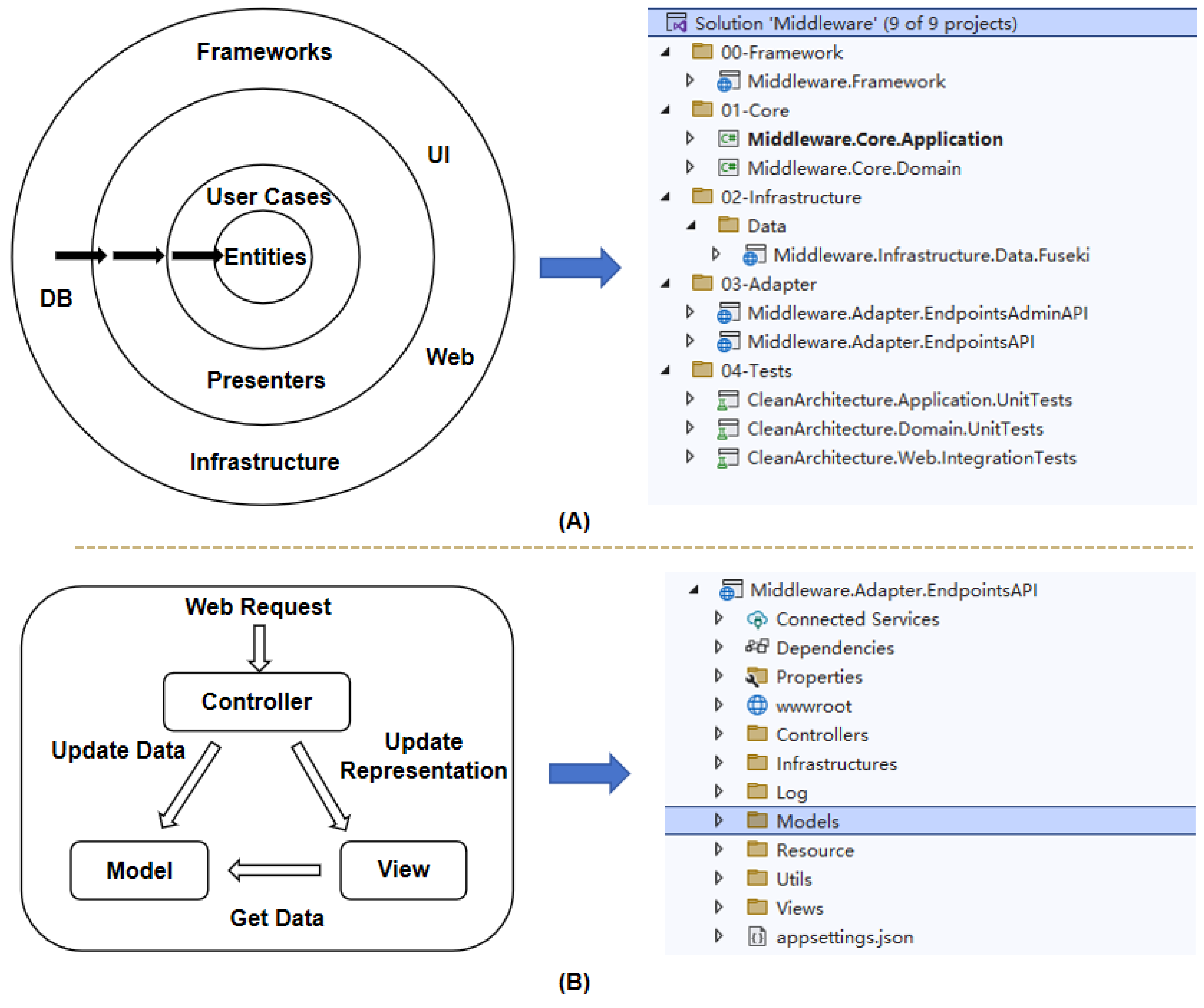
3.3.3. Middleware Programming

Using the Visual Studio development environment, based on ASP.NET 6 clean architecture templates [54], we develop microservice-based aggregators and adapters in Java code in five steps:
  • Presentation: Create two ASP.NET Web API/Blazor Service application projects: Web API and UI implementation.
  • Frameworks and Drivers: A shared class library containing external tools and frameworks. It integrates a set of reusable classes, extensions, and base classes that other layers can reference to reduce development.
  • Infrastructure: It mainly defines the database (DB technology stack). An Apache Fuseki server integrated with the TDB database provides persistent RDF storage.
  • Interface Adapters: It contains two .NET 6.0 class libraries, EndpointsAPI and EndpointsAdminAPI, which convert data from external to internal formats.
EndpointsAdminAPI is used for authentication validation if it exists needs.
EndpointsAPI includes Repositories (to interact with the database), Gateways (external interfaces for RDF data; we can choose wrapped projects such as Jena API or RDF4J), and Controllers (to handle HTTP requests).
5.
Core: It contains Application and Domain two .NET 6.0 class libraries.
The application defines services, handlers (for different databases of disciplines), validators, and various domain-oriented models.
Domain defines Entities, Constants, Enums, and Exceptions. When a single entity cannot achieve specific functions, we add domain services that can combine multiple entities within the aggregation of complex task logic. Developers realize the business capabilities of domain models according to disciplines.
The solution catalog for the entire microservice is shown in Figure 6. Figure 6A presents the clean architecture of the middleware used in aggregators and adapters, and Figure 6B shows the source code of artifact endpoints API within adapter microservice, which is crucial in interacting with the cloud-based services.

4. Case Study

4.1. Problem Definition

The proposed CDE framework is validated through a structural LCA case. The structural LCA method is a comprehensive assessment tool designed to evaluate the rapid recovery of function and long-term adaptive capacity of buildings after natural disasters (e.g., earthquakes, tsunamis, and hurricanes). Unlike the general LCA approach, which focuses on carbon footprint (ISO 14067 [55]) or environmental product declarations (EPDs) in line with EN15804 [56], structural LCA is conducted according to other international and national standards, such as FEMA P-58 [57], REDi [58], and GB/T 38591-2020 [59], which provide frameworks and guidelines for obtaining estimates of repair costs, downtime, and casualties. The widely used structural LCA tool includes PACT, PET, and Performance Based Engineering (PBE) [60], which provide robust data analysis and simulation capabilities to evaluate buildings’ performance and resilience under extreme conditions. This paper uses PBEv4.1.0 as the application layer of the proposed CDE framework to perform structural LCAs. This multi-phase process, involving various data sources, forwards assessment requests to all stakeholders for review, as illustrated in Figure 7. The steps involved are as follows:
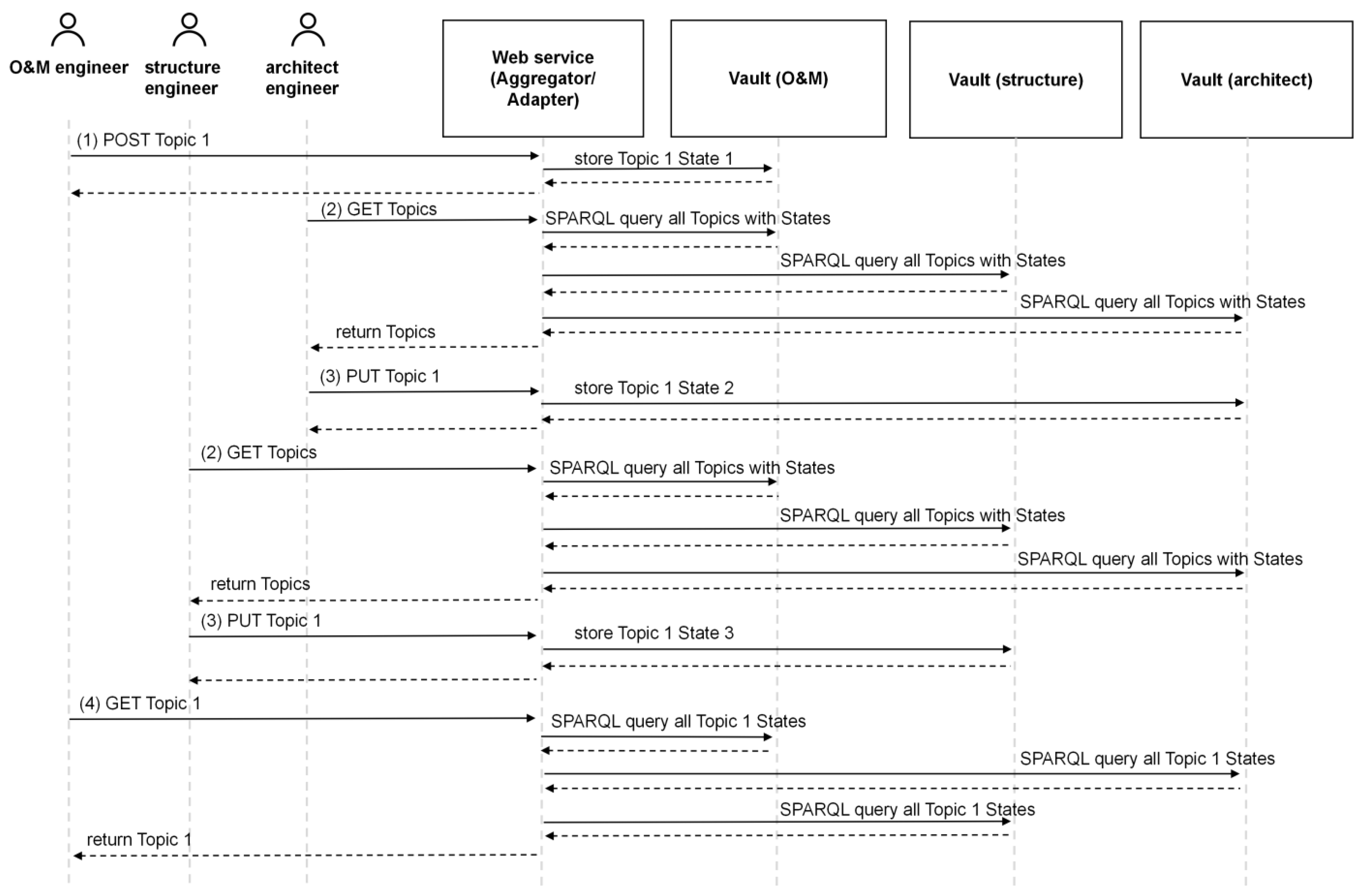
  • The O&M staff created a new topic, “LCA assessment for the building, please check the contributing components and responses”, and assigned it to the relevant reviewers. The topic contains information about the type of request and the status. The reviewers link views and viewpoints to the topic and define the building elements that point to the scenario.
  • Once the topic assignment is complete, other engineers review the tasks assigned to them:
The architect queries the RDF graph data and automatically generates a list of building components.
The structural engineer conducts a nonlinear analysis to obtain the response of each floor in both directions for each seismic intensity. Then, the Engineering Demand Parameter (EDP) will be obtained and used to infer damage states and potential cumulative losses.
3.
Update the topic status based on the architectural and structural domain engineer review results.
4.
The O&M staff verifies the topic’s status to advance the design or propose disaster-proof solutions.
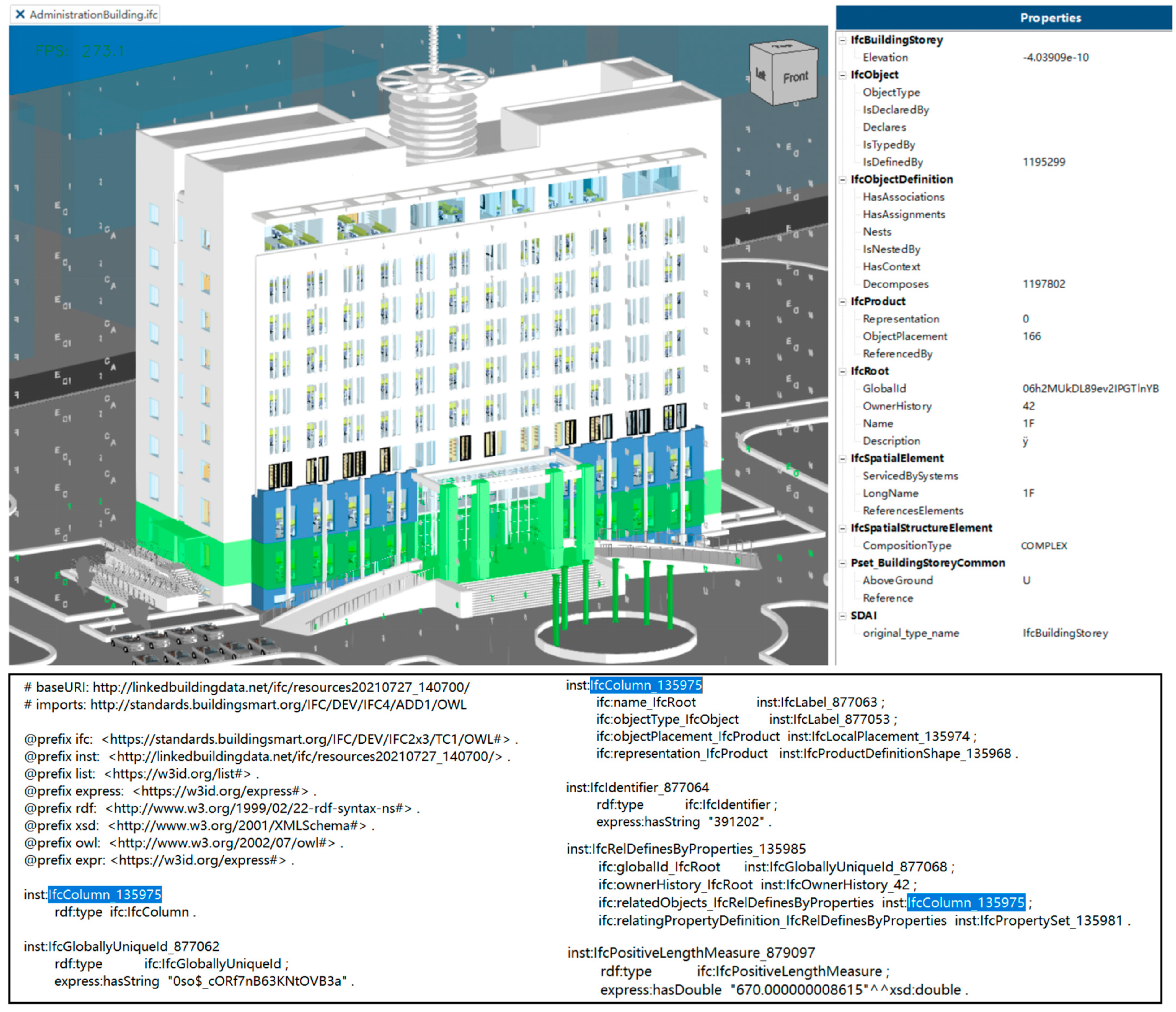
4.2. Dataset

The case study in this paper is a 10-story office building in Shenyang, China. Its structure is simple and regular, making it easy to model and analyze. The building is constructed as a special moment resisting frame (RC SMRF) structure. RC SMRF is one of the most commonly used structural systems in commercial, residential, and public buildings, and there are many similar office buildings in the local area for which LCA analysis can help to obtain representative conclusions. The selected building complies with the GB/T50011-2010 [61] seismic design code, and the seismic intensity standard for local buildings is six degrees.
The structural LCA implementation process relies on detailed architectural, construction, and operational data, including structural drawings, a list of materials, load calculations, a damage consequence database, repair costs, etc. It requires using a CDE to ensure the consistency and reliability of the data from multiple sources. The original dataset is the “AdministrationBuilding” BIM model created in Revit 2022, shown in Figure 8A and saved in IFC format. After that, we converted the RDF data using the method in Section 3.2 and uploaded them to the architect’s repository with the original dataset. Structural engineers’ modeling process for seismic nonlinear analysis is done jointly through the IFC-to-SAP 2000 interface and SAP 2000-to-OpenSeesPy code, resulting in the structural model shown in Figure 8B. Readers can find the developed structural model available in the Supplementary Materials. As an example of a structural repository, the data list in Table 1 shows the resources stored in the data container and the other resources to which it can be linked. In addition to the IFC building component information, participants link other supportive resources to the structural LCA process. It is necessary to annotate these resources and aggregate required data through the microservices middleware during the LCA execution.

4.3. Communication

Figure 9 demonstrates the communication process between the various parties outlined in Section 4.1 by the SPARQL query sequence diagram. The sequence begins with the O&M engineer. The O&M staff initiated a new topic concerning the lifecycle disaster-proof ability of the building, assigning the topic to other relevant professionals, i.e., architects and structural engineers. Listing 1 illustrates the process of the O&M engineer using RDF to store the new topic in the O&M repository, called Topic 1 State 1, and generate a metadata record, thereby ensuring this topic and its state discoverability through the SPARQL query (see Listing 1). Listing 2 shows the architect has been assigned to review Topic 1 State 1 and to check the lateral-resistant (seismic) building components in the architect’s repository. The generated Component.csv were uploaded and linked to bcfowl: TopicState. Meanwhile, Topic 1 State 1 was updated to Topic 1 State 2, including a pointer for the subsequent structural engineer’s repository (see Listing 2).
Listing 1. The original Topic and its bcfowl:TopicState initiated by the O&M engineer. This record is stored in <https://pod.o&m-engineer.com>.
<https://pod.o&m-engineer.com/Topic1> a bcfowl:Topic ;
    bcfowl:hasProject <https://pod.o&m-engineer.com/LCAAssessmentProject> .
    
<https://pod.o&m-engineer.com/TopiclState1> a bcfowl:TopicState ;
    bcfowl:hasTopic <https://pod.o&m-engineer.com/Topic1> ;
    bcfowl:hasTitle “LCA assessment for the building, please check the contributing components and responses” ;
    bcfowl:hasTopicType <https://pod.o&m-engineer.com/LCAAssessment> ;
    bcfowl:hasCreationDate “2024-06-9 18:11:25” ;
    bcfowl:hasCreationAuthor <http://localhost:3000/o&m-engineer/profile/card#me> ;
    bcfowl:hasTopicStatus <https://pod.o&m-engineer.com/LCAStatusInitial> ;
    bcfowl:hasAssignedTo <https://pod.architect-engineer.com/profile/card#me> .
Listing 2. The updated bcfowl:TopicState is <https://pod.architect.com/Topic1State2>. The new state is summarized and stored in the architect’s Pod, therefore the architect requested the end of the state and reassigned it to the structural engineer.
<https://pod.architect-engineer.com/Topic1State2> a bcfowl:TopicState ;
    bcfowl:hasTopic <https://pod.o&m-engineer.com/Topic1> ;
    bcfowl:hasCreationDate “2024-06-10 22:39:13” ;
    bcfowl:hasCreationAuthor <http://localhost:3000/architect-engineer/profile/card#me> ;
    bcfowl:hasStatus <https://pod.architect-engineer.com/ArchitectStatusEnd> ;
    bcfowl:hasAssignedTo <https://pod.structural-engineer.com/profile/card#me> .
The architect created the essential table of building assets for sharing component inputs with other professionals and uploaded the dataset to Topic 1 State 2. The table of building assets is saved as a Component.csv file, as shown in Figure 10A. Each row identifies a class of vulnerability components containing a set of influence factors, e.g., location, direction, units, component quantity in each vulnerability group, uncertainty distribution, coefficient of variation, etc. Each row’s vulnerability group has a unique ID, such as a Beam_ID “B1011.001a” in FEMA P-58. Each ID is associated with a damage list. The damage list defines the number and layout of the vulnerability components that produce damaged performances.
Structural engineers receive review tasks based on the architect’s work and perform structural dynamics simulations in a separate, trusted discipline software such as OpenSeesPy 3.4.0.8. The results of the finite element analyses are added to the URI namespace consistent with the original structural dataset and uploaded to Topic 1 State 3. Based on the results of the nonlinear analysis, the structural engineer can obtain the engineering demand parameters for each floor in each direction at each ground motion intensity and save them as an EDP.csv file. Each row of data corresponds to a one-time analysis, including event_id, type of EDP, location, and direction. Figure 10B shows partial results. Each column represents sample points for each EDP type, and multiple records are obtained by sampling numerous times. These data can fit a probability density function and a cumulative distribution function for that EDP, further determining the component’s cumulative lifecycle damage and loss. Detailed instructions for performing Monte Carlo simulations (MCS) for this seismic nonlinear problem can be found in Appendix A.
Finally, the O&M engineer initiates a federated query to the decentralized hosted architectural and structural datasets. The aggregator and adapter services traverse all States under Topic 1 in the O&M repository, aggregate the required data, and reorganize it to return to the O&M application in JSON format. This JSON file is organized to conform to the LCA assessment tool PBE inputs. Figure 11 shows the JSON input for LCA assessments in the O&M phase of the RC SMRF building used in this paper. This JSON file contains four types of parameters: (1) EDPs, (2) DSGroups, (3) DamageStates, and (4) Consequences. Each damage/loss parameter is from a built-in FEMA P-58 database and can be revised according to a change in the hazard scenario. The JSON input is automatically mapped to the vulnerability and consequence database, characterizing the resilience of the building by calculating the probabilistic capacity and consequence of various lifecycle performances. Afterward, it is up to the O&M engineers to decide whether or not to take measures (to enhance the structure).

4.4. Results

Figure 12 shows the capacity curve of the four metrics of consequence: loss (% replacement cost), repair time (days), probability of irreparable drift (%), and likelihood of collapse (%). The horizontal axis represents different earthquake intensities [g], while the vertical axis represents the probability of producing related consequences at an intensity measure. The Monto Carlo simulation process for obtaining the above statistic results is in Appendix A. The detailed statistics, such as minimum, maximum, 16th quartile, 50th quartile, 84th quartile, and probability of exceedance, are shown in Table 2. In the four charts, the light-green ranges are the upper and lower bounds of the 95% confidence interval, where the dark-green line represents the 90th percentile values of the capacity curve fitted by our case. According to the specification, the cumulative loss, predicted repair time, and unrepairable inter-story drift of the building in this paper are still within the limits. The results imply that the building satisfies structural safety and resilience under normal working conditions. Still, O&M engineers need to consider rare but severe consequence scenarios, such as large earthquakes. For example, the probability of unrepairable drift and collapse grows rapidly when seismic intensity exceeds 0.8 [g]. Next, O&M engineers can consider some hazard-mitigating methods (e.g., adding steel buckling restrained braces) for the RC SMRF building.

5. Discussion

5.1. Main Findings

Lightweight CDE implementation: By choosing appropriate tools and technology stacks, it is possible to realize a lightweight CDE solution and workflow that meets the ability of the entire project team to access each other’s work from a single source of truth without excessive complexity. For example, this paper develops a CDE for structured LCA scenarios using the bcfOWL ontology as the core data model, RESTful APIs for accessing data objects, and microservices developed with the ASP.NET 6 Clean architecture. Section 4.2 discusses multi-disciplinary data, including components, images, norms, and mechanical models, which are heterogeneous and stored in proprietary formats but annotated with RDF metadata, enabling cross-system linking and referencing through uniform resource identifiers. Figure 9, Listing 1 and Listing 2 illustrate the communication between people from different professional backgrounds (e.g., architects, structural engineers, and operations and maintenance personnel) and can query and update through standard interfaces to ensure multi-source data consistency.

5.2. Generalized to Other Domains

The CDE architecture in this paper is highly generalized. The core data model, bcfOWL, is a semantic web-based ontology specialized for data management and collaboration in BIM models. When the CDE architecture is extended to other domains, based on bcfOWL, it can develop new domain-specific ontologies, e.g., LCA ontology for environmental footprinting. When promoting the current RESTful API (BCF API, Jena API, RDFlib), only the API must be adjusted and reused according to cross-domain access between different systems. The modular ASP.NET 6 Clean architecture separates the Domain, Application, and Infrastructure layers, making the system easy to extend and maintain. Based on different business requirements, this architecture can help to develop new small standalone services to harmonize interactions with RESTful APIs, adopt RDF data-compatible frameworks and libraries, and introduce other proprietary tool interfaces.

5.3. Limitations and Future Directions

Compared to other successful CDE solutions in the construction industry, the three-layered CDE architecture developed in this paper is lightweight and versatile. For example, the Sydney Metro project used the Aconex platform to create a unified CDE, the London Crossrail project used cloud-based CDE platforms, including Autodesk BIM 360 and Bentley ProjectWise, and the Singapore Changi Airport project applied the Asite CDE platform to manage the information exchange and approvals throughout the lifecycle. While commercial CDE solutions are ready to use, the data infrastructure and cloud-based digital components are not publicly available. The workflows and templates of commercial software are complicated to modify and inconvenient for developing innovative cross-sector businesses. Therefore, two tools that are both compliant with the CDE industry-standard ISO 19650 and flexible and easily extensible—RDF metadata and cloud-based microservices—were chosen for this paper to create a personalized, open-source CDE solution. This paper’s approach is more adaptable, compatible, and cheaper for teams, especially for small corporations or research organizations that want to implement a scenario-specific CDE practice.
Of course, implementing CDE in this paper presents challenges. First, not all stakeholders are equally adept at using the chosen CDE solution. There is a considerable lack of CDE training or courses on RDF metadata and microservices architecture. At the same time, interacting with information to accommodate project scope or stakeholder needs can be pretty complex when using CDE. Users unfamiliar with advanced features such as version control, integrated communication tools, and metadata annotations may instead add to the complexity and maintenance costs of a project. Secondly, microservices allow different technology stacks to implement various services, which may benefit projects with diverse needs but also lead to more significant technical difficulties due to the maintenance of multiple tools and interfaces. Especially for CDEs integrating with traditional BIM systems, having too many tools scattered across different services may lead to lower interoperability with traditional BIM. In the future, adequate training materials or courses provided to end-users are a significant premise for effectively utilizing CDEs.
Another limitation is the problem of manual work. Even with microservices integrating information from different sources, the handover process is still semi-automatic, inefficient, and prone to mistakes. The final required multi-disciplinary data (Figure 10 and Figure 11) are still not obtained as fully automated. Addressing these difficulties may require introducing new technologies such as Artificial Intelligence and Neuro-Symbolic programming. With Natural Language Processing (NLP), AI can extract key information from different sources (e.g., design drawings, sensor data, construction logs, etc.) and store it structurally in the CDE, eliminating the tedium of manually adding RDF metadata. Neuro-Symbolic Programming [63] combines the dual benefits of deep learning and symbolic reasoning. It can extract patterns from unstructured data while following explicit business rules and constraints. It automatically learns mapping relationships between different data sources and can complete data handover from heterogeneous systems without human intervention.

6. Conclusions

In BIM-driven collaboration, a CDE is a consolidated hub for project information, ensuring a single source of truth and efficient stakeholder coordination. Commercial CDE solutions are expensive and inflexible to expand. However, the current construction industry lacks a flexible, lightweight CDE framework that can quickly adapt to different software tools and extend to a wide range of sources of information. This research proposes a novel framework to address these limitations: (1) use RDF metadata to annotate domain datasets for cross-system linking and referencing and to ensure data consistency across various platforms; (2) use microservices with standardized APIs and query languages to enable collection, integration, and reorganization of distributed multi-source data. The two tool types are technology-agnostic, resulting in a highly interoperable, adaptable, scalable CDE prototype architecture. The proposed CDE is validated by an exemplary case, i.e., structural LCA assessments, to show that consistent data communication across different disciplines is maintained. The scientific contribution of this work lies in providing a cheap and lightweight CDE alternative aligned with the norms of ISO 19650 that enhances current CDE practices. In addition, as an application case, we comprehensively introduce the implementation of a CDE framework, including the data elements, steps, stakeholders, resource distribution, and more. The summarized knowledge and experience can support other practitioners in reproducing or adjusting their CDE solutions.

Supplementary Materials

The following supporting information can be downloaded at: https://www.mdpi.com/article/10.3390/buildings15081315/s1, File S1: 3D_frame.py; File S2: openseesvispy.py; File S3: framecase.py; Figure S1: OpenSeesPy_model_image.png.

Author Contributions

Conceptualization, L.X. and H.L.; methodology, L.X.; software, L.X.; validation, L.X. and G.L.; data curation, L.X.; writing—original draft preparation, L.X.; writing—review and editing, G.L.; visualization, L.X.; supervision, G.L. and H.L.; funding acquisition, G.L. All authors have read and agreed to the published version of the manuscript.

Funding

This research is funded by the National Natural Science Foundation of China, grant No. 12372119.

Data Availability Statement

Restrictions apply to the datasets. The datasets presented in this article are not readily available because the data are part of an ongoing study that organizes manuscripts. The authors are willing to provide a minimal dataset upon request. When the author completes the defense of the doctoral degree, the datasets are available in the repository https://github.com/LiniXiang (accessed on 13 April 2025).

Conflicts of Interest

The authors declare no conflict of interest.

Appendix A. The Probability Methodological Framework of Structural LCA

The structural LCA breaks down into four analysis phases: hazard analysis, structural analysis, fragility analysis, and loss analysis, as presented by Moehle and Deierlein [64]:
λ O V ( o v ) = G O V ( o v d m ) d G D M ( d m e d p ) d G E D P ( e d p i m ) d λ I M ( i m )
In this context, intensity measure (IM) describes external excitation vectors, such as wind or earthquake. Engineering demand parameter (EDP) represents the structural response of a building to a specific hazard. Damage measure (DM) refers to the damage state or rating of structural and nonstructural components based on the reaction. Finally, a set of output variables (OV) represents the consequence metrics, usually regarding economic index or environmental impact. For a general building, engineers can calculate the probability of a component being in a damaged condition using the results of nonlinear analysis, such as the peak inter-story drift or peak floor acceleration:
P D M i = d i k = P D M i > d i k , D M i < d i ( k + 1 )
where d i k represents the discrete damage state of the quantity of interest that exceeds the specified limit value D M i , given the annual probability of occurrence of the hazard. Researchers integrate the discrete probability P ( X > x ) into the component vulnerability curve, called the exceedance frequency. Finally, calculate all cumulative losses of lifecycle hazards, such as repair time, repair costs, collapse, and irreparable drift, to provide valuable insights to designers in choosing the most resilient design.
The 10-story fourteen-bay frame in this paper was modeled as a three-dimensional structure using the OpenSeesPy 3.4.0.8 tool and nonlinear fiber elements. See Supplementary Materials for structural model files. We selected the X-direction as the main direction of seismic action. In this example, we consider the structure deterministic and only consider the uncertainties in the ground motion model. We performed Monte Carlo simulations (MCS) for this seismic nonlinear problem to obtain the distribution and values of the EDPs. This paper used a Vlacho-Papakonstantinou-Deodatis ground motion model [65], which includes three parameters: moment magnitude, closest-to-site rupture distance, and shear-wave velocity, corresponding to the random variables M, R, and V. It is assumed that all the three variables follow a lognormal distribution: the log mean of the magnitude is 7 with a log standard deviation of 1.351, the log mean of the distance is 40 km with a log standard deviation of 7.72 km, and soil velocity has a log mean of 259 m/s with a log standard deviation of 50 m/s. Stochastic ground motions are generated using the Dakota UQ engine based on the Latin Hypercube Sampling (LHS) method, with the sample set to 50 and the seed set to 633, by running a forward propagation process through the OpenSees solver to perform nonlinear time-history analysis for 50 records of sample. Probabilistic statistics are performed on the results to obtain scatter plots, probability density, and cumulative distribution curves for each EDP, such as peak floor acceleration, peak inter-story drift, etc.
The EDP responses were then imported into the PBEv4.1.0 [66]. We continued sampling using 50 records of the EDPs, applied the previously fitted lognormal distribution, and expanded the original EDP matrix to produce 1000 simulated samples. Later, we used the built-in FEMA P-58 database to evaluate structural LCA performance. The analysis code is from the publicly available document [67]. FEMA P-58 is a recognized high standard for the seismic design of buildings and contains recommended data for all member types and all damage levels. Researchers infer residual drift from peak inter-story drift, and irreparable damage occurs when the residual drift at any floor exceeds a predefined threshold. Automatic mapping to a consequence database through the PBE tool enables the calculation of key LCA metrics such as repair cost, repair time, and collapse probability. Finally, the system generates frequency and cumulative curves to assist professional technicians in making judgments.

References

  1. Angeles, K.; Patsialis, D.; Taflanidis, A.A.; Kijewski-Correa, T.L.; Buccellato, A.; Vardeman, C. Advancing the design of resilient and sustainable buildings: An integrated lifecycle analysis. J. Struct. Eng. 2021, 147, 04020341. [Google Scholar] [CrossRef]
  2. Jaskula, K.; Kifokeris, D.; Papadonikolaki, E.; Rovas, D. Common data environments in construction: State-of-the-art and challenges for practical implementation. Constr. Innov. 2024. ahead of print. [Google Scholar] [CrossRef]
  3. Bucher, D.; Hall, D. Common Data Environment within the AEC Ecosystem: Moving collaborative platforms beyond the open versus closed dichotomy. In Proceedings of the EG-ICE 2020 Proceedings: Workshop on Intelligent Computing in Engineering, Online, 1–4 July 2020; Universitätsverlag der TU Berlin: Berlin, Germany, 2020; pp. 491–500. [Google Scholar]
  4. ISO 19650-1:2018; Organization and Digitization of Information About Buildings and Civil Engineering Works, Including Building Information Modelling (BIM)—Information Management Using Building Information Modelling, Part 1: Concepts and Principles. ISO: Geneva, Switzerland, 2018. Available online: https://www.iso.org/standard/68078.html (accessed on 13 April 2025).
  5. DIN SPEC 91391-1:2019; Common Data Environments (CDE) for BIM Projects—Function Sets and Open Data Exchange Between Platforms of Different Vendors—Part 1: Components and Function Sets of a CDE; with Digital Attachment. DIN Media: Berlin, Germany, 2019. [CrossRef]
  6. NBS. National BIM Report 2020. 2020. Available online: www.thenbs.com/knowledge/national-bim-report-2019 (accessed on 13 April 2025).
  7. Patacas, J.; Dawood, N.; Kassem, M. BIM for facilities management: A framework and a common data environment using open standards. Autom. Constr. 2020, 120, 103366. [Google Scholar] [CrossRef]
  8. Senthilvel, M.; Beetz, J.; Raabe, C. Linking and Managing Heterogeneous Data Using Information Containers: Leveraging Linked Data for BIM Stage 3 CDEs (No. RWTH-2025-01088). Ph.D. Thesis, Rheinisch-Westfälische Technische Hochschule Aachen, Aachen, Germany, 2024. [Google Scholar]
  9. Kiu, M.S.; Lai, K.W.; Chia, F.C.; Wong, P.F. Blockchain integration into electronic document management (EDM) system in construction common data environment. Smart Sustain. Built Environ. 2024, 13, 117–132. [Google Scholar] [CrossRef]
  10. Valra, A.; Madeddu, D.; Chiappetti, J.; Farina, D. The BIM Management System: A Common Data Environment Using Linked Data to Support the Efficient Renovation in Buildings. Proceedings 2020, 65, 18. [Google Scholar] [CrossRef]
  11. Tao, X.; Das, M.; Liu, Y.; Cheng, J.C. Distributed common data environment using blockchain and Interplanetary File System for secure BIM-based collaborative design. Autom. Constr. 2021, 130, 103851. [Google Scholar] [CrossRef]
  12. Tao, X.; Wong, P.K.-Y.; Xu, Y.; Liu, Y.; Gong, X.; Zheng, C.; Das, M.; Cheng, J.C. Smart contract swarm and multi-branch structure for secure and efficient BIM versioning in blockchain-aided common data environment. Comput. Ind. 2023, 149, 103922. [Google Scholar] [CrossRef]
  13. Özkan, S.; Seyis, S. Identification of common data environment functions during construction phase of BIM-based projects. In Proceedings of the CIB W78-LDAC 2021, Luxembourg, 11–15 October 2021. [Google Scholar]
  14. ISO 16739-1:2024; Industry Foundation Classes (IFC) for Data Sharing in the Construction and Facility Management Industries—Part 1: Data Schema. ISO: Geneva, Switzerland, 2024.
  15. Boje, C.; Guerriero, A.; Kubicki, S.; Rezgui, Y. Towards a semantic Construction Digital Twin: Directions for future research. Autom. Constr. 2020, 114, 103179. [Google Scholar] [CrossRef]
  16. Mons, B.; Neylon, C.; Velterop, J.; Dumontier, M.; da Silva Santos, L.O.B.; Wilkinson, M.D. Cloudy, increasingly FAIR; revisiting the FAIR Data guiding principles for the European Open Science Cloud. Inf. Serv. Use 2017, 37, 49–56. [Google Scholar] [CrossRef]
  17. Park, J. Framework for Managing Multiple Common Data Environments. In Proceedings of the Construction Research Congress 2024, Des Moines, IA, USA, 20–23 March 2024; pp. 1117–1127. [Google Scholar]
  18. Schaathun, H.G.; Rutle, A. Model-driven engineering in RDF-a way to version control. Nor. IKT-Konf. Forsk. Og Utdanning 2018. Available online: https://www.ntnu.no/ojs/index.php/nikt/article/view/5384/4860 (accessed on 13 April 2025).
  19. Esser, S.; Vilgertshofer, S.; Borrmann, A. Graph-based version control for asynchronous BIM collaboration. Adv. Eng. Inform. 2022, 53, 101664. [Google Scholar] [CrossRef]
  20. Berners-Lee, T. 5-Star Deployment Scheme for Open Data. 2022. Available online: http://5stardata.info/ (accessed on 16 August 2024).
  21. Werbrouck, J.; Taelman, R.; Verborgh, R.; Pauwels, P.; Beetz, J.; Mannens, E. Pattern-based access control in a decentralised collaboration environment. In Proceedings of the 8th Linked Data in Architecture and Construction Workshop, Dublin, Ireland, 17–19 June 2020; Volume 2636, pp. 118–131. [Google Scholar]
  22. Soman, R.K.; Whyte, J.K. Codification challenges for data science in construction. J. Constr. Eng. Manag. 2020, 146, 04020072. [Google Scholar] [CrossRef]
  23. Iovescu, D.; Tudose, C. Real-Time Document Collaboration—System Architecture and Design. Appl. Sci. 2024, 14, 8356. [Google Scholar] [CrossRef]
  24. Kiviniemi, A.; Fischer, M.; Bazjanac, V. Integration of multiple product models: Ifc model servers as a potential solution. In Proceedings of the 22nd CIB-W78 Conference on Information Technology in Construction, Dresden, Germany, 19–21 July 2005. [Google Scholar]
  25. The BIM-Bot-Services. Available online: https://github.com/opensourceBIM/BIM-Bot-services/wiki (accessed on 16 August 2024).
  26. Beetz, J.; van Berlo, L.; de Laat, R.; van den Helm, P. BIMserver. org—An open source IFC model server. In Proceedings of the CIP W78 Conference, Cairo, Egypt, 16–19 November 2010. [Google Scholar]
  27. Autodesk Construction Cloud APIs. Available online: https://aps.autodesk.com/developer/overview/autodesk-construction-cloud (accessed on 16 August 2024).
  28. Vu Hoang, N.; Törmä, S. DRUMBEAT Platform—A Web of Building Data Implementation with Backlinking. In Proceedings of the eWork and eBusiness in Architecture, Engineering and Construction: ECPPM, Limassol, Cyprus, 7–9 September 2016. [Google Scholar] [CrossRef]
  29. Huyeng, T.-J.; Thiele, C.-D.; Wagner, A.; Shi, M.; Hoffmann, A.; Sprenger, W.; Rüppel, U. An approach to process geometric and semantic information as open graph-based description using a microservice architecture on the example of structural data. In Proceedings of the EG-ICE 2020 Workshop on Intelligent Computing in Engineering, Online, 1–4 July 2020. [Google Scholar] [CrossRef]
  30. Werbrouck, J.; Pauwels, P.; Beetz, J.; Mannens, E. ConSolid: A federated ecosystem for heterogeneous multi-stakeholder projects. Semant. Web 2024, 15, 429–460. [Google Scholar] [CrossRef]
  31. van Berlo, L.; Krijnen, T. Using the BIM collaboration format in a server based workflow. Procedia Environ. Sci. 2014, 22, 325–332. [Google Scholar] [CrossRef]
  32. Bakkas, J.; Bahaj, M. Generating of RDF graph from a relational database using Jena API. Int. J. Eng. Technol. 2013, 5, 1970–1975. [Google Scholar]
  33. RDFLib—A Python Library for Working with RDF. Available online: https://github.com/RDFLib/rdflib (accessed on 16 October 2024).
  34. Yijing, Z.; Xiang, M.; Yuzhou, S.; Ting, L.; Yi, Z.; Peng, L. Research on Barriers of BIM Application in Construction Enterprises——Based on Literature Review Method. J. Inf. Technol. Civ. Eng. Archit. 2019, 11, 61–65. [Google Scholar] [CrossRef]
  35. Yavan, F.; Maalek, R.; Toğan, V. Structural Optimization of Trusses in Building Information Modeling (BIM) Projects Using Visual Programming, Evolutionary Algorithms, and Life Cycle Assessment (LCA) Tools. Buildings 2024, 14, 1532. [Google Scholar] [CrossRef]
  36. Sandberg, M.; Mukkavaara, J.; Shadram, F.; Olofsson, T. Multi-disciplinary optimization of lifecycle energy and cost using a BIM-based master model. Sustainability 2019, 11, 286. [Google Scholar] [CrossRef]
  37. Bansal, V.K. Integrated framework of BIM and GIS applications to support building lifecycle: A move toward nD modeling. J. Archit. Eng. 2021, 27, 05021009. [Google Scholar] [CrossRef]
  38. Sinha, R.; Lennartsson, M.; Frostell, B. Environmental footprint assessment of building structures: A comparative study. Build. Environ. 2016, 104, 162–171. [Google Scholar] [CrossRef]
  39. Rafiq, M.Y.; Rustell, M.J. Building information modeling steered by evolutionary computing. J. Comput. Civ. Eng. 2014, 28, 05014003. [Google Scholar] [CrossRef]
  40. Boonstra, S.; van der Blom, K.; Hofmeyer, H.; Emmerich, M.T. Conceptual structural system layouts via design response grammars and evolutionary algorithms. Autom. Constr. 2020, 116, 103009. [Google Scholar] [CrossRef]
  41. De Wolf, C.; Pomponi, F.; Moncaster, A. Measuring embodied carbon dioxide equivalent of buildings: A review and critique of current industry practice. Energy Build. 2017, 140, 68–80. [Google Scholar] [CrossRef]
  42. Gavrilovic, S.; Haukaas, T. Multi-model probabilistic analysis of the lifecycle cost of buildings. Sustain. Resilient Infrastruct. 2020, 7, 313–331. [Google Scholar] [CrossRef]
  43. Frances, Y.S.E. Whole Building Life Cycle Assessment: Reference Building Structure and Strategies; American Society of Civil Engineers: Reston, VA, USA, 2018; pp. 1–80. [Google Scholar]
  44. Li, S.-D.; Xu, Z.-D. System Configuration Design of BIM Object-Oriented Database for Civil Engineering. J. Constr. Eng. Manag. 2022, 148, 04022130. [Google Scholar] [CrossRef]
  45. Poinet, P.; Stefanescu, D.; Papadonikolaki, E. Collaborative workflows and version control through open-source and distributed common data environment. In Proceedings of the International Conference on Computing in Civil and Building Engineering, São Paulo, Brazil, 18–20 August 2020; Springer International Publishing: Cham, Switzerland, 2020; pp. 228–247. [Google Scholar]
  46. Kirstein, F.; Dittwald, B.; Dutkowski, S.; Glikman, Y.; Schimmler, S.; Hauswirth, M. Linked data in the european data portal: A comprehensive platform for applying DCAT-AP. In Proceedings of the International Conference on Electronic Government, San Benedetto Del Tronto, Italy, 2–4 September 2019; Springer: Berlin/Heidelberg, Germany, 2019; pp. 192–204. [Google Scholar] [CrossRef]
  47. Werbrouck, J.; Schulz, O.; Oraskari, J.; Mannens, E.; Pauwels, P.; Beetz, J. A generic framework for federated CDEs applied to Issue Management. Adv. Eng. Inform. 2023, 58, 102136. [Google Scholar] [CrossRef]
  48. Fielding, R.; Nottingham, M.; Reschke, J. (Eds.) Hypertext Transfer Protocol—RFC 9110: HTTP Semantics; RFC Editor: Marina del Rey, CA, USA, 2022; Available online: https://www.rfc-editor.org/rfc/rfc9110.html (accessed on 13 April 2025).
  49. Oraskari, J. IFCtoRDF-Desktop: The IFCtoRDF Desktop Application, version 2.8; Zenodo: Genève, Switzerland, 2020. [Google Scholar] [CrossRef]
  50. Oraskari, J.; Bonduel, M.; McGlinn, K.; Wagner, A.; Pauwels, P.; Kukkonen, V.; Steyskaland, S.; Lehtonen, J.; Lefrançois, M.; McGibbney, L.J. IFCtoLBD: IFCtoLBD v 2.43.6. Available online: https://github.com/jyrkioraskari/IFCtoLBD (accessed on 16 August 2024).
  51. Giretti, A. Basics of Clean REST APIs. In Coding Clean, Reliable, and Safe REST APIs with ASP. NET Core 8: Develop Robust Minimal APIs with. NET 8; Apress: Berkeley, CA, USA, 2023; pp. 91–212. [Google Scholar]
  52. A Comparison of JavaScript libraries for Working with RDF. Available online: https://www.w3.org/community/rdfjs/wiki/Comparison_of_RDFJS_libraries (accessed on 13 April 2025).
  53. ISO/IEC/IEEE 42010:2022; Software, Systems and Enterprise—Architecture Description. ISO: Geneva, Switzerland, 2022.
  54. Zhou, E. ASP.NET 6 Clean Architecture Template. Available online: https://github.com/EdisonChou/CleanArchitectureTemplate (accessed on 16 August 2024).
  55. ISO 14067:2018; Greenhouse Gases—Carbon Footprint of Products—Requirements and Guidelines for Quantification. ISO: Geneva, Switzerland, 2018.
  56. EN 15804:2012+A2:2019/AC:2021; Sustainability of Construction Works e Environmental Product Declarations—Core Rules for the Product Category of Construction Products. CEN: Brussels, Belgium, 2021.
  57. FEMA. Building the Performance You Need: A Guide to State-of-the-Art Tools for Seismic Design and Assessment: FEMA P-58-7; Federal Emergency Management Agency: Washington, DC, USA, 2018. [Google Scholar]
  58. Gebelein, J.; Barnard, M.; Cochran, M.; Haselton, C.; McLellan, R.; Porter, K. Considerations for a framework of resilient structural design for earthquakes. In Proceedings of the Structural Engineers Association of California Convention (SEAOC 2017), San Diego, CA, USA, 13–15 September 2017. [Google Scholar]
  59. GB/T 38591−2020; Standard for Seismic Resilience Assessment of Buildings. Standards Press of China: Beijing, China, 2020. (In Chinese)
  60. Deierlein, G.G.; McKenna, F.; Zsarnóczay, A.; Kijewski-Correa, T.; Kareem, A.; Elhaddad, W.; Lowes, L.; Schoettler, M.J.; Govindjee, S. A Cloud-Enabled Application Framework for Simulating Regional-Scale Impacts of Natural Hazards on the Built Environment. Front. Built Environ. 2020, 6, 558706. [Google Scholar] [CrossRef]
  61. GB/T50011-2010; Seismic Design Standards for Buildings. Ministry of Housing and Urban-Rural Construction of the People’s Republic of China: Beijing, China, 2024. (In Chinese)
  62. OpenSeesPy—Version 3.4.0.5. Available online: https://github.com/zhuminjie/OpenSeesPy/tree/v3.4.0.5 (accessed on 25 March 2025).
  63. Hitzler, P.; Eberhart, A.; Ebrahimi, M.; Sarker, M.K.; Zhou, L. Neuro-symbolic artificial intelligence: The state of the art. Natl. Sci. Rev. 2022, 9, nwac035. [Google Scholar] [CrossRef]
  64. Moehle, J.; Deierlein, G.G. A framework methodology for performance-based earthquake engineering. In Proceedings of the 13th World Conference on Earthquake Engineering, WCEE, Vancouver, BC, Canada, 1–6 August 2004; Volume 679, p. 12. [Google Scholar]
  65. Vlachos, C.; Papakonstantinou, K.G.; Deodatis, G. Predictive model for site specific simulation of ground motions based on earthquake scenarios. Earthq. Eng. Struct. Dyn. 2018, 47, 195–218. [Google Scholar] [CrossRef]
  66. Zsarnoczay, A.; McKenna, F.; Gardner, M.; Gardner, M.; Wang, C.; Yi, S.-R.; Satish, A.B.; Pakzad, A.; Elhaddad, W. NHERI-SimCenter/PBE, Version 4.1.0 (v4.1.0); Zenodo: Genève, Switzerland, 2024. [Google Scholar] [CrossRef]
  67. FEMA P-58 Assessment Using External Demands. Available online: https://nheri-simcenter.github.io/PBE-Documentation/ (accessed on 25 March 2025).
Figure 1. The roadmap for this study.
Buildings 15 01315 g001
Figure 2. Local applications initiate federated queries by calling the aggregator service using Java 17 code.
Buildings 15 01315 g002
Figure 3. The discovery patterns of related datasets in decentralized hosted pods in a federated query.
Buildings 15 01315 g003
Figure 4. The reusable data from the BIM model to the IFC model and RDF metadata.
Buildings 15 01315 g004
Figure 5. (A) The basic clean architecture [49]; (B) clean architecture adapted to the middleware in this paper (microservices).
Buildings 15 01315 g005
Figure 6. (A) The microservice source code for aggregators and adapters; (B) the source code of endpoints API within adapter microservice. Endpoints API interacts with the cloud-based services.
Buildings 15 01315 g006
Figure 7. The multi-party communication of a structural LCA assessment during the O&M phase.
Buildings 15 01315 g007
Figure 8. Images of case study modeling: (A) BIM model; (B) OpenSeesPy [62] model.
Buildings 15 01315 g008
Figure 9. A sequence diagram describing the communication process between the various parties is in Section 4.1. The process begins with the O&M engineer and ends with the O&M engineer. Obtaining cross-domain data requires aggregator services and adaptor services to gather data from distributed data storage and then adapt this information to be compatible with LCA missions.
Buildings 15 01315 g009
Figure 10. (A) The list of related building assets created by architects under O&M’s topic. (B) Finite element analysis results produced by the structural engineer based on the architect’s updated Topic 1 State 2, representing the building’s response to possible hazard exposures during the O&M phase.
Buildings 15 01315 g010
Figure 11. This JSON input is a comprehensive result of multi-party queries in the O&M phase. This JSON file contains four types of damage/loss parameters: (1) EDPs, (2) DSGroups, (3) DamageStates, and (4) Consequences, where each parameter corresponds to the FEMA P-58 structural LCA method.
Buildings 15 01315 g011
Figure 12. Statistics for four lifecycle performance metrics: (A) loss (%replacement cost); (B) repair time (days); (C) probability of irreparable drift (%); (D) probability of collapse (%).
Buildings 15 01315 g012
Table 1. The data contents summary involved in the structural engineer’s repository.
ScopeCoverageContains
IFC componentMaterial CategoriesConcrete, Steel
Environmental IndicatorsThermal transmittance
Product VarietyIfcColumns, IfcBeams, IfcSlab
Load BearingsQto_ColumnBaseQuantities, Pset_ColumnCommon, Ifc_Root, Pset_ReinforcementBarPitchofColumn……
TraceabilityGeneral InformationGlobalId, OwnerHistory, Notes, and Namespace
InteroperabilityAvailable OutputsXML/JSON/RDF/CSV
Interoperable APIsRDFlib, BCF API
MetadataRDF 1.2 Schema
AccessHTTP request
ComprehensivenessSupportive ResourcesPDFs, building ontologies, the interface of external databases (FEMA P-58), OpenSeesPy models, and EDP results……
UpdateUpdate endpoints:/select-documents,/upload-documents, and/document-versions
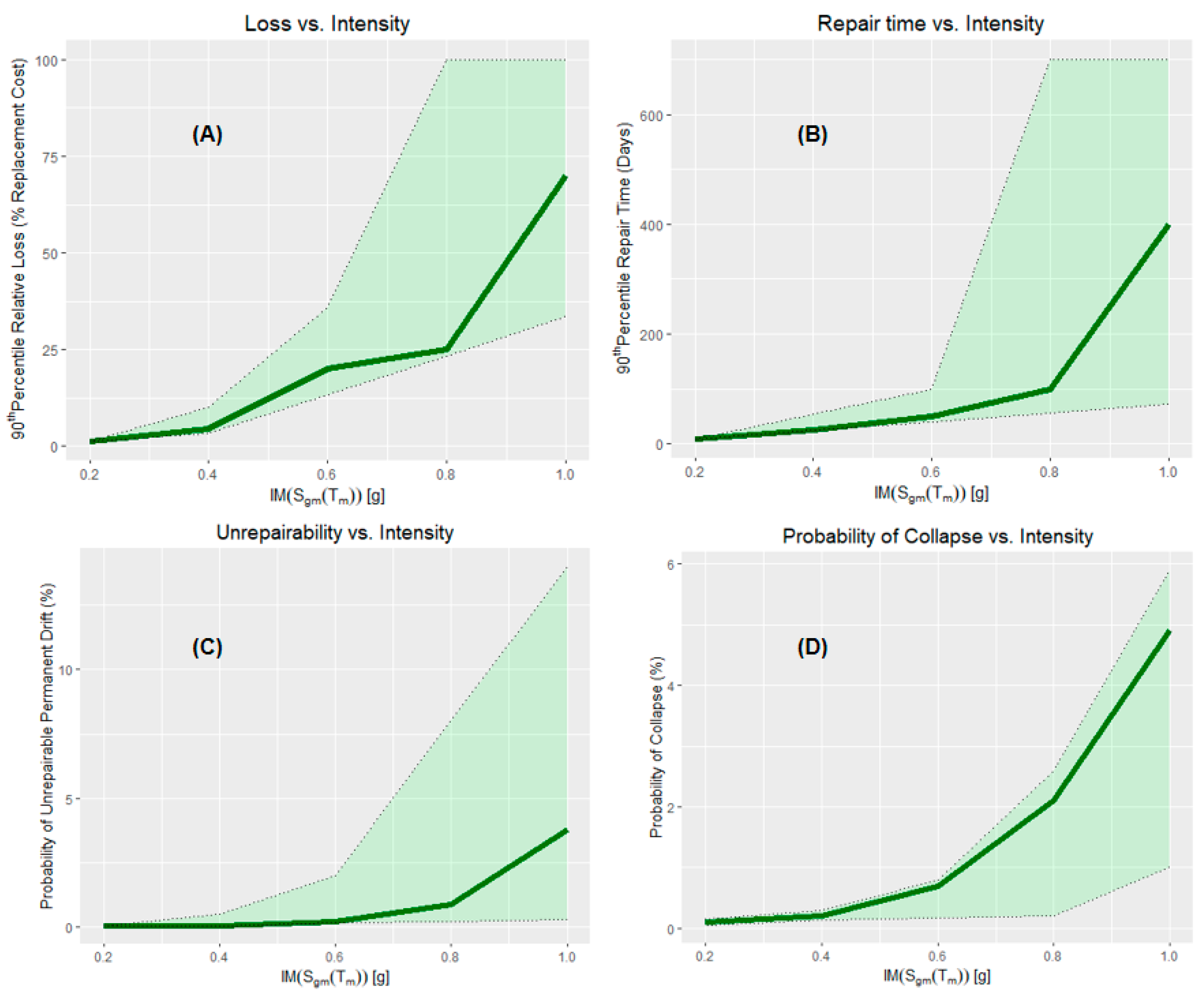
Table 2. Repair cost, repair time, embodied energy, embodied carbon, irreparable drift, and probability of collapse for RC SMRF building in Shenyang for its service life.
LCA
Performances
Probability16% Percentile50% Percentile84% PercentileConfidence Interval
Repair cost
(USD_$)
- 17.14 × 1044.85 × 1057.69 × 105[2.73 × 10⁴, 11.38 × 10⁵]
Repair time (days)-20.91302.14418.52[10.36, 719.62]
Embodied energy (MJ)-5.14 × 1052.23 × 1063.58 × 106[1.27 × 10⁵, 5.46 × 10⁶]
Embodied carbon (kg)-2.70 × 1052.28 × 1053.56 × 105[1.35 × 10⁴, 5.51 × 10⁵]
Collapse0.0507---
Irreparable drift0.0392---
1 For simplicity, the case study does not consider uncertainty factors such as component type, materials, and layouts. Researchers introduce uncertainty only in the ground motion model. For the uncertainty quantification in this paper’s seismic nonlinear problem, please refer to Appendix A.
Disclaimer/Publisher’s Note: The statements, opinions and data contained in all publications are solely those of the individual author(s) and contributor(s) and not of MDPI and/or the editor(s). MDPI and/or the editor(s) disclaim responsibility for any injury to people or property resulting from any ideas, methods, instructions or products referred to in the content.

