Article

QLCM Method for Determining the Quality Level of Circular Movement in Floor Plans of Houses and Apartments

Faculty of Civil Engineering, Transportation Engineering and Architecture, University of Maribor, 2000 Maribor, Slovenia
*
Author to whom correspondence should be addressed.
Buildings 2025, 15(3), 444; https://doi.org/10.3390/buildings15030444
Submission received: 18 December 2024 / Revised: 20 January 2025 / Accepted: 28 January 2025 / Published: 31 January 2025
(This article belongs to the Section Architectural Design, Urban Science, and Real Estate)

Abstract

This article deals with the specific spatial organization of residential buildings and highlights the advantages of ‘floor plans with circular paths’. When renovating the existing floor plans of houses or apartments, different floor plan variants can be designed that enable circular movement. Choosing the best variant is sometimes a difficult process. For this purpose, the so-called QLCM method (quality level of circular movement) was developed, which makes it possible to calculate the quality level of the adapted floor plan variants in terms of circular movement. The method covers the aspects of movement and visibility. Different path types, such as the path from room to room, door to door, door to window, and the path along the outer walls are analyzed. Different types of views such as single, multiple, and wide views are examined. Using the QLCM method, a special quality-level coefficient is calculated for each modified floor plan. The variant with the highest calculated coefficient can be selected for implementation. Based on case studies of converting three typologically different apartments/houses from non-circular to circular floor plans, the benefits in terms of enabling circular movement, increasing visual distance, and the perception of the size of the housing unit are demonstrated.

1. Introduction

The quality of housing floor plans has a direct impact on people’s quality of life and is linked to many space-related factors, such as the size of the housing unit, its orientation, its spatial configuration, the distribution of the various functions, the size and proportions of the individual rooms, and the visual perception within the unit, but also towards the outside [1,2,3]. However, one of the more important and often less considered aspects related to spatial organization concerns the ways in which people move between the spaces of a given unit, such as an apartment, including the characteristics of interior pathways and the preferences of users [4]. The configuration of paths and access to spaces can vary depending on various parameters, such as the general organization of the floor plan and, in particular, the position of doors and other openings [5,6,7].
If we consider the building as a whole, circulation is considered “a key organizing mechanism of a layout and communication space as it connects exterior and interior areas and reflects the overall spatial organization of the building” [7]. Circulation is often referred to as a pivotal component in architectural design, orchestrating the movement and flow within spaces. It is a comprehensive system that includes entry points, exits, and transitions between spaces [8]. In addition, the circulation system is often referred to as the backbone that forms the supporting structure of the building [2,9,10]. According to Schittich [11], “circulation is considered one of the most influential components of a design”. This is not merely about the stairs and corridors, which are perhaps the most important circulation areas of a building, but also about the space itself, which is used for circulation [11]. The latter becomes even more important when it comes to individual residential units (either family homes or apartments) [12].
In this context, this article focuses on the specific spatial organization of floor plans in residential buildings with regard to movement and highlights the characteristics, advantages, and also disadvantages of the so-called ‘floor plans with circular paths’. The principles of ‘circular floor plans’ (alternative formulation) were frequently applied in both traditional and contemporary architectural design practice, including in the design of houses or apartments [13]. However, there are not many research studies that empirically demonstrate the strengths (or weaknesses) of such concepts, especially when it comes to movement paths within individual housing units. The movement path is described as a way in which movement can occur and describes the change in physical location, i.e., from place to place. On the other hand, circular movement does not mean moving in circles (although this is sometimes possible) but moving without obstacles or following a course that leads back to the starting point. This article examines the advantages of floor plans with an inner circular path compared to other non-circular ones.

1.1. Circular Path in Floor Plans

“Floor plans often reflect the interpretation of a certain notion of living, which can be expressed in the internal organization, in the opening and closing of rooms, in the connection and grouping of rooms, in the connection or isolation of functions, and, last but not least, in paths and sightlines” [13]. The latter two aspects are of great importance in the context of floor plans with circular paths, which emphasize the connection between spaces and optimize internal routing. According to the ‘Floor plan manual’ [13], the implementation of these principles creates the most functional and spatial relationships between different spaces, where each room can be reached via two or more paths. The multitude of possible paths allows the user to experience the house from ever new perspectives and makes it appear more diverse than it actually is.
The importance of interconnecting rooms is also explicitly mentioned in Alexander’s Pattern language [2] in the pattern ‘The flow through rooms’. There, it is emphasized that “the movement between rooms is as important as the rooms themselves”, which has a great influence on social interaction in the rooms. It is also said that generous circulation allows everyone’s instinct and intuition full play, while ungenerous circulation inhibits it. The circulation path is called a loop, which runs through all the important spaces and gives the feeling of generosity or spaciousness. In such a loop, it is always possible to walk in different directions or continuously move in ‘circles’. This provides the generosity of movement that connects the rooms [2] and consequently affects social relationships [14].
In order to create meaningful connections between rooms, it is important to understand that movement within the housing unit/apartment has different purposes [15]. These include the following:
  • Functional aspects (daily tasks such as cleaning the apartment, access to people in the rooms, closing windows due to drafts…);
  • Safety aspects (evacuation in case of fire or other threat, visual control of the space…);
  • Comfort aspects (such as relaxed and unhindered movement, dancing, children playing, walking around the apartment, thinking while walking, walking dogs…).
Movement can be associated with absolutely necessary activities (such as access to the kitchen to cook), but also with optional activities (such as a walk around the apartment)—here, the parallel is drawn with Gehl’s study ‘People on foot’ [16]. The type of movement in a particular house/apartment depends on the configuration of the floor plan. In this respect, the different floor plan typologies that have evolved over time are based on different concepts of spatial organization that also reflect different cultural dimensions and the complexity of human habitation [
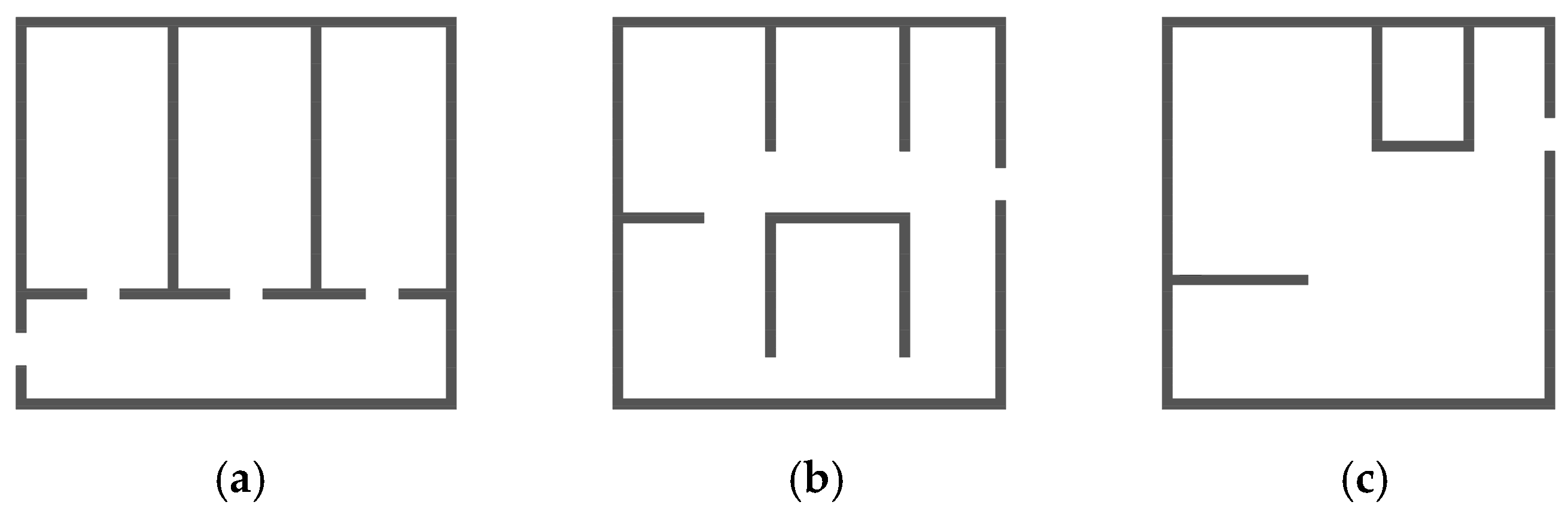
12]. For example, if we look at three basic contemporary floor plan typologies, such as a corridor/hall floor plan, a floor plan with a circular path, or a continuous floor plan, they show different types of access between rooms and allow different ways of moving around the space (Figure 1). The difference lies in the way the rooms are connected to each other. In the corridor type, each room is accessed from the corridor, which serves as a central communication point. In this case, the rooms are independently accessible and completely enclosed [13]. In comparison, with a continuous floor plan, the room boundaries are reduced to a few walls, and the individual rooms always relate to the entire space, which allows for greater spatial dynamics (the case of lofts). A floor plan with a circular path lies to a certain extent between these two extremes as it creates a more spatial connection between the rooms than the corridor type, but, at the same time, it can also maintain the room’s function as an enclosed space (by simply closing the door).
Floor plans with circular paths as a typology are special in that, at least in parts of the house or apartment, even if not entirely, circular movement can be created as a continuous flow. In practice, the spatial composition of individual rooms and the position of the openings are such that circular movements between rooms, around rooms, or around other architectural elements, such as walls, cupboards, and other furniture elements within the housing unit, are possible [17]. Characteristic examples of a circular floor plan design are houses or apartments with a central core (Figure 2a), usually containing service areas such as a kitchen, bathroom, storage room, or even a staircase condensed into the central core, so that the remaining living space allows circular movement around the core while providing longer sightlines and the perception of an enlarged dwelling [18]. Another way to construct a circular floor plan is to arrange the rooms in such a way that they have more openings than are necessary for access (
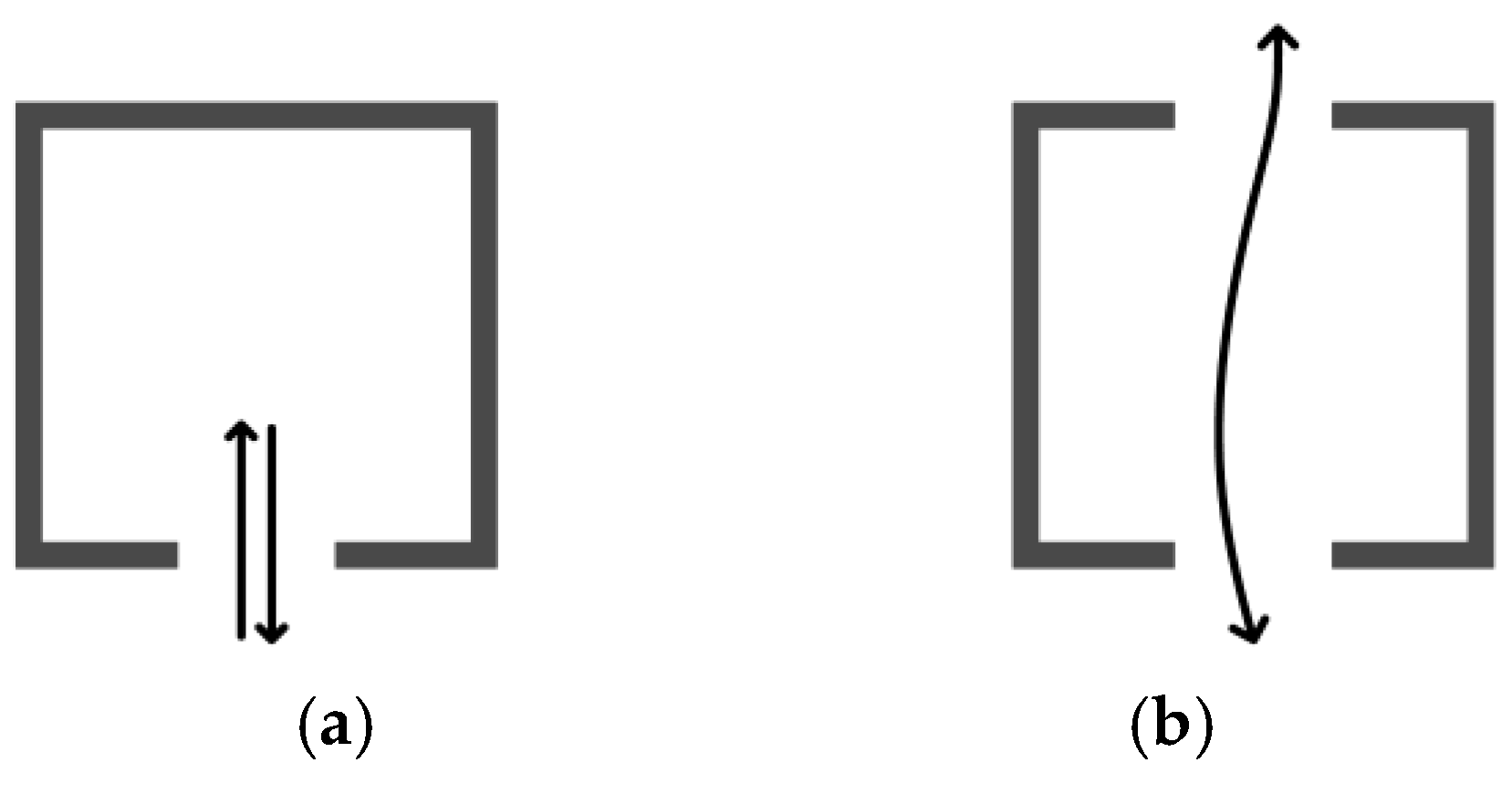
Figure 2b). This gives us more possibilities to choose the way to the room and also the direction of access. The extent to which we set up circular movement depends on the needs and possibilities, the size of the home, the question of privacy, and, last but not least, the personal preferences of the users. If the passage is defined by a door, it can also be selectively opened, closed, or locked so that the passageway can be regulated over time according to the specific needs of the users [13,19] (for example, a cupboard can be placed in front of the door when the passage is not in use, or they can be temporarily hidden). If you install more than one door/opening in a room, the question of their positioning arises—where should they be placed so that they do not interfere with each other? In architectural practice, we find that they are often placed axially—in several consecutive rooms [20]. Another approach is to place doors/openings as far away from the existing door as possible, depending on the spatial possibilities. Examples of circular designs also show the placement of secondary doors/openings close to or next to the outer walls of the building [21]; above all, the actual position should always be contextual.
The concept of circularity can also be applied to other floor plan typologies, e.g., in the case of a renovation where a floor plan could be adapted with a different circular communication scheme. Circularity can also be created in larger rooms by placing furniture and appliances in such a way that circulation around them is possible.
In terms of social impact, this typology creates more opportunities for interaction between users (between residents themselves and/or between visitors and residents), which can be seen as a good thing if it is desired; otherwise, it can also lead to conflict. How integrated (accessible) or segregated individual spaces within the home should be often depends on specific cultural backgrounds and social circumstances/norms and should be left to the user. However, integration is seen as the key through which we can understand the social context of architecture and show how buildings and places function on a collective level. This applies to both buildings and individual spaces within a building [12]. Furthermore, according to Hanson [12], space organized for social purposes should be seen neither as purely continuous nor as purely bounded but as a transformation of the spatial continuum through a system of boundaries and permeabilities into an effective space organized for human purposes. This statement was based on an investigation within the framework of the ‘Social logic of space’ [14], in which elementary buildings were defined as closed or open cells (the open segment of space can be traversed, while the closed cell is considered a dead end) (Figure 3).
A similar concept is also explained by Jay Appleton’s Prospect refugee theory, also known as Habitat theory. This states that human environmental preferences are attuned to the search for spaces that provide a balance between prospect and enclosure [22]. Although the work focuses primarily on outdoor spaces, it has also been extended to indoor spaces. An example of this is Hildebrand’s analysis of Frank Lloyd Wright’s architecture, in which he argues that the experience of moving through an environment is crucial to shaping a person’s emotional state [23]. If the path one follows has the right balance between vista and enclosure, then the experience is psychologically calming or uplifting. This also emphasizes the fundamental connection between the path of movement and the visual dimension.
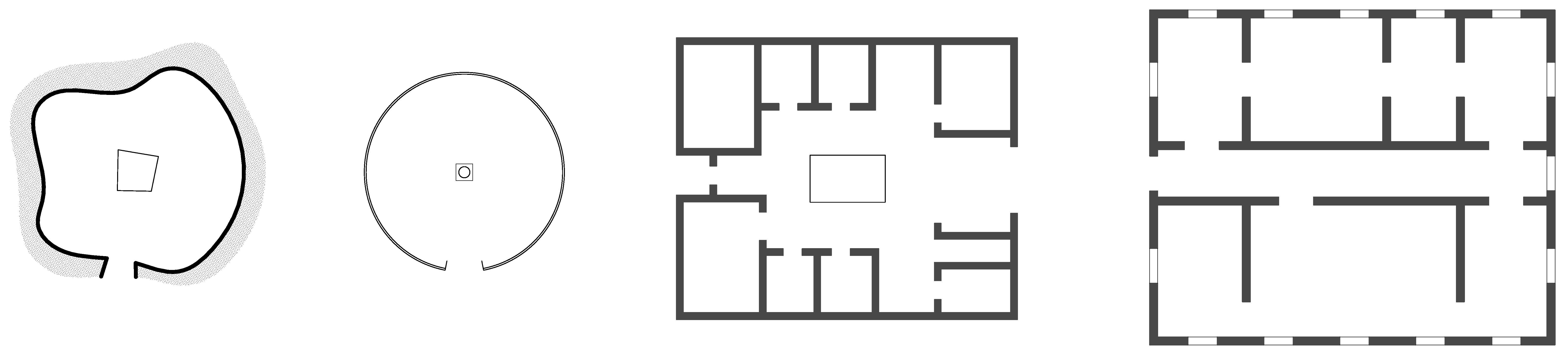
The general significance and presence of the typology discussed here can be seen from the fact that its origins can already be found in the organization of dwellings in the early history of human settlements. Simple building structures made it possible to move around the fire in the center of the room (for example, the Neolithic village of Skara Brae—Figure 4a). Circular paths were often inherent to the building form and can be found as an architectural archetype in vernacular architecture all over the world. The internal organization of nomadic yurts [12] allowed for circular movement around the central heart (Figure 4b). Roman atrium houses had an atrium in the center (Figure 4c), around which rooms were arranged (as in the House of the Faun). The circular movement in these houses focused on the atrium and formed a symbolic and functional center. Traditional Japanese houses were often organized around the atrium or main tearoom and connected by sliding doors that allowed flexible movement through the rooms. Renaissance villas were often planned to consist of interconnected rooms (Figure 4d) that allowed circulation (as in the case of the Villa Farnese). An enfilade, a series of formally aligned rooms, was common in the 18th and 19th centuries in palaces but also in public buildings and allowed next to movement also long sightlines through successive rooms [24]. This way of connecting rooms can still be found on a large scale in middle-class houses and apartment buildings at the beginning of the 20th century in Europe, until individualization (separate rooms with individual access) and specialization according to function began to be reflected more strongly in the design of floor plans [20]. Nevertheless, many influential residential buildings were planned according to this principle in modern times (Casa Batllo, Villa Savoye, Steinhaus,…) [24]. This also includes experimental houses such as the modernist Bailey house CSH N21 [25]. On the other hand, the principles were also applied in floor plans of single-family houses with a more open and unconventional design as well as in multi-story apartment buildings [21] and even in small units of social housing (such as ‘Roške stolpnice’ residential towers) [18]. These and other examples show that this typology has been implemented not only throughout the history of human settlement but also in different scales and design variations.
Research on floor plans with circular paths is relatively modestly represented in the academic literature, although research on the quality criteria for floor plans in general is much stronger in residential architecture [26,27,28], including the topic of circulation as a concept of movement. Basic circulation diagrams depicting human movement on architectural plans were already used as a method by Viollet-le-Duc in the second half of the 19th century, followed by Kerr and others [20,29]. In the paper Intimate circulation, Emmons describes how the flow diagram method used by architects was instrumental in envisioning what became a system of movement, which was isolated from the inhabited space but established schematic order of the house [20].
Circulation paths were often represented using a graph structure and a visualization based on abstract ‘graph theory’. Such an approach has been implemented in many applications and was primarily based on the ‘space syntax’ approach—e.g., in the study of Palladian villas [19]. The space syntax theory of Bill Hillier et al. is still of great relevance today in understanding the impact of spatial configurations on the facilitation of social encounters [14,30,31]. Two of the most common techniques are ‘convex spatial analysis’, which provides a specific insight into the spatial and social properties of rooms in a plan, and ‘visibility graphs’, which are used to explore spatio-visual properties of locations in a plan [19]. In the study on the space syntax of Bafna, an application for analyzing the relationships between spatial units within houses was discussed [30].
The spatial analysis method was also used in the study by Natapov et al., who investigated how the typology of building circulation is related to human orientation [7]. The article introduces three types of building circulation types and tests them on a complex building floor plan. Another article on building circulation investigates how building circulation can be optimized using the Indoor Walkability Index within BIM (as a parallel to the Walkability Index for pedestrians) by measuring factors such as distance, simplicity, and accessibility to solve complex circulation problems and support decision making in planning, particularly in building remodeling [6]. The methodology uses computational data derived from the given BIM models. In a study on the preferences of floor plans of medium-sized apartments in China, the authors looked for quantitative parameters reflecting the spatial relationships between different apartments, including the measurement of walking distances between individual spaces of the apartment. The study also included view-related aspects in the comfort assessment, such as the notion of sight interruption; the actual distances between north and south windows were measured in relation to ventilation. In addition, a questionnaire survey was carried out in which respondents were asked to choose between different floor plans according to their own preferences [13]. An early example of studies on the distances a housewife has to cover unnecessarily due to functional relationships in the kitchen was published in 1913 by Frederick in the book on rational housekeeping entitled ‘Efficiency studies in home management’. It served as the basis for the development of compact floor plans, not only for the kitchen but also for entire houses and apartments [11,32].
There is also a spectrum of research that covers technologically advanced approaches, such as computational and mathematical analysis of the spatio-visual properties of paths through houses using the so-called ‘isovist method’ [23], as in the analysis of Frank Loyd Wright’s houses. Another study on circulation paths via virtual environments and simulations is based on accurate 3D models of the environments (e.g., through 3D point clouds) [33]. Spatial navigation in immersive virtual environments can also be explored using an agent-based approach in a BIM environment or as a gamification process [34]. Another study targeted the particular problem of path planning for 3D indoor spaces, relying on the so-called IFC (Industry Foundation Class) building models, which present an upgrade to BIM technology [35]. A methodology has even been developed that translates sketched, data-driven spatial requirements into 3D building components within BIM to improve stakeholder spatial understanding and enable an analysis of building performance, etc., during the initial design stages [36]. Communication paths are not only important to navigate people in indoor spaces but might also gain importance for delivery robots or domestic help robots, for example. This has been studied in research on planning the path of a mobile robot that needs to transport and deliver small packages within a multi-story building. A navigation tree was used to plan the route of a mobile robot and estimate the total length of a delivery route (including nodes, segments, and trajectories) [37].
Generative design methods are also gaining ground. They are able to generate a large number of potential solutions for architectural floor plans [38], as in a study in which the automated layout planning of over 2500 different apartment designs was used to evaluate the flexibility of a structural scheme [39]; however, none of them appear to have been designed according to the principle of a circular floor plan. Ko et al. describe advances in graph-based approaches, e.g., with graph neural networks (GNNs), which allow models to be trained on data sets organized in the form of graphs and quickly generate very realistic floor plans, improving efficiency in generating a large number of floor plan variants [40]. Advances in artificial intelligence and machine learning offer the opportunity to advance architectural spatial layout planning and avoid constraints and an iterative and labor-intensive process. Computer-aided support in the form of automated layout planning is already paving the way to create new perspectives and methods for user-centered design [40,41].
In this context, and despite technological progress, a better understanding of the quality criteria of architectural spatial layout planning, as well as human needs and society is required, if we are to follow Alexander’s thought that buildings only feel right for the people in them when the physical spaces (defined by columns, walls, and ceilings) are congruent with the social space (defined by activities and human groups), as defined in the pattern ‘Structure follows social spaces’ [2].
In order to better understand the typology presented, we show some potential advantages and also disadvantages. The potential advantages of floor plans with circular paths are as follows:
  • Improved flow of movement (multiple entrances to rooms allow for a circular flow that creates a seamless connection between rooms);
  • Multifunctionality of spaces (spaces are often multifunctional, blurring the boundaries between circulation and living areas; corridors lose their exclusive function of providing access to spaces and become part of a larger, connected area) [2];
  • Versatility and spatial quality (circular paths improve versatility, spatial quality, and visual impact; extending views as seen in the enfilade concept improves spatial perception and esthetic quality);
  • Perceived spaciousness (circular movement patterns can improve the perception of spaciousness in small apartments against a backdrop of rising house prices);
  • Flexibility in redesigning floor plans (interconnected spaces can provide greater flexibility in redesigning apartment floor plans);
  • Design reinterpretations (modern reinterpretations of traditional or unattractive floor plans).
Possible disadvantages of floor plans with a circular path are as follows:
  • Reduction in usable space (additional doors and openings can reduce the available wall space for furniture placement) [13];
  • Impact on privacy (creating passageways between rooms can undermine privacy) [20];
  • Security concerns (numerous openings and connections can raise security concerns as they can affect the clarity and control of the space);
  • Potential orientation issues (circular floor plans can sometimes compromise clarity and ease of orientation, especially in larger homes);
  • Technical challenges (air conditioning, ventilation, and other technical systems may require more complex solutions to enable an open, connected design);
  • Personal preferences (circular layouts may not suit everyone’s preferences or lifestyle, as some people prefer more compartmentalized spaces) [20].

1.2. Aims of This Study

The design of spatial configuration, i.e., the search for a satisfactory arrangement of functional elements considering certain objectives and constraints, is required at almost every scale of architectural practice. This task is complex, considers multiple criteria, and is often poorly defined [
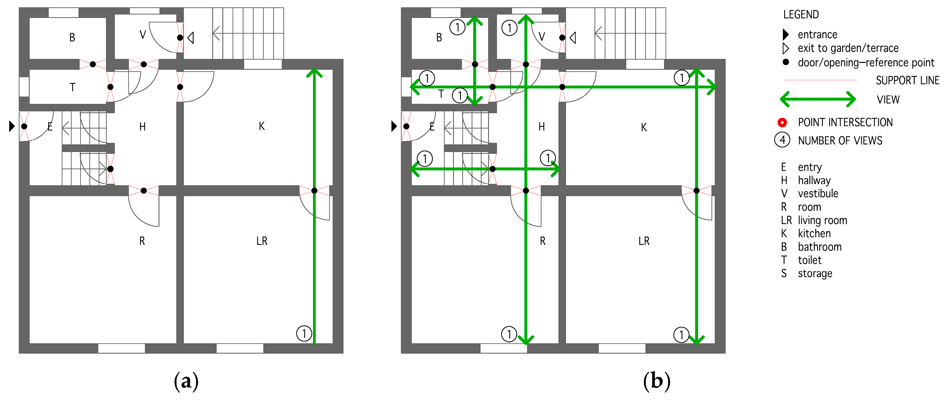
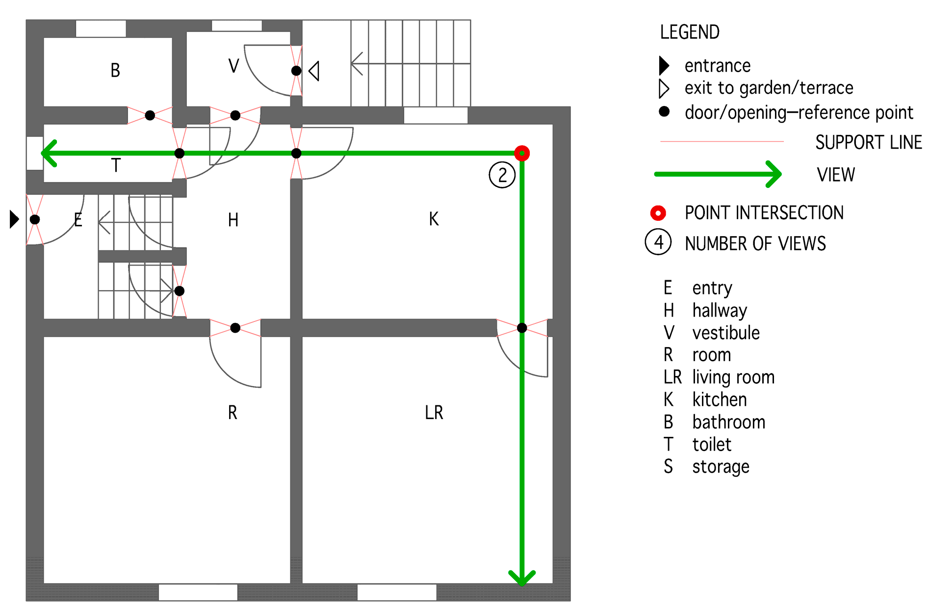
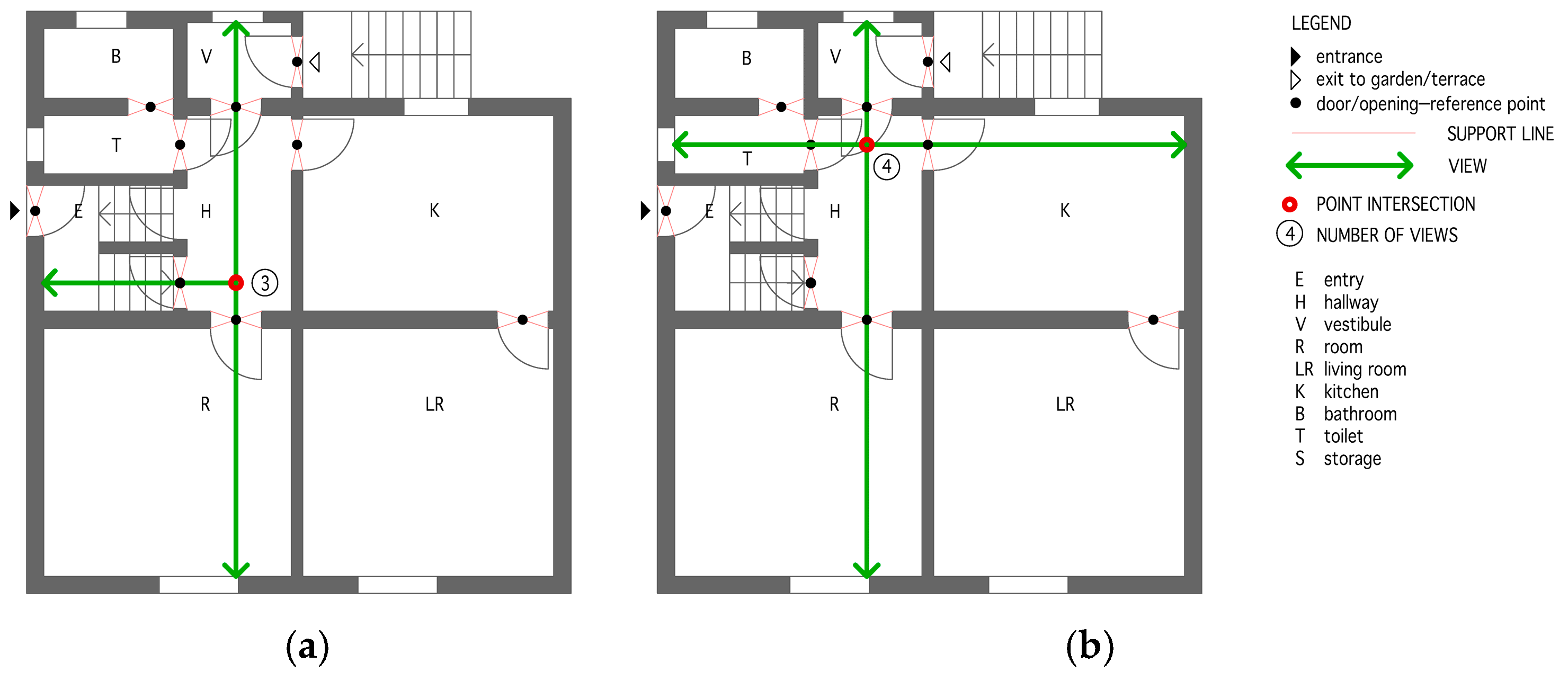
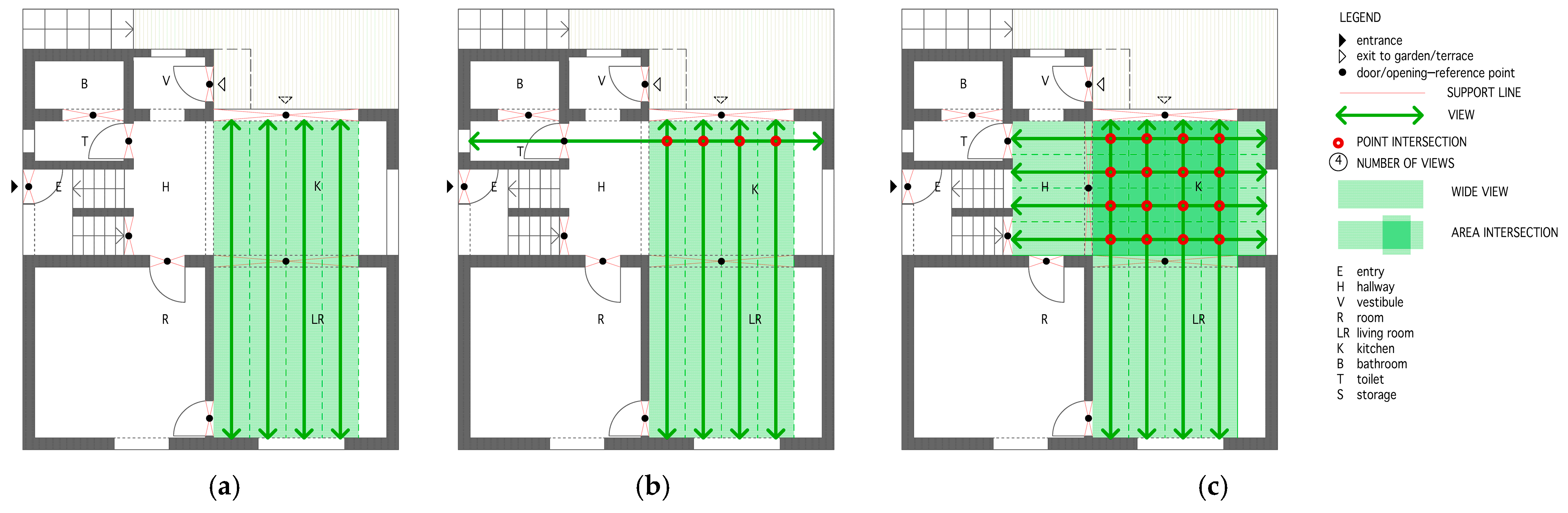
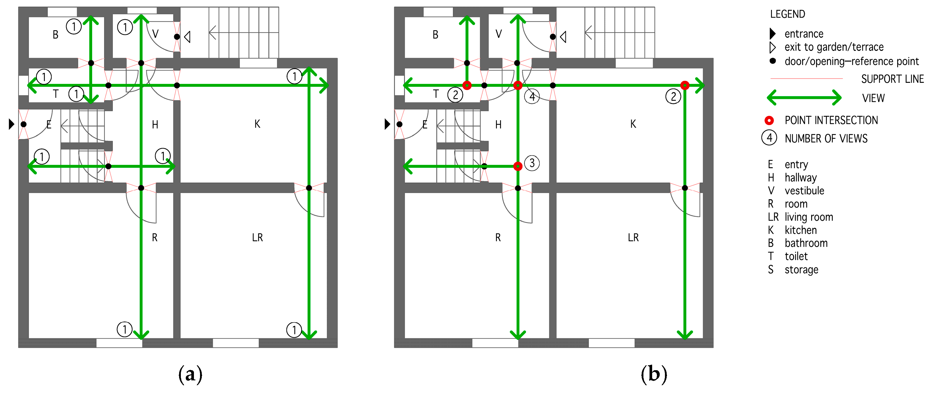
7]. In this context and despite the technological advances already mentioned, there is still no available method to measure the benefits of floor plans with circular paths while incorporating the measurement of visual aspects defined mainly by the length and number of views, simultaneously introducing the concept of single, multiple, and wide views.
This study addresses the theme of floor plans that allow circular movement between spaces with a corresponding visual impact within the housing units and defines the parameters for their evaluation, which directly affect the quality of housing.
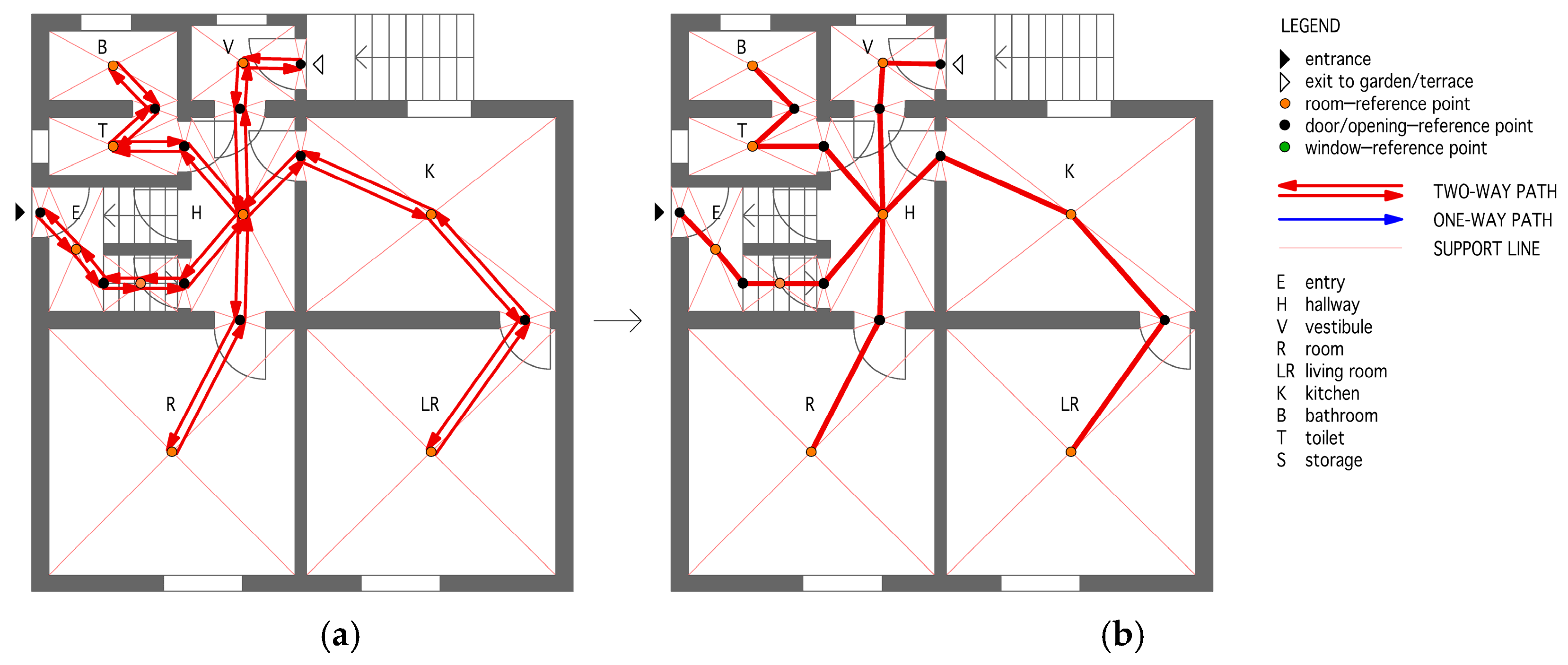
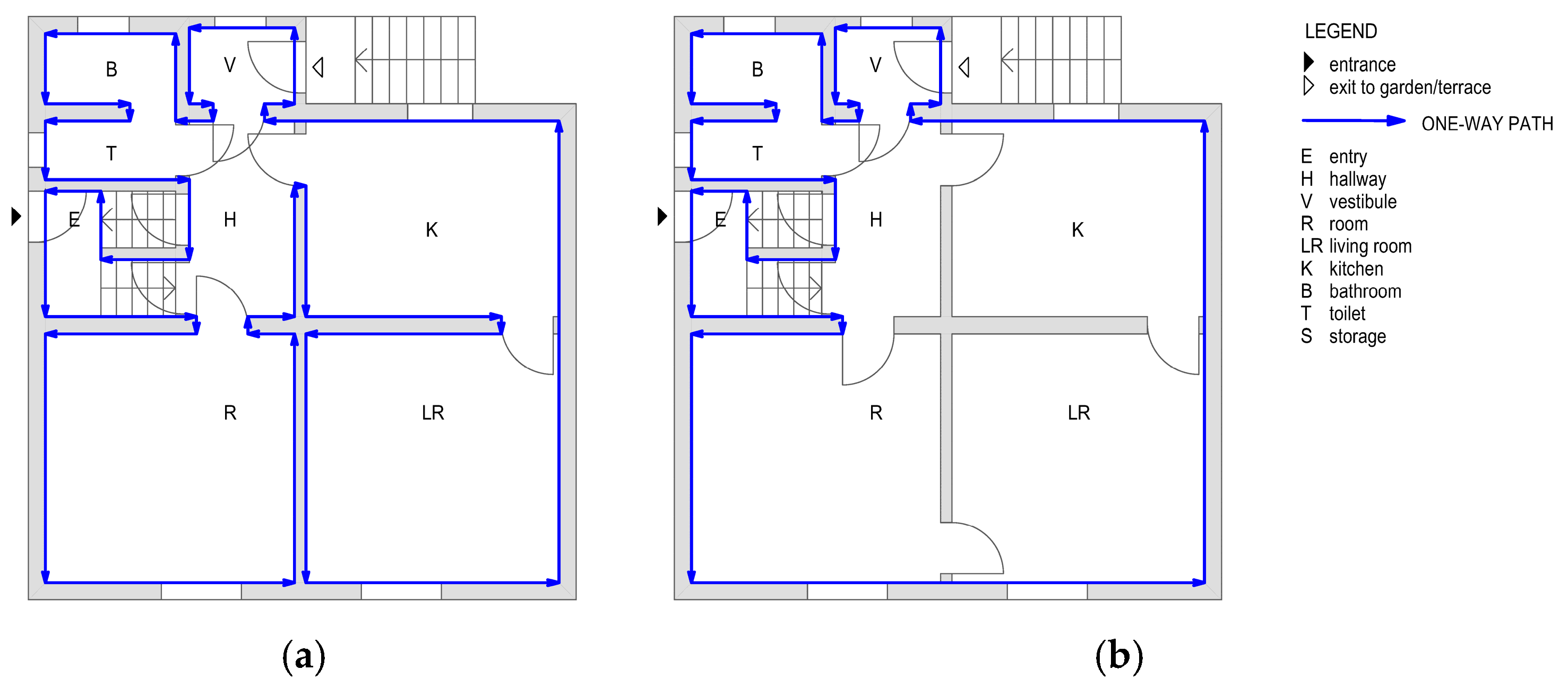
When a user/investor decides to renovate a house or apartment, they not only want to use new materials and finishes, but they also often want to renew the floor plan itself to provide better access and connections, more light, more alternative movement options, and better views. These user requirements can also be fulfilled by incorporating circular movement into the floor plan.
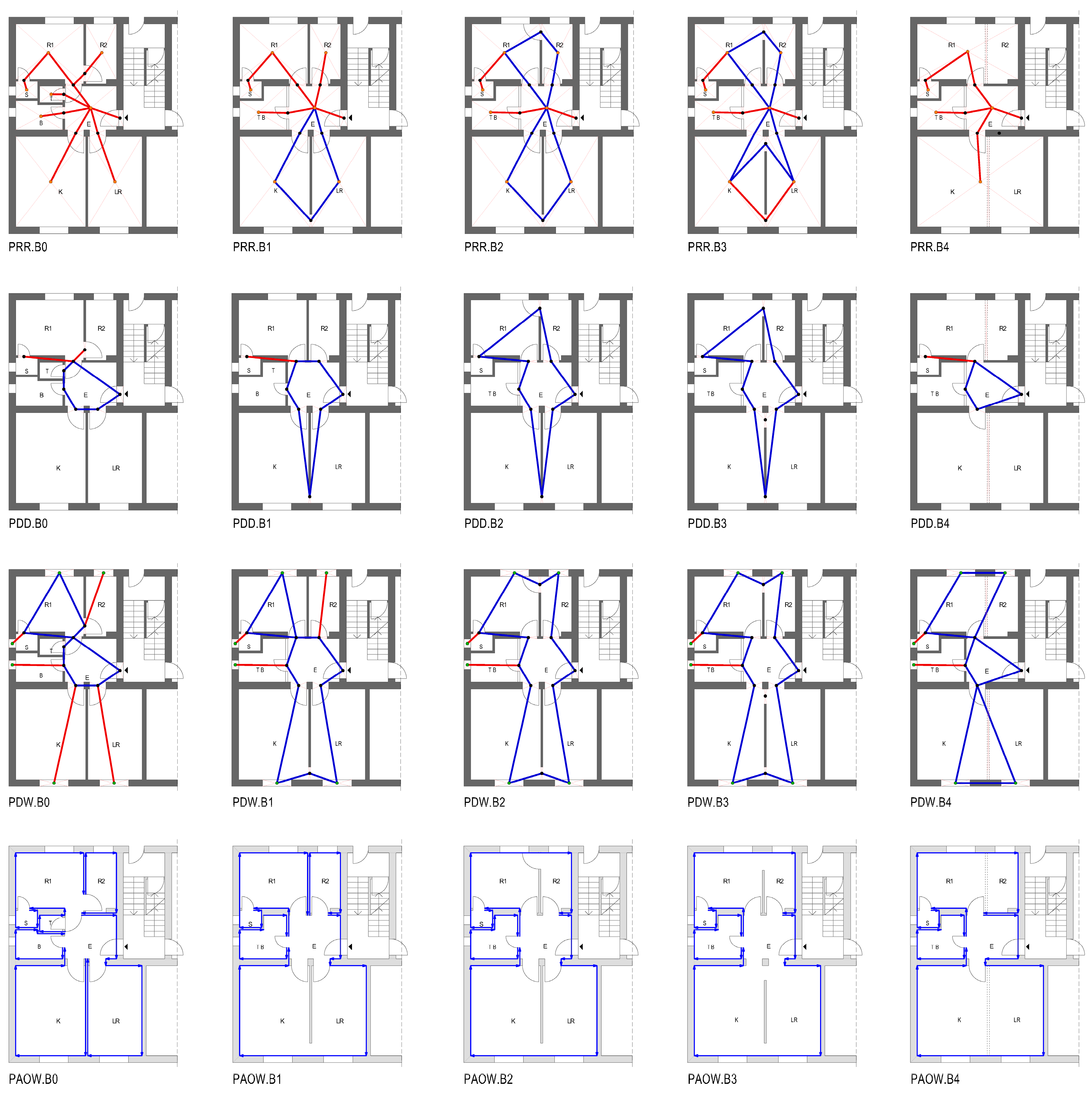
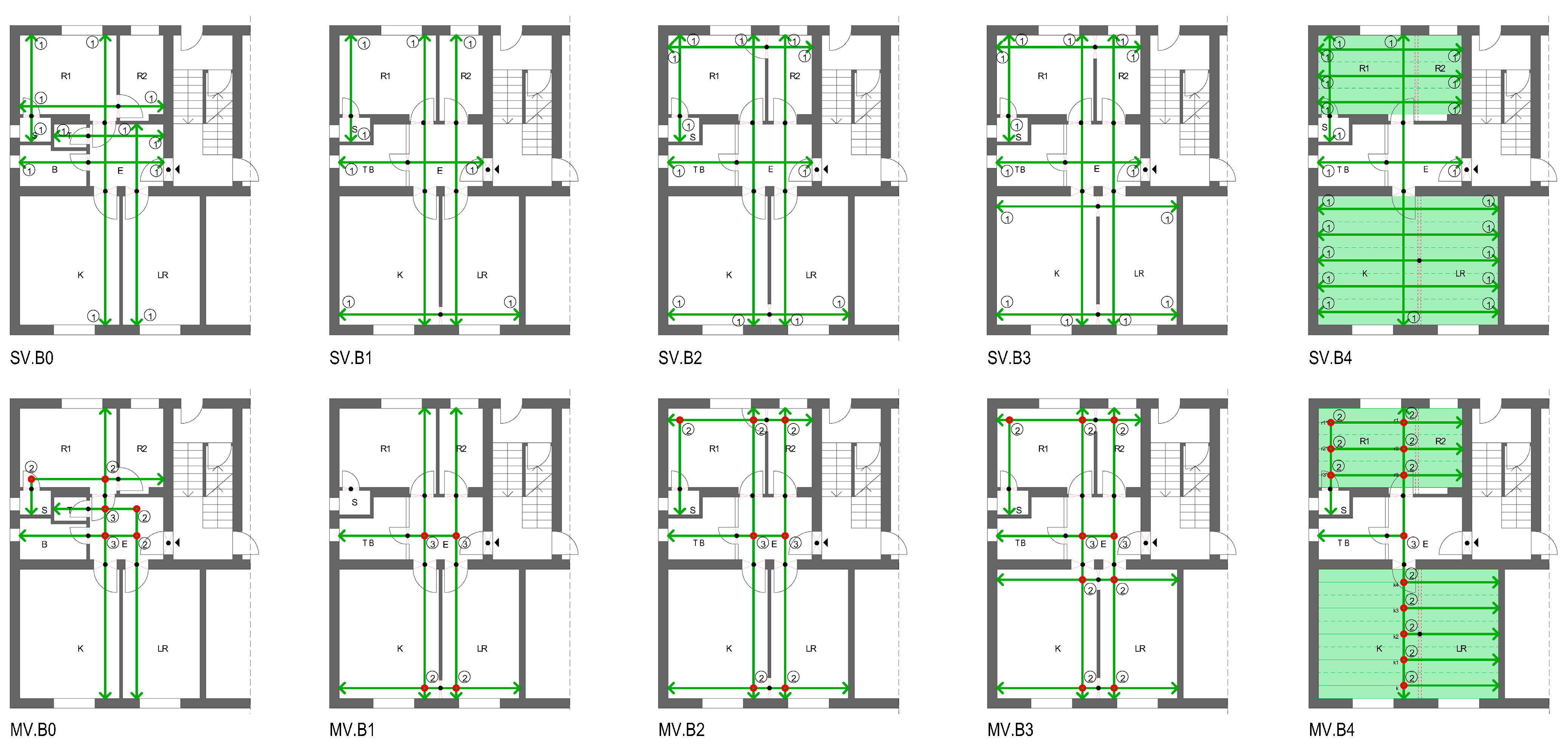
Circular movement can be established in a floor plan by inserting new doors, larger openings in the partition walls between rooms, or even knocking down a wall between two rooms. The number of newly inserted doors and their location in the floor plan of a house or apartment that we want to renovate is generally different, so it is usually always necessary to design several variants of adapted floor plans. Choosing the best variant for implementation is not always easy, especially if there are many different rooms in the floor plan. When choosing, the architect/designer is most often helped by his experience, as well as intuition.
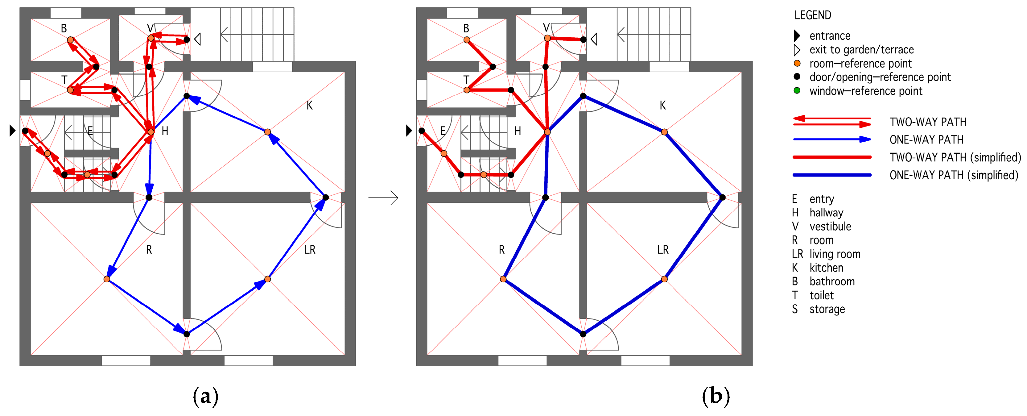
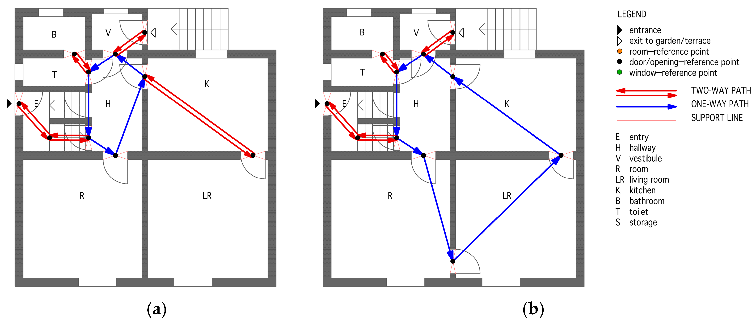
In order to select the most favorable variant design (with circular movement) in a less ‘random‘ but more systematic/rigorous way, here, it is proposed to select between variants with the help of an explicit methodological and mathematical approach. For this purpose, a new method, the so-called QLCM method (quality level of circular movement), has been developed, which allows us to calculate the quality level of the adapted floor plan variant with respect to circular movement.
The QLCM method can be used as a design tool to determine the best floor plan variant in terms of both circular movement and visibility, which offers shorter accesses, better connections between rooms, longer walking in a loop if desired, and better communications, as well as additional longer and wider views, giving the feeling of a richer and larger space, satisfaction, and generosity. In this way, the application of the proposed QLCM method leads to a better life for the occupants/users who decide/agree to implement circular movement in the floor plan during the renovation as it addresses the design gaps and possible solutions.
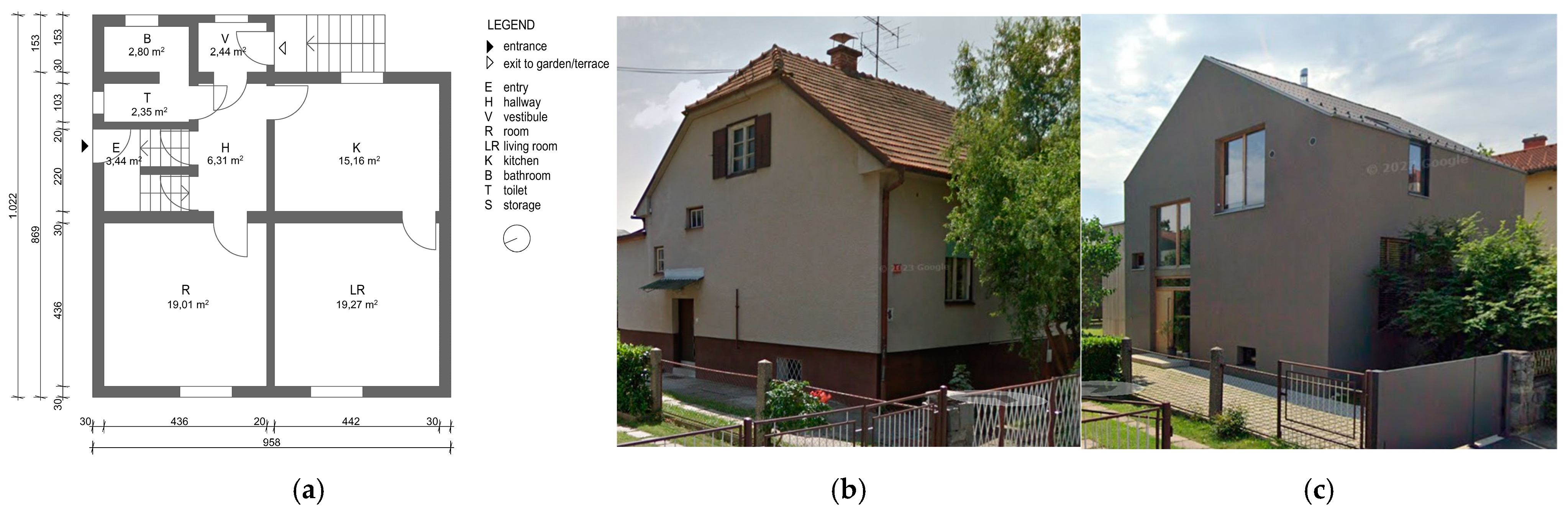
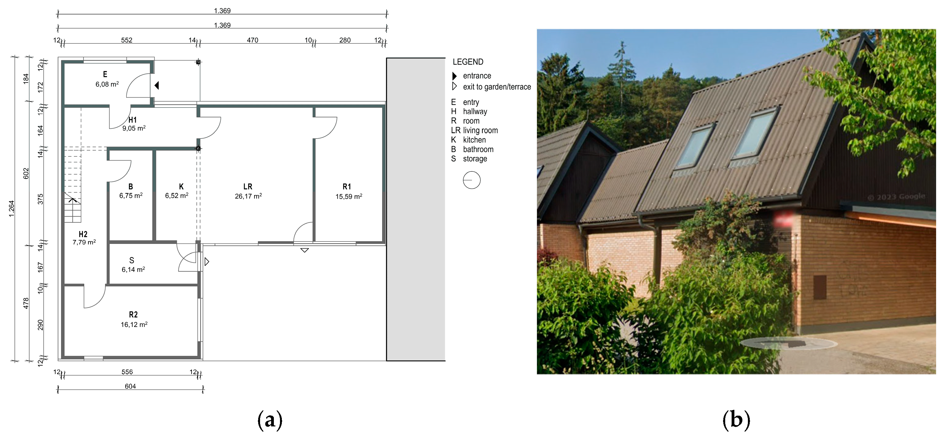
The method is tested on three case studies of the conversion of three typologically different apartments/houses from non-circular to circular layouts, which are presented at the end of this paper.

2. QLCM Method for Determining the Quality Level of Circular Movement

The new QLCM method makes it possible to easily determine the quality level of the new movement (walking) of an adapted floor plan (which includes circular movement) compared to the movement of an existing, non-adapted floor plan of a house or apartment. The method involves the analysis of aspects of the movement itself and visibility. For each aspect, a coefficient for the quality level can be calculated. For this purpose, we defined four possible characteristic paths through the adapted floor plan (with circular movement) and four different types of views across the floor. The quality level coefficient of movement consists of the sum of the partial coefficients of the quality level of movement of the four types of paths considered. The quality level coefficient of visibility is defined in such a way that it does not depend on the movement path. The total coefficient of the quality level of the new circular movement in a floor plan QLCM then represents the sum of all calculated partial coefficients.
The method presented does not involve a technologically advanced approach (e.g., ‘information modeling’) but a basic spatial analysis or ’geometric shape design’ supported by CAD (computer-aided design).

2.1. Assumptions and Limitations

The following assumptions and limitations are taken into account in this study:
  • The analysis of the circular movement of the path (calculation of the coefficients) only refers to movement/walking on one floor of the house or apartment—each floor is treated separately;
  • Spaces outside the outer walls of the house or apartment, such as balconies and terraces, are not included in the analysis;
  • The analysis of circular movement only covers the aspects of movement/walking around the home and visibility;
  • The views from the floor under consideration to the upper or lower floor(s) are not taken into account;
  • Aspects such as ventilation, lighting, static and seismic load capacity of weakened walls (due to new doors or openings), security concerns, and fire safety are not considered;
  • The influence of better lighting on the view in the rooms due to windows or new (larger) openings is not taken into account;
  • The analysis of circular movement is carried out with regard to movement/walking in empty rooms—furniture and equipment are not taken into account in the analysis;
  • The number of rooms in the adapted floor plan is still equated in the analysis with the number of rooms in the existing, non-adapted floor plan (e.g., a combined room consisting of two smaller rooms is still considered as two rooms, but with a wide opening in between);
  • Door-jambs and wall lengths of less than 30 cm are not taken into account in the analysis;
  • The viewing directions are parallel or perpendicular to each other when analyzing the visibility aspect, just like walls—views at other angles through openings are not taken into account.

2.2. Aspect of Movement on the Floor Plan

The aspect of movement/walking on the floor plan is developed by defining and comparing different possible paths on the floor plan of the house or apartment. In particular, it is important to compare the new path of the adapted house/apartment (with additional circular movement) with the path along the existing, non-adapted floor plan of the house (without a circular path, or it is significantly shorter). In this study, we defined the following four different paths through the floor plan:
  • Path from room to room (PRR);
  • Path from door to door (PDD);
  • Path from door to window (PDW);
  • Path along the outer walls (PAOW).
The path from door to door is the shortest path, and the path along the outer walls is the longest. By inserting additional doors in the walls that allow circular movement on the floor plan of the house or apartment, we increase the length of the path from door to door and shorten the path for the other three types of paths. We can start the path at any point along the path. We can move either clockwise or counterclockwise. We always return to the same starting point and always cover the same distance. The starting point of the path therefore corresponds to the end point. It is best to start the path at the entrance to the house or apartment.

2.2.1. Path from Room to Room (PRR)

With the path from room to room, we visit all the rooms on the floor plan of the house or apartment. The path from room to room is defined as moving from a certain point in the room by entering each subsequent room on the floor plan in such a way as to create the shortest possible path. The path is completed when we return to the starting point after passing through all the rooms. The purpose of this path is to walk through all the rooms on the floor plan and take a look at/inspect all the space. For this purpose, the reference points of the rooms and doors/intermediate openings to which you have to step must be determined. For the reference point of each room on the floor plan, we defined the central point of each room, and for the reference point of the door/opening, we defined the central point of the door/opening on the floor plan.
In the case of a house/apartment where circular movement on the floor plan is not possible (e.g., in the existing floor plan of a non-adapted house/apartment), a two-way path (double route) is created since when passing through all the reference center points of the rooms, one always returns to the starting point on the same path. This two-way path is executed in such a way that it is as short as possible.
Using Case A of an existing (non-adapted) house floor plan (variant PRR.A0 from the next section), shown in Figure 5a, we start with the path at the house entrance, walk along the entry and the staircase to the hallway (always through the centers), and through (the center of) the intermediate door to the room. From there, we then return through the door to the hallway, then through the door to the kitchen, and through the next door to the living room. From there, we return the same way through the living room and kitchen to the hallway. From there, we travel through the door to the vestibule and to the exit door (to the garden). From there, we return the same way to the hallway. From there, we travel further through the door to the toilet and further to the bathroom. From there, we return the same way to the hallway, and, finally, via the stairs, we return the same way back to the starting point—the house entrance. This two-way path is marked in red. In all the following drawings, the two-way paths are drawn with a single red line to facilitate drawing; see Figure 5b.
The length of the two-way path in the existing floor plan L2,e is calculated according to Equation (1), where i (i ∈ I) intermediate distances dd,i between the centers of rooms and doors are summed and multiplied by 2. Since we always return to the starting point by the same route, the length of this two-way path is normally equal to twice the sum of the distances mentioned. This is the total length of the path Ltot,e.
L2,e = Ltot,e = 2 · ⅀i dd,i
By installing additional doors/openings in the walls between different rooms, circular movement can be created in the floor plan. When such circular movement is enabled on the floor plan (in a new floor plan of an adapted house), a one-way path is created wherever circular movement takes place. With such a one-way path, it is not necessary to return along the same path, as the circular movement through the premises continues. This circular path should also be as short as possible. In most cases, it is possible to make a circular path through only a few (three) rooms or even through several rooms. Therefore, in most cases, we will not be able to include all the rooms of the home in the circular path, or this is not always practical.
Figure 6 shows an example of an adapted house (variant PRR.A1 from the next section), in which a new door is inserted in the partition between the room and the living room, allowing circular movement from the hallway through the room, living room, and kitchen back to the hallway. The path begins at the entrance of the house, see Figure 6a, goes through the entry and up the staircase (always through the reference point—the center) to the center of the hallway—this beginning of the path is the same as in the previous case of the non-adapted house. From there, we continue through the intermediate door to the room, then through the door to the living room, and then through the next intermediate door to the kitchen. From there, we continue through the door to center of the hallway. From there, we take the same path as in the existing (non-adapted) house to the vestibule, to the exit door to the garden, and then back along the same two-way path through the hallway to the toilet and bathroom, to the hallway, and through the stairs along the same path to the start of the path—to the front door. It is worth noting that the path from the hallway, through the room, living room, and kitchen back to the hallway is a one-way circular path, marked in blue, while all the remaining path is a two-way path (we return the same way), which is drawn in red in both directions. Again, the two-way paths are further drawn with a single red line; see Figure 6b.
The length of the new two-way path L2,a of the adapted floor plan is now shorter than in the previous example of the existing (non-adapted) floor plan L2,e because a new one-way path—a circular path of length L1,a—is created. The length of the total new adapted path Ltot,a, calculated as the sum of the new two-way and one-way (circular) paths of the adapted floor plan, is shorter than the total (two-way) path of the existing (non-adapted) floor plan of the house Ltot,e. The one-way circular path is marked in blue, and the two-way part of the path is marked in red. The length of the total path of the newly adapted floor plan Ltot,a is calculated with Equation (2) as the sum of the length of the two-way path L2,a and the length of the one-way circular path L1,a. In this way, the sum of j (j ∈ J) intermediate distances dd,j between the centers of rooms and doors/openings of the two-way part is multiplied by 2 and added to k (k ∈ K) distances ds,k between the reference/center points of the one-way part of the path; see Equation (3).
Ltot,a= L2,a + L1,a
Ltot,a = 2 · ⅀j dd,j + ⅀k ds,k
A very important factor when analyzing the quality of the new circular path is the proportion of the length of the one-way portion of the path compared to the total length of the path of the adapted floor plan. The higher this proportion is, the more the circular path is made in the house or apartment. This proportion is calculated with the basic coefficient K1, see Equation (4), as the ratio between the length of the one-way path L1,a and the total length of the path of the adapted floor plan Ltot,a. A higher K1 coefficient represents a higher quality of movement from the point of view of circular movement.
K1 = L1,a/Ltot,a
The total path length of the existing (non-adapted) floor plan Ltot,e is always longer than the newly adapted path with circular movement Ltot,a. The second factor in analyzing the quality of the new circular path is therefore the calculation of the basic coefficient K2, see Equation (5), which represents the ratio between the lengths Ltot,e and Ltot,a. The higher the coefficient K2 is, the better it is, because the length of the path from room to room on the floor plan has become shorter due to the introduction of circular movement, which, in turn, means a higher quality of movement.
K2 = Ltot,e/Ltot,a
The third factor in analyzing the quality of the new circular path is to calculate the proportion of the area of the rooms we pass through in a one-way circular movement compared to the total floor area of the house or apartment. The higher this proportion is, the more space is controlled by circular movement in the floor plan. It is calculated with the basic coefficient K3, see Equation (6), which is represented as the ratio between the area of the rooms Aa (through which we walk in a one-way circular movement) and the total area of the floor plan of the adapted house/apartment Atot,a. The area Aa can be easily calculated as the sum of p (pP) individual rooms Ap with a one-way circular movement; see Equation (7). A higher K3 coefficient stands for a higher quality of movement along the floor plan.
K3 = Aa/Atot,a
Aa = ⅀p Ap

2.2.2. Path from Door to Door (PDD)

The path from door to door allows us to go to/through all the doors/openings on the floor plan of the house or apartment. The path from door to door is defined in such a way that from a starting point, we walk to all subsequent doors or openings so that we cover the shortest possible distance. The path is complete when we return to the starting point after walking to/through all the doors on the floor plan. Here, too, the starting point of the path corresponds to the end point. This path is the shortest possible path to all rooms on the floor plan. The purpose of this path is a quick view into all rooms through all doors/openings, and along this path, we can also close or open all doors. For the reference points of the path to which you have to step, the centers of the doors or openings in the floor plan are defined.
The path from door to door usually contains both two-way and one-way parts of the path. We designed the path so that it is as short as possible. Using the example of an existing (non-adapted) house (variant PDD.A0 from the next section), as drawn in Figure 7a, we start the path at the entrance of the house (center of the door) and walk along the staircase. From there, we continue to the room door, continue to the kitchen door, and continue to the living room door. From there, we return to the door between the hallway and the kitchen. From there, we continue to the door to the vestibule and then to the second outer door at the outside stairs. From there, we travel back to the hallway-vestibule door. From there, we continue to the door to the toilet, then to the entrance of the bathroom, and then back to the door to the toilet. After a short walk, we travel along the hallway next to the stairs and return to the starting point of the path—the entrance of the house. Part of the path that leads back along the same path is a two-way path, which is marked in red. The remaining path is a one-way path (five sections), as shown in blue.
The total length of the path from door to door of the existing, non-adapted floor plan Ltot,e is calculated using Equations (8) and (9) with the sum of the two-way path L2,e and the one-way path L1,e.
Ltot,e = L2,e + L1,e
Ltot,e = 2 · ⅀j dd,j + ⅀k ds,k
Figure 7b shows an example of an adapted house (variant PDD.A1 from the next section), in which a new door has been inserted in the partition between the room and the living room, allowing circular movement from the hallway through the room, the living room, and the kitchen back to the hallway. The path starts at the entrance of the house, leads to the center of the beginning of the stairs, and then to the center of the end of the stairs (this part of the entire path is the same as in the non-adapted house). From there, it continues to the center of the room door, to the center of the door between the room and the living room, and then to the living room-kitchen door. From there, it continues to the hallway-kitchen door, then to the door to the vestibule, and to the exit door at the outside staircase. From there, it leads back to the hallway-vestibule door, then to the hallway-toilet door, to the entrance to the bathroom, and back to the hallway-toilet door. From there, it leads to the staircase and back to the house entrance.
The total door-to-door path length of the adapted floor plan Ltot,a is calculated according to Equations (2) and (3) from the sum of the two-way paths L2,a and the one-way paths L1,a. The analysis of the quality of the new path of the adapted floor plan is similar to the analysis of the previous case of the path from room to room. Again, an important factor is the calculation of the proportion of the length of a one-way path compared to the total length of the path of the adapted floor plan. This proportion is greater for the adapted floor plan than for the existing/non-adapted floor plan. The proportion is calculated using the basic coefficient K1; see Equation (4).
The length of the path from door to door is longer in the adapted house (due to the installation of a new door and the associated increase in the circular part of the path) compared to the length of the path of the existing, non-adapted house. The more the length of the adapted door-to-door path increases, the worse it is, as we walk longer and need more time to complete it. Conversely, the less this length increases, the better it is. This can be expressed by the basic coefficient K2, see Equation (5), which represents the ratio between the lengths Ltot,e and Ltot,a. The higher the coefficient K2 is, the better it is, because the path of the adapted floor plan increases less. This coefficient is more favorable if the new doors are located closer to each other, usually near the center of the floor plan (e.g., the hallway).
The third factor in analyzing the quality of the new circular path is the calculation of the proportion of the area of the rooms through which we pass in a one-way circular movement compared to the total area of the floor plan. This proportion is expressed by the basic coefficient K3, see Equation (6), as the ratio between the area of the spaces Aa and Atot,a.

2.2.3. Path from Door to Window (PDW)

The path from door to window allows us to go through all the doors/openings to all the windows on the floor plan of the house or apartment. The path from a door to a window is defined in such a way that from a certain starting point, we pass through all the doors/openings to all the windows on the floor plan one after the other so that we cover the shortest possible distance. Here, the term door also includes all intermediate openings between rooms. The path is complete when we return to the starting point after walking through all the doors and windows on the floor plan. The purpose of this path is to open or close all the windows (and doors) on the floor plan and at the same time take a look at the surroundings through the windows (also by checking the floor plan). The reference points of the path to which you must walk are the centers of the doors/openings and the centers of the windows.
The path from a door to a window consists of both one-way parts and two-way parts of the path (whereby we return along the same path). Using the example of the non-adapted house (variant PDW.A0 from the next section), as drawn in Figure 8a, we start with the path from the center of the entrance door, continue along the staircase, continue to the door, and continue to the room. From there, we continue to the window and back to the same door and continue to the door to the kitchen. From there, we continue to the window and then to the door to the living room, to the window, and to the living room door. From there, we go back the same way to the hallway-kitchen door. From there, we continue on to the door to the vestibule, to the two windows, and back to the vestibule-hallway door. Then, we continue to the hallway-toilet door, to the opening to the bathroom, to the window, and back to the opening. From there, we continue to the window of the toilet and back to the hallway-toilet door. From there, we continue to the stairs down to (the center of) the entrance door—the starting point.
The total length of the path from door to window of the existing, non-adapted floor plan Ltot,e is calculated using Equations (8) and (9) with the sum of the path in two directions L2,e and the path in one direction L1,e.
Figure 8b shows an example of an adapted house (variant PDW.A1 from the next section) in which a new door has been inserted in the partition between the room and the living room, allowing circular movement. The beginning and end parts of the path of the adapted floor plan are the same as that of the non-adapted floor plan. The difference is in enabling circular movement, where one goes from the hallway-room door to the room window, from there to the room-living room door, to the living room window, then to the living room-kitchen door, then to the kitchen window, and to the hallway-kitchen door. The total required path from the doors to the windows of the adapted floor plan Ltot,a is calculated using Equations (2) and (3). Since circular movement is added to the path, the length of the path of the adapted floor plan is shorter than the path of the non-adapted floor plan. The two-way path is drawn in red; the one-way path is shown in blue.
When analyzing the quality of a new adapted floor plan, it is necessary to calculate the ratio between the length of the one-way path and the total length of the path (both of the adapted floor plan), the ratio between the total lengths of non-adapted and adapted floor plans, and the proportion of the area of rooms with circular movement compared to the total floor area of a house or apartment. For this purpose, Equations (4)–(6) are used to determine the basic coefficients K1, K2, and K3.

2.2.4. Path Along the Outer Walls (PAOW)

The path along the perimeter of the outer walls makes it possible to walk along all the outer walls on the floor plan of the house or apartment. The path is defined as the shortest possible path. Since the entire path runs in a continuous line, it also includes paths along/around some interior walls. This path is the longest possible path in one direction (one-way path) on the floor plan. Again, the start point of the path corresponds to the end point. The purpose of this path is to obtain a complete overview of the house/apartment as a whole and the inspection of the exterior walls/windows.
The path along the outer walls is a one-way path (contains no two-way path sections). Using the example of a non-adapted house (variant PAOW.A0 from the next section), as shown in Figure 9a, we start with the path at the house entrance (in the center of the front door), turn right and walk along the wall of the staircase, and turn right through the hallway-room door into the room. Then, we walk around the room along all four walls back to the door, where we turn right again and walk along the wall of the hallway to the hallway-kitchen door. From there, we go into the kitchen and along two walls to the kitchen-living room door. There, we turn right and walk along all four walls back to the kitchen-living room door. In the kitchen, we walk along two walls to the hallway-kitchen door, and so on along the walls of all the other rooms until we return to the starting point—the house entrance.
The total length of the path along the perimeter of the outer walls of the existing, non-adapted floor plan Ltot,e is calculated using Equation (10), where k (kK) individual distances ds,k (from corner to corner of the walls) are added to form a one-way path L1,e.
Ltot,e = L1,e = ⅀k ds,k
Figure 9b shows an example of an adapted house (variant PAOW.A1 from the next section), in which a new door is inserted in the partition between the room and the living room, allowing a shorter circular movement through the room, living room, and kitchen. This path is basically very similar to the path of the non-adapted floor plan, with the difference that we do not take the circumferential path around the interior walls between the room, hallway, kitchen, and living room. Instead, this path leads from the room along the outer walls through the new (room-living room) door directly into the living room and then along the same path to the house entrance, as in the existing floor plan. The total length of the path along the perimeter of the outer walls of the adapted floor plan Ltot,a corresponds to the length of the adapted one-way path L1,a, which is calculated in analogy to the above case; see Equation (10).
The length of the path along the perimeter of the outer walls of the adapted floor plan Ltot,a is shorter than the length along the outer walls of the non-adapted floor plan Ltot,e. Since most or all of the paths along the perimeter of the outer walls can be considered as circular paths, the basic coefficient K2 is decisive for analyzing this path; see Equation (5). It represents the ratio between the lengths Ltot,e and Ltot,a. The higher the coefficient K2 is, the better it is, because the new path is shortened. For this path, the basic coefficient K2 is more favorable/higher if the new doors are located closer to the outer walls, that is, away from the center of the floor plan (the opposite case than the path from door to door). The basic coefficients K1 and K3 should also be calculated. Usually, their values are equal or almost equal to 1.

2.3. Aspect of Visibility over the Floor Plan

The aspect of visibility across the floor plan of a house or apartment comprises the analysis of the various views in the rooms of the floor. Only views from one room into another room (or several rooms) through open doors or other openings in the floor plan are analyzed here. The more such views there are and the longer they are, the more space in the house or apartment we control with our eyes. We get the feeling of a larger space. Visibility around the house through the windows is not analyzed/considered. In this study, the visibility analysis includes several different types of views:
  • One-directional (single) view;
  • Two-directional view;
  • Multi-directional (multiple) view;
  • Wide view.
The one-directional (single) view is a simple view from one room to another room on the floor plan. It is a view in one direction only. If you can see into two or more neighboring rooms from one point, it is called a two-directional view or a multi-directional view. The wide view is a view with a significantly wider field of vision. Wide two- and multi-directional views provide better visibility than a one-directional view. Note that when looking from one room to another, it is assumed that the line of sight passes through the center (reference point) of the connecting door or opening.

2.3.1. One-Directional View

The length of the view through the door from one room to another is defined as the length from the beginning (end wall) of the first room to the end (end wall) of the second room. At the same time, this is the longest possible view through the intermediate door into both observed rooms. This view is referred to as a one-directional view; see Figure 10a (variant SV.A0 from the next section). The more such views there are in the floor plan, the better it is. Figure 10a shows a view in one direction from the living room to the kitchen. Since the view in one direction from the kitchen can be seen through the same door and the same line of sight back into the living room, the lines of sight of this and the other one-directional views in Figure 10b are marked with arrows on both sides.

2.3.2. Two-Directional View

The visibility from one room to other neighboring rooms is better the more different viewing directions are possible from the room. This depends on the number of open doors in the room from which we are looking. As the walls on the floor plan are usually at right angles to each other, the viewing directions from the room into the neighboring rooms are also at right angles to each other. If we install a door in each of two mutually perpendicular boundary walls of a room, then we enable two mutually perpendicular views from this room into two different neighboring rooms. When we step onto the intersection of the directions of the two views, we see both neighboring rooms simultaneously (through the open doors). Such a view from one point is called a two-directional view; see Figure 11 (variant MV.A0 from the next section). As the installation of new doors in walls creates additional, mainly two-directional views, the two-directional views are treated separately here and not as multi-directional views.
A two-directional view is longer, and therefore better, the longer the two individual views are seen from the point of intersection. This is particularly the case if the intersection of the viewing directions and the two doors are not in the middle of the floor plan but closer to the outer walls of the floor plan. From the point of view of visibility, a two-directional view is of better quality than a one-directional view because we can see two neighboring rooms instead of one, that is, a larger part of the floor of the house or apartment. The more two-directional views are enabled on the floor plan, the better it is.

2.3.3. Multi-Directional View

When we see three or four different neighboring rooms from the intersection of the normally mutually perpendicular lines of sight (viewing directions), such a view is called a multi-directional view or multiple view; see Figure 12 (variant MV.A0 from the next section). This view is created by turning around the intersection point and making a (full) circle. From the point of view of visibility, the multi-directional view is better than the two-directional view or the one-directional view. With a multi-directional view, we can control several rooms from one point at the same time; at the same time, we have the feeling that the common space in the house/apartment is larger. The more multi-directional views we have on the floor plan and the longer they are, the better it is—the better the visibility.

2.3.4. Wide View

When we look through a wide door or other wide opening from one room to another neighboring room, we can say that we have a wide view since the field of vision of such a view is relatively wide. A wide view from one room into another is normally obtained when the partition wall or its larger part is removed. The quality of the view is then higher than with the previously mentioned (narrow) single view.
The wide view can be established as a one-directional wide view in one direction, as a two-directional wide view in one or both directions, and as a multi-directional wide view in different directions. The more wide views that are activated on the floor plan and the longer these views are, the better it is—the better the visibility. Note that a wide view does not give the point intersection with other views, but it gives a line intersection with another single view or an area intersection as the intersection of two or more wide views. We simplified this by dividing the wide view into several individual line views. The number of line views that make up a wide view is simply determined as a whole number resulting from the ratio between the width of the wide opening and the width of the average door; see Figure 13 (variant W.A4 from the next section). The minimal width of the wide view is suggested as two average door widths (from 1.60 to 2.0 m). The maximal width is not fixed; it usually depends on the width of the wide opening.

2.3.5. The Analysis of Views

The aspect of visibility includes the analysis of all views from all rooms of the floor plan. By installing new doors in the partition walls of the existing (non-adapted) floor plan, which allowed circular movement, we obtained new views, especially new two-directional views. The number of views in the adapted floor plan has therefore increased. The more new doors are installed and the more circular movements are possible, the more new views we obtain. The first factor of the visibility aspect is therefore the calculation of the ratio between the number of all views of the adapted floor plan NVtot,a and the number of all views of the non-adapted floor plan NVtot,e. This ratio is expressed by the basic coefficient K4; see Equation (11). NVtot,a is obtained from the sum of all views NVa,s from all s (sS) individual rooms of the adapted floor plan. NVtot,e is calculated analogously by the sum of all views NVe,s from all s (sS) individual rooms of the existing, non-adapted floor plan. The higher the K4 coefficient is, the better it is because the number of mainly two-directional views has increased due to the insertion of new doors for circular movement.
K4 = NVtot,a/NVtot,e = (⅀s NVa,s)/(⅀s NVe,s)
In view totals, a single view counts as one view, a two-directional view as two views, a three-directional view as three views, and a four-directional view as four views. The wide view is evaluated in terms of the width of the opening, that is, with a (rounded-up) whole number resulting from the ratio between the width of the wide opening and the width of the average story door (usually two to five views). In this way, each direction of the wide view is evaluated separately, regardless of whether it occurs as a one-, two-, or multi-directional view.
Note that the number of views for each room is counted twice, separately for normal one-directional line views and separately for two- and multi-directional views from the intersection points. The number of one-directional views and the number of two- and multi-directional views are added to the total number of all views (NVtot,a, NVtot,e). The same applies to the lengths of the views. For example, Figure 14 shows the following: (a) the one-directional views across the floor plan (variant SV.A0 from the next section) and (b) the two- and multi-directional views (variant MV.A0 from the next section). E.g., the room and living room each comprise only one one-directional view, the kitchen comprises two one-directional views plus one two-directional view, and the hallway comprises three one-directional views plus one three-directional view and one four-directional view. In this way, the room has one view, the living room has one view, the kitchen has 1 + 1 + 2 = 4 views, and the hallway has 1 + 1 + 1 + 3 + 4 = 10 views.
A very important factor when considering visibility is the number of neighboring rooms that can be seen from each room on the floor plan. From a room, we can see one, two, or more neighboring rooms on the floor plan. The more adjacent rooms we can see, the better it is because these views allow us to control more of the space of the house or apartment. By installing new doors for circular movement in the partitions of the existing (non-adapted) floor plan, we also obtained new, mainly two-directional views. This increased the number of adjacent rooms that we can see. This increase is expressed by the basic coefficient K5, see Equation (12), which is the ratio between the number of the visible adjacent rooms of the adapted floor plan NRtot,a and the number of the visible adjacent rooms of the existing floor plan NRtot,e. NRtot,a is obtained from the sum of all visible adjacent rooms NRa,s from all s (sS) individual rooms of the adapted floor plan. NRtot,e is calculated analogously from the sum of all visible adjacent rooms NRe,s from all s (sS) individual rooms of the existing, non-adapted floor plan. The higher the coefficient K5 is, the better it is, because by inserting new doors for circular movement, you can see into more side rooms.
K5 = NRtot,a/NRtot,e = (⅀s NRa,s)/(⅀s NRe,s)
Adding up the number of rooms is very simple. For example, if we look at Figure 14a, we can see that from the room, we can see into two other rooms (hallway and vestibule), from the living room, we can see into only one other room (kitchen), and from the hallway, we can see into five other rooms (room, entry, toilet, vestibule, and kitchen). In this way, we add up the number of other rooms that we can see from all the rooms on the floor plan.
Another important factor for visibility is the length of the views from individual rooms on the floor plan. The longer this length is, the better it is because, with views, we control more of the floor plan area. If new doors for circular movement are installed in the partition walls of the existing (non-adapted) floor, we obtain new views and thus a greater length of views. This increase is expressed by the basic coefficient K6, see Equation (13), which is the ratio between the sum of the lengths of all views of the adapted floor plan LVtot,a and the sum of the lengths of all views of the existing floor plan LVtot,e. LVtot,a is obtained from the sum of all lengths of the views LVa,s from all s (sS) individual rooms of the adapted floor plan. LVtot,e is calculated analogously from the sum of all lengths of the views LVe,s from all s (sS) individual rooms of the existing, non-adapted floor plan. The higher the coefficient K6 is, the better it is because we obtain a higher sum of view lengths by inserting new doors for circular movement.
K6 = LVtot,a/LVtot,e = (⅀s LVa,s)/(⅀s LVe,s)
These lengths are measured in each room of the floor plan of the house or apartment. Note that the lengths of views are measured twice. First, all one-directional view lengths from all rooms are summed, and second, all two- and multi-directional view lengths from each intersection point (of the view lines) are also summed (by analogy of counting the number of views).
We already mentioned that with the installation of new doors for circular movement, we obtain additional, mainly two-directional views. A two-directional view is longer, and therefore better, the longer the two individual views are, viewed from the intersection to the end of the adjacent rooms. This is particularly the case if the intersection of the viewing directions and the two doors are located closer to the outer walls. Conversely, the lengths of the two views are shorter if the intersection point and the doors are located closer to the center of the floor plan (hallway). The length of the two-directional view from the intersection point is calculated as the sum of the two distances of the two views from the point of intersection to the end of the two adjacent rooms into which the views extend (sometimes through several adjacent rooms).
In a wide view, we also measure the view lengths for each line of sight separately in one direction and separately for two and more directions from intersection points (there are as many lines as the average door fits into the opening). However, this measurement can also be simplified: we multiply the average length of a line by the number of lines in the wide view.

2.4. Coefficient of the Quality Level of Circular Movement, QLCM

With the developed method, we can calculate the coefficient of the quality level of the new circular movement (walking) QLCM of the adapted floor plan. It is calculated based on a comparison of the new path (with circular movement) of the adapted floor plan and the old path of the existing, non-adapted floor plan of the house or apartment.
The analysis of the quality level of circular movement includes the aspects of movement and visibility across the floors. We calculate a specific coefficient for each aspect. New doors can be inserted into the existing floor plan of a house or apartment at different locations, and the number of doors inserted can also be different. Different topologies with different positions and numbers of inserted doors (with circular movement) result in m (mM) different variants of adapted floor plans.
Furthermore, we consider g (g ∈ 4)—four different characteristic paths for the aspect of movement: the path from room to room (PRR), the path from door to door (PDD), the path from door to window (PDW), and the path along the outer walls (PAOW).
For the four path types, basic coefficients K1g,m, K2g,m, and K3g,m are calculated. To ensure that none of the basic coefficients K1g,m, K2g,m, and K3g,m is preferred, it is necessary to normalize all these coefficients. These coefficients are normalized separately. For example, after checking all coefficients K1g,m (in all path types and variants), the coefficient with the highest value K1max and the coefficient with the smallest value K1min can be found. The normalized coefficient K1Ng,m is then determined by min–max normalization according to Equation (14). The other two basic coefficients K2g,m and K3g,m are also calculated in this way. Min–max normalization, also called min–max scaling, is a calculation process of converting the given data (K1g,m to K3g,m) into its corresponding values (KNg,m) in a fixed boundary, here [0, 1]. The highest value of the normalized coefficient is thus equal to 1, the smallest is 0, and all (other) coefficients have values between 0 and 1.
K1Ng,m = (K1g,mK1min)/(K1maxK1min)
For each of the mentioned g path types (g ∈ 4) and each of the m (mM) adapted floor plan variants, the path coefficients KCMg,m are proposed to be calculated separately. The path coefficients KCMg,m are calculated by adding the corresponding normalized basic coefficients K1Ng,m, K2Ng,m, and K3Ng,m; see Equation (15).
KCMg,m = K1Ng,m + K2Ng,m + K3Ng,m    g = 1, 2, 3, 4
The movement coefficient KCMSm for each of the m-th adapted variants of the floor plan, which represents the calculated quality level of the circular path from the point of view of the movement itself, is equal to the sum of the path coefficients of the four defined different paths KCMg,m (g = 1, 2, 3, 4); see Equation (16).
KCMSm = ⅀g KCMg,m
Again, in order to sum up the influence of both aspects, i.e., mobility and visibility, equally, the movement coefficients KCMSm of all m variants must be normalized. The normalized movement coefficients KCMSNOR,m are calculated with min–max normalization using Equation (17), where KCMSmax and KCMSmin represent the highest and lowest values between all values of the coefficients KCMSm of the adapted variants.
KCMSNOR,m = (KCMSmKCMSmin)/(KCMSmaxKCMSmin)
The aspect of visibility includes the analysis of all views from all rooms through the doors or other floor openings. This aspect is designed to be independent of the aforementioned path types. Here, it is necessary to calculate the visibility coefficients KCMVm for each of the m-th adapted floor plan variants, which represents the calculated quality level of circular movement from the visibility point of view.
In order to determine the coefficients KCMVm, the basic coefficients K4m, K5m, and K6m must be calculated. These basic coefficients are normalized so that none is dominant. They are normalized separately within m (mM) different variants. Min–max normalization is applied. For example, the basic coefficient K4m is normalized using Equation (18). The other two coefficients are normalized in the same way. All coefficients take values between 1 and 0.
K4Nm = (K4mK4min)/(K4maxK4min)
The visibility coefficients KCMVm are simply equal to the sum of the corresponding normalized basic coefficients K4Nm, K5Nm, and K6Mm; see Equation (19). The visibility coefficients KCMVm are then normalized. The normalized visibility coefficients KCMVNOR,m are calculated by min–max normalization according to Equation (20), where KCMVmax and KCMVmin represent the highest and lowest values between all values of the coefficients KCMVm of the adapted variants.
KCMVm = K4Nm + K5Nm + K6Nm
KCMVNOR,m = (KCMVmKCMVmin)/(KCMVmaxKCMVmin)
The quality level coefficient of the circular movement over the m-th (mM) floor plan variant of the house or apartment QLCMm is finally calculated as the sum of the normalized coefficients of the movement aspect KCMSNOR,m and the visibility aspect KCMVNOR,m; see Equation (21). The higher the coefficient QLCMm is, the higher is the quality level of the new path due to the additional circular movement in the adapted floor plan.
QLCMm = KCMSNOR,m + KCMVNOR,m
After checking the coefficients QLCMm of all m variants, we can determine the highest calculated coefficient QLCMmax (its highest possible value is 2). According to the proposed method, the variant of the adapted floor plan that has the highest coefficient—QLCMmax—has the highest quality in terms of movement and visibility and is therefore selected for realization.
The QLCM method requires a total of sixteen steps from the determination of the adapted floor plan variants with circular movement to the calculation of the maximal quality level coefficient of circular movement QLCMmax; see Table 1.

3. Case Studies

For research purposes, three existing floor plans, cases A, B, and C, were used as the basis for the creation of variants that allowed the circulation paths and the length and number of views to be measured. Different housing typologies (single-family house, multi-family house, and atrium house) and different floor plan typologies were used to demonstrate the application of the method. The selected floor plan sizes range from approx. 50 to 100 m2, which corresponds to average-sized residential units in Europe [42].

3.1. Data (Samples)

3.1.1. Case A

Case A is a medium-sized detached house in a suburb, which was built in 1939 and renovated in 2017. The house has a basement, a mezzanine floor, and an attic, where the mezzanine of approx. 71 m2 was used for the analysis. In its original state (Figure 15), floor plan A0 consists of the entrance to the house, a hallway, a separate toilet and an adjoining bathroom, a kitchen, a living room, and an additional bedroom, as well as an exit to the garden via a vestibule. The floor plan is characterized by a series of individual rooms that are traditionally separated in their basic functions. The house originally had rather small windows with windowsills. The renovation of the house (floor plan A4) aimed to improve the spatial connections between the rooms (e.g., kitchen and living room), ensure better circulation between the rooms, and increase the feeling of spaciousness and visibility. Some walls were demolished, the window openings were enlarged (as French doors), and a terrace was added. The house was originally built of brick, and the ceilings were made of wood.

3.1.2. Case B

Case B is a two-story residential building with four identical apartments, located near the city center and built in 1935. The apartment used for the purpose of this study is located on the mezzanine floor and covers approx. 65 m2 (Figure 16). The original apartment floor plan B0 consists of the entrance area, which is a main connection and leads to a separate toilet and bathroom, a separate kitchen and a separate living room, and two interconnected rooms with a storage room. The apartment was thoroughly renovated in 2003, with several improvements made to allow better circulation between the rooms and to bring natural light into the entrance area by installing a translucent glass wall (floor plan B2). The appearance of the façade of the house did not change. The load-bearing walls are made of brick, and the ceiling is made of wood.

3.1.3. Case C

Case C is a row house with an inner atrium made of prefabricated timber construction (Figure 17), which was built in the 1980s and functionally adapted twice since 2010 (for two families with different needs). The L-shaped floor plan is based on the principle of zoning (living and sleeping areas). In its original state, the ground floor of approx. 100 m2 consists of an entrance area leading into two corridors, adjoined on one side by a bathroom and a bedroom (from which a staircase also leads to the attic); on the other side are the living room, the adjoining kitchen, and a storage room, as well as an additional room for various purposes. All living spaces face the inner courtyard, which serves as an outdoor terrace. The renovation included some minor changes to improve the connections within the house.

3.2. Paths and Views

The existing (non-adapted) floor plan and four different variants of the adapted floor plans were examined for all three case studies under consideration. For this purpose, paths and views were drawn in all the floor plans mentioned. Paths from room to room (PRR), from door to door (PDD), from door to window (PDW), and along the outer walls (PAOW) were drawn for each variant. The same applies to the one-directional views (single views—SVs) and the multi-directional views (multiple views—MVs). These drawn paths and views were used to measure/determine the basic coefficients from k1 to k6 (see the following section).
It should also be mentioned that the interventions in the existing (non-adapted) floor plan were context-related and aimed at finding new sensible floor plan solutions. At the same time, the basic principles of the interventions were established, namely, the addition of doors/passages in selected places to test the new possibilities of circulation paths, as well as the removal of parts or entire non-load-bearing walls.

3.2.1. Case A

The floor plan variants for case A are shown in Figure 18 and Figure 19. The non-adapted floor plan is marked as A0. In this variant, the hallway (H) next to the entry (E) functions as the central communication point of the house, leading to all adjacent rooms such as the room (R), the kitchen (K), the vestibule (V), and the toilet (T), from which other rooms can be reached, such as the bathroom (B) from the toilet (T) and the living room (LR) from the kitchen (K). The A0 floor plan was transformed during the process into the A1 floor plan, in which an additional door was inserted in the wall between the room (R) and the living room (LR), whose position is towards the outer walls, which enables a new communication path. In adapted floor plan A2, three of the doors (H-K, K-LR, R-LR) were moved to the center of the house to test what happens when the openings between the rooms are relatively close to each other. In variant A3, an additional passageway was inserted between the hallway (H) and the kitchen (K), and a door between the room (R) and the living room (LR) was eliminated. Finally, in variant A4, the most rigorous interventions were made, such as the demolition of the entire non-load-bearing wall between the kitchen (K) and the hallway (H), which thoroughly redesigned the function of the hallway as the original communication space, and the enlargement between the kitchen (K) and the living room (LR) to the width of four doors. Furthermore, as in variant A1, an additional door was inserted in the wall between the room (R) and the living room (LR), and the opening between the toilet (T) and the bathroom (B) was enlarged to the width of two doors—thus merging both rooms into one functional unit. A raised terrace was added to the outside of the house.

3.2.2. Case B

The floor plan variants for case B are shown in Figure 20 and Figure 21. The non-adapted floor plan is labeled B0. In this variant, the entry (E) functions as the central communication point of the apartment, leading to all adjoining rooms such as the room (R1), kitchen (K), living room (LR), bathroom (B), and toilet (T). In addition, two further rooms are accessible from room 1 (R1), namely, room 2 (R2) and the mini-storage room (S). Floor plan B0 was converted into floor plan B1, in which an additional door was inserted in the wall between the kitchen (K) and the living room (LR), which faces the outside walls and thus enables a new communication path. In addition, the bathroom (B) and the toilet (T) were merged into one space (TB). In adapted floor plan B2, an additional door was inserted between the two rooms (R1 and R2), which was positioned towards the outer walls. In variant B3, an additional passageway was inserted between the kitchen (K) and the living room (LR). Finally, in variant B4, the most rigorous interventions were made, such as the demolition of the entire non-load-bearing wall between the kitchen (K) and the living room (LR) and the demolition of the entire non-load-bearing wall between the two rooms (R1 and R2).

3.2.3. Case C

The floor plan variants for case C are shown in Figure 22 and Figure 23. A non-adapted floor plan is marked as C0. In this variant, the floor plan does not have a single central communication space, but it is L-shaped and extends with two corridors in two directions of the atrium house. Hallway 1 (H1) leads to the living room (LR), which in turn leads to the kitchen (K) with an adjoining storage room (S) on one side and to the room (R1) on the other. Hallway 2 (H2) is a connection to the bathroom and another room (R2). Floor plan C0 was converted to floor plan C1 during the process, with an additional door inserted in the wall between hallway 1 (H1) and the kitchen (K). In adapted floor plan C2, a passageway was created from the kitchen (K) directly to room 2 (R2) via the storage room (S), which was divided into two parts. In variant C3, an additional door was inserted between the living room (LR) and room 1 (R1). Finally, in variant A4, the most rigorous intervention was carried out, namely, the demolition of the entire non-load-bearing wall between the living room (LR) and room 1 (R1).

3.3. Results

The calculations of all necessary coefficients are shown here for all three cases considered, in particular, the coefficients of the quality level of circular movement QLCM. For each case, the calculation of the selection of the most suitable variant of the adapted floor plan is shown. Note that the basic coefficients from k1 to k6 are calculated based on the measurements of paths and views from the previous section. While the lengths of the paths and views are given in meters (m), the areas of the rooms are given in square meters (m2).

3.3.1. Case A

The input data and the calculated coefficients for Case A are shown in Table 2, Table 3 and Table 4. While Table 2 shows the input data and the calculated basic coefficients K1, K2, and K3 for the aspect of movement, Table 3 shows the input data and the basic coefficients K4, K5, and K6 for the aspect of visibility. Table 4 shows the calculated normalized basic coefficients, the path coefficients, the two normalized aspect coefficients, and, finally, the quality level coefficients of circular movement QLCM of four floor plan variants of Case A.
Adapted variant A4 has the highest QLMC coefficient (1.55) and is therefore the best variant in terms of the quality level of circular movement. This variant is the third best variant in the sequence (the penultimate variant) in terms of the aspect of movement (KCMSNOR = 0.55), but it is the first in terms of the aspect of visibility (KCMVNOR = 1.00). The visibility aspect is highest in variant A4 due to the wide views.
Note that adapted floor plan variants A2 and A1 are the best variants in terms of the path from room to room (PRR), variants A3 and A2 are the best in terms of the path from door to door (PDD), variants A4 and A1 are the best in terms of the path from door to window (PDW), and variant A2 is the best in terms of the path along the outer walls (PAOW).
The results of case study A show that the insertion of additional doors or openings in the walls between the individual spaces of the housing unit influences the length of the circulation path, whereby the length also depends on their position—the further apart they are, the longer they are, as the highest result of variant PRR.A1 also shows. The insertion of additional doors also allows for longer views, especially if the doors are positioned so that they are aligned with each other (as in the case of the additional opening between the kitchen (K), the hallway (H), and facing the entry (E) in variants A2, A3, and A4) or if they allow for multiple views. Variant A4 has improved the visual dimension the most compared to the non-adapted and the other adapted variants, as the rather rigorous intervention has created wide views that have transformed the originally rather conservative floor plan into a more contemporary, open, connected, and spacious living space.

3.3.2. Case B

The input data and the calculated coefficients for Case B are shown in Table 5, Table 6 and Table 7. Table 5 shows the input data and the calculated basic coefficients for the aspect of movement, while Table 6 shows the basic coefficients for the aspect of visibility. Table 7 shows the calculated normalized basic coefficients, the path coefficients, the two normalized aspect coefficients, and the quality level coefficients of circular movement QLCM of four floor plan variants for Case B.
Adapted floor plan variant B3 exhibits the highest QLMC coefficient (1.72). It is therefore the best variant in terms of the quality level of circular movement among all variants. This variant is the best variant in terms of the aspect of movement (KCMSNOR = 1.00), but it is the second best in terms of the aspect of visibility (KCMVNOR = 0.72).
Adapted floor plan variant B1 is the best variant in terms of the path from room to room (PRR), variant B2 is the best in terms of the path from door to door (PDD), and variant B3 is the best in terms of the path from door to window (PDW) and the path along the outer walls (PAOW).
Although in Case B, the floor plan was different from Case A, the study shows some similar results, namely, that additional doors between spaces increased the length of the one-way circular path compared to the two-way path, as well as the length and number of views (with each additional door, the results improved—from B1 to B2 to B3). However, the case with the most rigorous interventions (B4) was not the best in terms of overall results, as the demolition of the non-load-bearing walls between the two rooms (R1 and R2) and between the kitchen (K) and the living room (LR) significantly reduced the possibility of circulation between the spaces (as they became a single space), although they were improved in terms of a visual dimension.

3.3.3. Case C

The input data and the calculated coefficients for Case C are listed in Table 8, Table 9 and Table 10. The basic coefficients are shown in Table 8 for the aspect of movement and in Table 9 for the aspect of visibility. Table 10 shows the calculated normalized basic coefficients, the path coefficients, the two normalized aspect coefficients, and the quality level coefficients of circular movement QLCM of four floor plan variants for Case C.
Since adapted floor plan variant C4 has the highest QLMC coefficient (2.00), it is the best variant in terms of the quality level of circular movement. This variant is the best variant in terms of the aspect of movement (KCMSNOR = 1.00) and in terms of the aspect of visibility (KCMVNOR = 1.00).
Adapted floor plan variant C4 is the best variant in terms of the path from room to room (PRR) and the path from door to door (PDD), variant C3 is the best in terms of the path from door to window (PDW), and variant C2 is the best in terms of the path along the outer walls (PAOW).
The floor plan of Case C showed a different composition of spaces compared to Cases A and B, although we obtained similar results. The addition of an extra door to the selected spaces, such as the kitchen (K), room 1 (R1), room 2 (R2), and the storage room (S), extended the length of the circular one-way path. Furthermore, the strategic positioning of the doors and openings aligned with each other (the H1-K-S1-R2 visual axis) allowed for longer and multiple views in addition to a longer one-way circular path. As in Case A, the most efficient variant in terms of movement and visibility was the one with the most rigorous transformation (C4).

4. Discussion and Conclusions

Planning the floor plans of houses and apartments is a complex task in which various factors and criteria must be weighed in order to meet functional needs, cultural norms, and overarching guidelines. Depending on individual needs and wishes, however, it is difficult to find the perfect solution. Nevertheless, there are measurable aspects that can influence the quality level of residential units. In this study, a specific segment of the floor plans is discussed, namely, the benefit of circular movement in combination with the aspect of visibility. Both aspects, i.e., circular movement and visibility, are not only important because they enable the daily use and experience of the living space, but they also have many other implications that have not been addressed in this article—such as the impact on ventilation, the flexibility to reconfigure the floor plans over time, or even the social dimension.
This article presents a new method, the so-called QLCM method, with which it is possible to determine the quality level of the circular movement of floor plans of houses or apartments. When adapting a floor plan, to which we want to add a new circular movement, several variants are usually possible. A different number of new doors or openings and their different arrangements can result in a relatively high number of variants of different floor plans. Determining the most favorable variant is not a simple process. The presented QLCM method makes this selection possible in a systematic mathematical way by calculating a special QLCM coefficient for each variant.
The calculation of the QLCM coefficient of the quality level of circular movement comprises two aspects: the movement aspect and the visibility aspect. To calculate the movement aspect, four different characteristic paths were defined/planned across the floor plan of a house or apartment: path from room to room, path from door to door, path from door to window, and path along the outer walls. To calculate the visibility aspect, four different types of views were analyzed: the one-directional view, the two-directional view, the multi-directional view, and the wide view. Based on the measured/calculated lengths of the different paths and the number and lengths of the different sight lines, each alternative floor plan variant (with circular movement) was compared with the existing (non-adapted) floor plan in order to calculate the basic coefficients, the path coefficients, and the aspect coefficients. To ensure that some of the basic coefficients did not predominate and that the movement and visibility aspects were treated equally, the basic coefficients and aspect coefficients were normalized using min–max normalization. The normalized aspect coefficients were summed together to form the QLCM coefficient for each variant. The variant with the highest QLCM coefficient was the most favorable from the point of view of the quality of circular movement and was therefore selected for implementation.
In the presented study, we analyzed circular movement from only two aspects: the movement aspect and the visibility aspect. Both aspects are, in most cases, sufficient for an effective analysis of circular movement, but under certain conditions, other aspects can also be decisive. As the method will continue to develop, it will be useful to add the following aspects to the method in the future:
  • The aspect of enlarging the floor plan by adding a new room (extension), a terrace, a shed roof, a carport, or a garden room;
  • The aspect of the view from an oblique angle, also from the floor under consideration to the upper or lower floor(s);
  • The aspect of lighting the house or apartment through windows/openings;
  • The aspect of the static and seismic load-bearing capacity of walls weakened by new doors or openings;
  • The aspect of the placement of furniture and appliances in the rooms, which could significantly alter the paths and views;
  • Last but not least, the aspect of use by people with disabilities.
The principle of the circular path could also be applied in research or used in planning practice for other building typologies, such as primary and secondary schools or college buildings, kindergartens, large shopping centers, healthcare buildings (where possible), retirement homes, and offices—in short, anywhere where greater social interaction between users or user groups is beneficial. Exploring the flexibility and adaptability of circular layouts would also be interesting in the context of special situations (such as the COVID-19 pandemic), where many people were forced to stay indoors and had to compensate for their psychological and physical need to move.
It would also be useful to automate the method, whereby the acquisition of data from CAD and the calculation of coefficients would be carried out automatically. Parametric modeling could help to provide more detailed parameters and create more variants and solutions that meet users’ needs. In addition, the integration of digital interfaces with augmented reality could allow stakeholders to experience and evaluate floor plan variants in immersive environments, leading to better-informed design decisions. We anticipate that in the future, technologies will enable the help of intelligent assistants in the design of floor plans of houses and apartments. Tools such as generative design algorithms could autonomously explore floor plan variants. In addition, the combination of digital tools with artificial intelligence could enable predictive analytics to provide insights into users’ needs and lifestyles, which could improve the design and quality of homes.
To summarize, the QLCM method was tested on three different case studies: a medium-sized detached house, a two-story apartment building, and a prefabricated atrium house. In each case, four different refurbishment variants were considered, incorporating circular movement. The QLCM coefficients were calculated for all cases and variants using the QLCM method. After checking the obtained values, the highest QLCM coefficient was determined for each case, based on which, the most favorable variant of the case was selected for implementation.
When analyzing circular movement in the three case studies, the following main findings were identified:
  • The renovation of the floor plan of a house or apartment according to the principles of circular movement can only be carried out at the request or with the consent of the users;
  • Users must specify which areas or specific rooms should be included in the circular movement and whether they want less movement with shorter accesses (a shorter circular loop) or more movement (a longer circular loop);
  • By appropriately inserting new doors or openings in the partition walls, we can always create circular movement in the floor plan of the house/apartment;
  • A different number and position of the newly inserted doors can be inserted into the renovated floor plan, creating a variety of different variants;
  • With the proposed QLCM method, it is always possible to calculate the most suitable variant in terms of circular movement and visibility;
  • The most suitable variant that is calculated usually meets the expectations of the architect and the user;
  • By inserting doors/openings closer to the center of the floor plan, we usually shorten the accessibility to rooms with a shorter circular movement loop;
  • If we insert doors/openings closer to the outer walls of the floor plan, we allow more movement/walking in the floor plan with a longer loop of circular movement;
  • If we insert the new doors so that they are aligned on a straight axis, we obtain a long and rich view;
  • If we establish circular movement in the floor plan, we always obtain new, especially two-directional, views through newly inserted doors/openings that increase visibility;
  • If we create circular movement through newly inserted wide openings, we always obtain new wide views that significantly increase visibility;
  • Circular movement enables faster access, better connection of spaces, and more movement/walking (if we want it) and gives the user a feeling of greater satisfaction and generosity as well as the feeling of a larger and richer space;
  • By introducing circular movement, we obtain a less rigid and friendlier floor plan of the house/apartment, which leads to a better life for the user.
In this way, this study makes a valuable contribution to both academic research and practical applications in architectural design as it focuses on improving the quality of residential floor plans by introducing the QLCM method, which quantitatively evaluates the aspects of circular movement and visibility. The main strengths of the method are as follows:
  • Improving the user experience: Circular movement provides better connectivity between spaces, shortens walking distances, and improves spatial perception, which has a direct impact on residents’ quality of life.
  • Addressing design gaps: There is a lack of systematic tools for architects to evaluate and compare floor plan designs, especially with a focus on movement and visibility; this method fills this gap by providing measurable criteria.
  • Relevance for renovation projects: Renovating existing buildings to improve spatial efficiency is becoming increasingly important in urban areas where optimizing space is critical.
  • Basis for technological integration: This study provides a basis for integrating advanced technologies such as BIM, AI, and automation into the evaluation and design of floor plans, responding to the digital transformation in architecture.
The proposed QLCM method was found to be very useful in determining the most suitable alternative variant with circular movement when renovating floor plans of houses and apartments. The method also provides a deeper insight into the quality of the design of the variants and how they compare with each other. It answers the questions of which aspect is most important, which paths are most suitable, and which views are the richest. The QLCM method proved to be effective and easy to apply not only in research but also in daily design practice.

Author Contributions

Conceptualization, K.P. and S.K.; methodology, S.K.; validation, K.P. and S.K.; formal analysis, K.P. and S.K.; investigation, K.P. and S.K.; resources, K.P. and S.K.; data curation, K.P. and S.K.; writing—original draft preparation, K.P. and S.K.; writing—review and editing, K.P. and S.K.; visualization, K.P. and S.K.; supervision, K.P. and S.K.; funding acquisition, S.K. All authors have read and agreed to the published version of the manuscript.

Funding

This research received no external funding.

Data Availability Statement

All relevant data are included in the paper.

Acknowledgments

The authors would like to acknowledge the Slovenian Research and Innovation Agency (ARIS) for partly financing this research within the frame of program P2-0129.

Conflicts of Interest

The authors declare no conflicts of interest.

References

  1. Ching, F.D.K. Architecture-Form, Space, & Order, 5th ed.; John Wiley & Sons, Inc.: Hoboken, NJ, USA, 2023; ISBN 978-1119853374. [Google Scholar]
  2. Alexander, C.; Ishikawa, S.; Murray, S. A Pattern Language: Towns, Buildings, Constructions; Oxford University Press: New York, NY, USA, 1977. [Google Scholar]
  3. Tawil, N.; Sztuka, I.M.; Pohlmann, K.; Sudimac, S.; Kühn, S. The living space: Psychological well-being and mental health in response to interiors presented in virtual reality. Int. J. Environ. Res. Public Health 2021, 18, 12510. [Google Scholar] [CrossRef]
  4. Fu, M.; Liu, R.; Hon, C.K.H. Walkability evaluation of building circulation based on user preference. Eng. Constr. Archit. Manag. 2021, 28, 2904–2924. [Google Scholar] [CrossRef]
  5. Lederer, A. Circulation areas—Places for interaction or an El Dorado for building regulations? In Designing Circulation Areas; Schittich, C., Ed.; DETAIL: Munich, Germany, 2013; pp. 14–21. ISBN 978-3-95553-140-9. [Google Scholar] [CrossRef]
  6. Shin, J.; Lee, J.K. Indoor Walkability Index: BIM-enabled approach to Quantifying building circulation. Autom. Constr. 2019, 106, 102845. [Google Scholar] [CrossRef]
  7. Natapov, A.; Kuliga, S.; Dalton, R.C.; Hölscher, C. Linking building-circulation typology and wayfinding: Design, spatial analysis, and anticipated wayfinding difficulty of circulation types. Archit. Sci. Rev. 2020, 63, 34–46. [Google Scholar] [CrossRef]
  8. Paulus, C. Understanding Achitectural Circulation Diagrams: A Guide. Available online: https://illustrarch.com/articles/architectural-diagrams/27045-what-is-architectural-circulation-diagram.html (accessed on 15 October 2024).
  9. Bielefeld, B. Spaces in Architecture: Areas, Distances, Dimensions; Birkhäuser: Basel, Switzerland, 2018; ISBN 9783035617238. [Google Scholar]
  10. Mark, K. Space Planning Basics, 3rd ed.; John Wiley & Sons, Inc.: Hoboken, NJ, USA, 2009; ISBN 978-0-470-23178-4. [Google Scholar]
  11. Schittich, C. (Ed.) Designing Circulation Areas: Staged Paths and Innovative Floorplan Concepts, 1st ed.; DETAIL: Munich, Germany, 2013; ISBN 978-3-95553-140-9. [Google Scholar]
  12. Hanson, J. Decoding Homes and Houses; Cambridge University Press: Cambridge, UK, 2003; ISBN 0521543517. [Google Scholar] [CrossRef]
  13. Heckmann, O.; Schneider, F. Floor Plan Manual Housing, 4th ed.; Müller, A., Ed.; Birkhäuser: Basel, Switzerland, 2018; ISBN 978-3-0356-1149-6. [Google Scholar]
  14. Hillier, B.; Hanson, J. The Social Logic of Space; Cambridge University Press: Cambridge, UK, 2009; ISBN 9780511597237. [Google Scholar] [CrossRef]
  15. Stickells, L. Conceiving an architecture of movement. Archit. Res. Q. 2010, 14, 41–51. [Google Scholar] [CrossRef]
  16. Gehl, J.; Svarre, B. How to Study Public Life; Island Press-Center for Resource Economics: Washington, DC, USA, 2013; ISBN 9781610915250. [Google Scholar] [CrossRef]
  17. Leupen, B.; Mooij, H. Housing Design: A Manual; NAi010 Publishers: Rotterdam, The Netherlands, 2022; ISBN 978-90-5662-826-0. [Google Scholar]
  18. Bračič, A.; Keršič, A.; Zupančič, B.; Kosec, M. Iščem Stanovanje: 100 let Organizirane Stanovanjske Gradnje; Muzej za Arhitekturo in Oblikovanje (MAO): Ljubljana, Slovenia, 2022; ISBN 9789616669825. [Google Scholar]
  19. Dawes, M.J.; Ostwald, M.J.; Lee, J.H. Examining control, centrality and flexibility in Palladio’s villa plans using space syntax measurements. Front. Archit. Res. 2021, 10, 467–482. [Google Scholar] [CrossRef]
  20. Emmons, P. Intimate Circulations: Representing Flow in House and City. AA Files J. Archit. Assoc. Sch. Archit. 2005, 51, 48–57. [Google Scholar]
  21. Manuel, G. Housing: New Alternatives—New Systems; Actar Publishers: Barcelona, Spain, 1998; ISBN 3-7643-58870-X. [Google Scholar]
  22. Dosen, A.S.; Ostwald, M.J. Prospect and refuge theory: Constructing a critical definition for architecture and design. Int. J. Des. Soc. 2013, 6, 9–23. [Google Scholar] [CrossRef]
  23. Ostwald, M.J.; Dawes, M.J. The Spatio-Visual Geometry of the Hollyhock House: A Mathematical Analysis of the ‘Wright Space’ using Isovist Fields. Nexus Netw. J. 2020, 22, 211–228. [Google Scholar] [CrossRef]
  24. Koch, W. Baustilkunde, Band 2; Bertelsmann Lexikon Verlag: Munich, Germany, 1993; ISBN 9783570105252. [Google Scholar]
  25. Smith, E.A.T. Case Study Houses: The Complete CSH Program 1945-1966; Gossel, P., Shulman, J., Eds.; Taschen America: Los Angeles, CA, USA, 2021; ISBN 978-3836587877. [Google Scholar]
  26. Kim, S.S.; Yang, I.H.; Yeo, M.S.; Kim, K.W. Development of a housing performance evaluation model for multi-family residential buildings in Korea. Build. Environ. 2005, 40, 1103–1116. [Google Scholar] [CrossRef]
  27. Yoon, C.; Kim, M.; Park, J.; Lee, J. A case study on a flexible floor plan design for South Korean apartments using two types of margins. Open House Int. 2022, 47, 207–217. [Google Scholar] [CrossRef]
  28. Sitar, M.; Šprah, N. Use value assessment for raising the quality of housing. AR Archit. Res. 2016, 1, 6–25. [Google Scholar]
  29. Macarthur, J.; Moulis, A. Movement and figurality: The circulation diagram and the history of the architectural plan. In Celebration, Proceedings of the 22nd Annual Conference of the Society of Architectural Historians, Australia and New Zealand; The University of Queensland: St Lucia, Australia, 2005; pp. 231–236. [Google Scholar]
  30. Bafna, S. Space Syntax: A Brief Introduction to its Logic and Analytical Techniques. Environ. Behav. 2003, 35, 17–29. [Google Scholar] [CrossRef]
  31. Dursun, P. Space Syntax in Architectural Design. J. Chem. Phys. 1978, 69, 1207–1212. [Google Scholar]
  32. Frederick, C. The New Housekeeping. Efficiency Studies in Home Management; Garden City: New York, NY, USA, 1913. [Google Scholar]
  33. Mura, C.; Pajarola, R.; Schindler, K.; Mitra, N. Walk2Map: Extracting Floor Plans from Indoor Walk Trajectories. Comput. Graph. Forum 2021, 40, 375–388. [Google Scholar] [CrossRef]
  34. Victorio, E.R.; Kowaltowski, D.C.C.K. Circulation as a Concept Graphically Represented in a Game-Like Manner to Support the Design Process in Architecture. In International Conference on Science and Technology Education; da Silva, L.F.M., Ferreira, A.J.M., Eds.; Springer: Cham, Switzerland, 2023; pp. 39–54. [Google Scholar] [CrossRef]
  35. Lee, J.K.; Kim, M.J. BIM-enabled conceptual modelling and representation of building circulation. Int. J. Adv. Robot. Syst. 2014, 11, 1–8. [Google Scholar] [CrossRef]
  36. Jeong, W.S.; Kong, B.C.; Yum, S.G. Developing a Framework for Data-Driven Generation of Building Information Modeling from Sketches: Enhancing Efficiency in Space Configuration and Building Performance Analysis. Appl. Sci. 2024, 14, 3013. [Google Scholar] [CrossRef]
  37. Palacín, J.; Rubies, E.; Bitriá, R.; Clotet, E. Path Planning of a Mobile Delivery Robot Operating in a Multi-Story Building Based on a Predefined Navigation Tree. Sensors 2023, 23, 8795. [Google Scholar] [CrossRef] [PubMed]
  38. Rodrigues, E.; Sousa-Rodrigues, D.; Teixeira de Sampayo, M.; Gaspar, A.R.; Gomes, Á.; Henggeler Antunes, C. Clustering of architectural floor plans: A comparison of shape representations. Autom. Constr. 2017, 80, 48–65. [Google Scholar] [CrossRef]
  39. Hua, H.; Hovestadt, L.; Wang, Q. Flexible high-rise apartments with sparse wall-frame structure: A data-driven computational approach. Front. Archit. Res. 2024, 13, 639–649. [Google Scholar] [CrossRef]
  40. Ko, J.; Ennemoser, B.; Yoo, W.; Yan, W.; Clayton, M.J. Architectural spatial layout planning using artificial intelligence. Autom. Constr. 2023, 154, 105019. [Google Scholar] [CrossRef]
  41. Carta, S. Self-Organizing Floor Plans. Harvard Data Sci. Rev. 2021, 1–35. [Google Scholar] [CrossRef]
  42. Khajehzadeh, I.; Vale, B. How house size impacts type, combination and size of rooms: A floor plan study of New Zealand houses. Archit. Eng. Des. Manag. 2017, 13, 291–307. [Google Scholar] [CrossRef]
Figure 1. Examples of different floor plan typologies with regard to movement paths: (a) corridor/hall floor plan, (b) floor plan with the circular path, and (c) continuous floor plan.
Buildings 15 00444 g001
Figure 2. Characteristic organization of floor plans with a circular layout: (a) residential unit with a central core; (b) residential unit with interconnected rooms.
Buildings 15 00444 g002
Figure 3. Accesses to rooms: (a) closed cell; (b) open cell.
Buildings 15 00444 g003
Figure 4. Examples of floor plans with a circular path: (a) Neolithic dwelling with a fireplace in the center, (b) Mongolian yurt with a heart in the center, (c) schematic representation of a Roman atrium house, (d) schematic representation of a floor plan with an enfilade.
Buildings 15 00444 g004
Figure 5. The path from room to room. The two-way path: (a) double red line, (b) a single red line.
Buildings 15 00444 g005
Figure 6. The path from room to room: (a) the one-way path is marked with a single blue line and the two-way path with double red lines; (b) single blue and red lines.
Buildings 15 00444 g006
Figure 7. The path from door to door: (a) existing floor plan, (b) adapted floor plan.
Buildings 15 00444 g007
Figure 8. The path from door to window: (a) existing floor plan, (b) adapted floor plan.
Buildings 15 00444 g008
Figure 9. The path along the outer walls: (a) existing floor plan, (b) adapted floor plan.
Buildings 15 00444 g009
Figure 10. The one-directional view: (a) from one room to another, (b) in both directions.
Buildings 15 00444 g010
Figure 11. The two-directional view.
Buildings 15 00444 g011
Figure 12. The multi-directional views: (a) the three-directional view, (b) the four-directional view.
Buildings 15 00444 g012
Figure 13. The wide views: (a) the one-directional wide view, (b) the two-directional wide view in one direction, (c) the two-directional wide view in two directions; red dots are intersection points.
Buildings 15 00444 g013
Figure 14. Number of views: (a) the one-directional views, (b) the two- and multi-directional views; red dots are intersection points.
Buildings 15 00444 g014
Figure 15. Case A: (a) the original floor plan of the mezzanine level; (b) the house in its original state; (c) the house after the renovation.
Buildings 15 00444 g015
Figure 16. Case B: (a) the original floor plan of the mezzanine level of one apartment; (b) photo of the house with 4 apartments.
Buildings 15 00444 g016
Figure 17. Case C: (a) the original floor plan of the ground level; (b) photo of the atrium house.
Buildings 15 00444 g017
Figure 18. Floor plan variations for case A (0—existing, 1 to 4—adapted) and representation of different aspects of movement: PRR—path from room to room, PDD—path from door to door, PDW—path from door to window, PAOW—path along outer walls.
Buildings 15 00444 g018
Figure 19. Floor plan variations for case A (0—existing, 1 to 4—adapted) and representation of different aspects of visibility (SV—singular view, MVs—multiple views).
Buildings 15 00444 g019
Figure 20. Floor plan variants for case B (0—existing, 1 to 4—adapted) and representation of different aspects of movement: PRR—path from room to room, PDD—path from door to door, PDW—path from door to window, PAOW—path along outer walls.
Buildings 15 00444 g020
Figure 21. Floor plan variations for Case B (0—existing, 1 to 4—adapted) and representation of different aspects of visibility (SV—singular view, MVs—multiple views).
Buildings 15 00444 g021
Figure 22. Floor plan variations for case C (0—existing, 1 to 4—adapted) and representation of different aspects of movement: PRR—path from room to room, PDD—path from door to door, PDW—path from door to window, PAOW—path along outer walls.
Buildings 15 00444 g022
Figure 23. Floor plan variations for case C (0—existing, 1 to 4—adapted) and representation of different aspects of visibility (SV—singular view, MVs—multiple views).
Buildings 15 00444 g023
Table 1. Summary of the QLCM method.
StepAction of the QLCM Method
1.Determination of m (mM) adapted floor plan variants.
ASPECT OF MOVEMENT
2.Drawing of the four paths: PRR (g = 1), PDD (g = 2), PDW (g = 3), and PAOW (g = 4) into the floor plans.
3.Determination of the path lengths (Lg,m) and the areas of the rooms (Ag,m).
4.Calculation of the basic coefficients K1g,m, K2g,m, and K3g,m.
5.Normalization of the basic coefficients K1Ng,m, K2Ng,m, and K3Ng,m.
6.Calculation of the path coefficients KCMg,m.
7.Calculation of the movement coefficients KCMSm.
8.Normalization of the movement coefficients KCMSNOR,m.
ASPECT OF VISIBILITY
9.Drawing of the one-, two-, and multi-directional views and wide views into the floor plans.
10.Determination of the number of views (NVm) and rooms (NRm), as well as the lengths of the views (LVm).
11.Calculation of the basic coefficients K4m, K5m, and K6m.
12.Normalization of the basic coefficients K4Nm, K5Nm, and K6Nm.
13.Calculation of the visibility coefficients KCMVm.
14.Normalization of the visibility coefficients KCMVNOR,m.
ASPECTS OF MOVEMENT AND VISIBILITY
15.Calculation of the quality level coefficients of circular movement QLCMm.
16.Selection of the maximal coefficient QLCMmax—the best floor plan variant.
Table 2. Case A, the basic coefficients for the aspect of movement.
Basic Coefficients K1g,m, K2g,m, K3g,mExisting Floor A0Adapted Variant A1 m = 1Adapted Variant A2 m = 2Adapted Variant A3 m = 3Adapted Variant A4 m = 4
PRR * g = 1L1,a L1,e0.0019.3018.468.4215.78
L2,a L2,e56.2626.7026.7044.7839.48
Ltot,e56.26
Ltot,a 46.0045.1653.2055.26
Aa 59.7559.7521.4759.75
Atot,a70.7770.7770.7770.7770.77
K1g,m 0.420.410.160.29
K2g,m 1.221.251.061.02
K3g,m 0.840.840.300.84
PDD g = 2L1,a L1,e9.1220.5312.2712.1320.02
L2,a L2,e21.9410.5610.5610.5611.14
Ltot,e31.06
Ltot,a 31.0922.8322.6931.16
Aa 59.7559.7559.7559.75
Atot,a70.7770.7770,7770.7770.77
K1g,m 0.660.540.530.64
K2g,m 1.001.361.371.00
K3g,m 0.840.840.840.84
PDW g = 3L1,a L1,e18.8735.9442.9122.3531.21
L2,a L2,e42.649.749.7428.4410.52
Ltot,e61.51
Ltot,a 45.6852.6550.7941.73
Aa 64.5464.5464.5464.54
Atot,a70.7770.7770.7770.7770.77
K1g,m 0.790.820.440.75
K2g,m 1.351.171.211.47
K3g,m 0.910.910.910.91
PAOW g = 4L1,a L1,e53.8551.6744.7848.5548.20
L2,a L2,e-----
Ltot,e53.85
Ltot,a 51.6744.7848.5548.20
Aa70.7770.7770.7770.7770.77
Atot,a70.7770.7770.7770.7770.77
K1g,m 1.001.001.001.00
K2g,m 1.041.201.111.12
K3g,m 1.001.001.001.00
* PRR—path from room to room, PDD—path from door to door, PDW—path from door to window, PAOW—path along outer walls, L1,a: length of the one-way path, L2,a L2,e: lengths of the two-way paths (a—adapted, e—existing floor plan), Ltot,e: total length of the existing path, Ltot,a = L1,a + L2,a: total length of the adapted path, Aa: area of rooms with a circular path, Atot,a: total area of the floor plan, K1g,m = L1,a/Ltot,a, K2g,m = Ltot,e/Ltot,a, K3g,m = Aa/Atot,a.
Table 3. Case A, the basic coefficients for the aspect of visibility.
Basic Coefficients K4m, K5m, K6mExisting Floor A0Adapted Variant A1 m = 1Adapted Variant A2 m = 2Adapted Variant A3 m = 3Adapted Variant A4 m = 4
NV1e, NV1a *1214141327
NVMe, NVMa1115151460
NVtot,e23
NVtot,a 29292787
NRtot,e18
NRtot,a 20202222
LV1e, LV1a86.12104.08104.08101.94201.82
LVMe, LVMa56.6387.4869.1472.65341.73
LVtot,e142.75
LVtot,a 191.56173.22174.59543.55
K4m 1.261.261.173.78
K5m 1.111.111.221.22
K6m 1.341.211.223.81
* NV1e, NV1a: sum of all one-directional views (e—existing, a—adapted floor plan), NVMe, NVMa: sum of all multi-directional views, NVtot,e, NVtot,a: sum of all views (e—existing, a—adapted floor plan), NRtot,e, NRtot,a: sum of the visible adjacent rooms, LV1e, LV1a: sum of the lengths of all one-directional views, LVMe, LVMa: sum of the lengths of all multi-directional views, LVtot,e, LVtot,a: sum of the lengths of all views (e—existing, a—adapted floor plan), K4m = NVtot,a/NVtot,e, K5m = NRtot,a/NRtot,e, K6m = LVtot,a/LVtot,e.
Table 4. Case A, the quality level coefficient of circular movement QLCM.
Calculated CoefficientsExisting Floor A0Adapted Variant A1 m = 1Adapted Variant A2 m = 2Adapted Variant A3 m = 3Adapted Variant A4 m = 4
Aspect of Movement
PRR * g =1K1Ng,m 0.310.300.000.15
K2Ng,m 0.470.530.130.04
K3Ng,m 0.770.770.000.77
KCMg,m = K1Ng,m + K2Ng,m + K3Ng,m 1.551.600.130.96
PDD g =2K1Ng,m 0.600.450.440.57
K2Ng,m 0.000.770.790.00
K3Ng,m 0.770.770.770.77
KCMg,m = K1Ng,m + K2Ng,m + K3Ng,m 1.371.992.001.34
PDW g =3K1Ng,m 0.750.790.330.70
K2Ng,m 0.740.360.451.00
K3Ng,m 0.870.870.870.87
KCMg,m = K1Ng,m + K2Ng,m + K3Ng,m 2.362.021.652.57
PAOW g =4K1Ng,m 1.001.001.001.00
K2Ng,m 0.090.430.230.26
K3Ng,m 1.001.001.001.00
KCMg,m = K1Ng,m + K2Ng,m + K3Ng,m 2.092.432.232.26
KCMSNOR,mKCMSm = ⅀g KCMg,m 7.378.046.017.13
= (KCMSmKCMSmin)/(KCMSmaxKCMSmin)0.671.000.000.55
Aspect of visibility
K4N 0.030.030.001.00
K5N 0.000.001.001.00
K6N 0.050.000.001.00
KCMVNOR,mKCMVm = K4Nm + K5Nm + K6Nm 0.080.031.003.00
= (KCMVmKCMVmin)/(KCMVmaxKCMVmin)0.020.000.331.00
Aspects of movement and visibility
QLCMmQLCMm = KCMSNOR,m + KCMVNOR,m 0.691.000.331.55
QLCMmaxQLCMmax between all QLCMmQLCMmax = 1.55 (variant A4)
* PRR—path from room to room, PDD—path from door to door, PDW—path from door to window, PAOW—path along outer walls, normalized basic coefficients: KN,m = (KmKmin)/(KmaxKmin) for all K1, K2,…K6.
Table 5. Case B, the basic coefficients for the aspect of movement.
Basic Coefficients K1g,m, K2g,m, K3g,mExisting Floor B0Adapted Variant B1 m = 1Adapted Variant B2 m = 2Adapted Variant B3 m = 3Adapted Variant B4 m = 4
PRR * g = 1L1,a L1,e0.0025.3214.5425.230.00
L2,a L2,e49.3414.9028.8426.0828.86
Ltot,e49.34
Ltot,a 40.2243.3851.3128.86
Aa 41.2858.6158.610.00
Atot,a64.7764.7764.7764.7764.77
K1g,m 0.630.340.490.00
K2g,m 1.231.140.961.71
K3g,m 0.640.900.900.00
PDD g = 2L1,a L1,e8.9521.6312.8221.638.69
L2,a L2,e7.300.005.503.445.50
Ltot,e16.25
Ltot,a 21.6318.3225.0714.19
Aa6.941.2858.6158.616.90
Atot,a64.7764.7764.7764.7764.77
K1g,m 1.000.700.860.61
K2g,m 0.750.890.651.15
K3g,m 0.640.900.900.11
PDW g = 3L1,a L1,e19.7234.1232.6834.1236.32
L2,a L2,e35.287.2614.647.267.26
Ltot,e55.00
Ltot,a 41.3847.3241.3843.58
Aa18.7253.1058.6158.6158.61
Atot,a64.7764.7764.7764.7764.77
K1g,m 0.820.690.820.83
K2g,m 1.331.161.331.26
K3g,m 0.820.900.900.90
PAOW g = 4L1,a L1,e58.2855.8853.3452.5456.23
L2,a L2,e-----
Ltot,e58.28
Ltot,a 55.8853.3452.5456.23
Aa64.7764.7764.7764.7764.77
Atot,a64.7764.7764.7764.7764.77
K1g,m 1.001.001.001.00
K2g,m 1.001.091.111.04
K3g,m 1.001.001.001.00
* PRR—path from room to room, PDD—path from door to door, PDW—path from door to window, PAOW—path along outer walls, L1,a: length of the one-way path, L2,a L2,e: lengths of the two-way paths (a—adapted, e—existing floor plan), Ltot,e: total length of the existing path, Ltot,a = L1,a + L2,a: total length of the adapted path, Aa: area of rooms with the circular path, Atot,a: total area of the floor plan, K1g,m = L1,a/Ltot,a, K2g,m = Ltot,e/Ltot,a, K3g,m = Aa/Atot,a.
Table 6. Case B, the basic coefficients for the aspect of visibility.
Basic Coefficients K4m, K5m, K6mExisting Floor B0Adapted Variant B1 m = 1Adapted Variant B2 m = 2Adapted Variant B3 m = 3Adapted Variant B4 m = 4
NV1e, NV1a *1312141623
NVMe, NVMa1210162025
NVtot,e25
NVtot,a 22303648
NRtot,e16
NRtot,a 15202020
LV1e, LV1a88.86101.05112.21126.19157.55
LVMe, LVMa66.4360.2498.22117.20137.08
LVtot,e155.29
LVtot,a 161.29210.43243.39294.63
K4m 0.881.201.441.92
K5m 0.941.251.251.25
K6m 1.041.361.571.90
* NV1e, NV1a: sum of all one-directional views (e—existing, a—adapted floor plan), NVMe, NVMa: sum of all multi-directional views, NVtot,e, NVtot,a: sum of all views (e—existing, a—adapted floor plan), NRtot,e, NRtot,a: sum of the visible adjacent rooms, LV1e, LV1a: sum of the lengths of all one-directional views, LVMe, LVMa: sum of the lengths of all multi-directional views, LVtot,e, LVtot,a: sum of the lengths of all views (e—existing, a—adapted floor plan), K4m = NVtot,a/NVtot,e, K5m = NRtot,a/NRtot,e, K6m = LVtot,a/LVtot,e.
Table 7. Case B, the quality level coefficient of circular movement QLCM.
Calculated CoefficientsExisting Floor B0Adapted Variant B1 m = 1Adapted Variant B2 m = 2Adapted Variant B3 m = 3Adapted Variant B4 m = 4
Aspect of movement
PRR * g = 1K1Ng,m * 0.630.340.490.00
K2Ng,m 0.550.460.291.00
K3Ng,m 0.640.900.900.00
KCMg,m = K1Ng,m + K2Ng,m + K3Ng,m 1.821.701.681.00
PDD g = 2K1Ng,m 1.000.700.860.61
K2Ng,m 0.090.230.000.47
K3Ng,m 0.640.900.900.11
KCMg,m = K1Ng,m + K2Ng,m + K3Ng,m 1.731.831.761.19
PDW g = 3K1Ng,m 0.820.690.820.83
K2Ng,m 0.640.480.640.58
K3Ng,m 0.820.900.900.90
KCMg,m = K1Ng,m + K2Ng,m + K3Ng,m 2.282.072.362.31
PAOW g = 4K1Ng,m 1.001.001.001.00
K2Ng,m 0.330.420.430.37
K3Ng,m 1.001.001.001.00
KCMg,m = K1Ng,m + K2Ng,m + K3Ng,m 2.332.422.432.37
KCMSNOR,mKCMSm = ⅀g KCMg,m 8.168.028.236.87
= (KCMSmKCMSmin)/(KCMSmaxKCMSmin)0.950.851.000.00
Aspect of visibility
K4N 0.000.310.541.00
K5N 0.001.001.001.00
K6N 0.000.370.611.00
KCMVNOR,mKCMVm = K4Nm + K5Nm + K6Nm 0.001.682.153.00
= (KCMVmKCMVmin)/(KCMVmaxKCMVmin)0.000.560.721.00
Aspects of movement and visibility
QLCMmQLCMm = KCMSNOR,m + KCMVNOR,m 0.951.411.721.00
QLCMmaxQLCMmax between all QLCMmQLCMmax = 1.72 (variant B3)
* PRR—path from room to room, PDD—path from door to door, PDW—path from door to window, PAOW—path along outer walls, normalized basic coefficients: KN,m = (KmKmin)/(KmaxKmin) for all K1, K2,…K6.
Table 8. Case C, the basic coefficients for the aspect of movement.
Basic Coefficients K1g,m, K2g,m, K3g,mExisting Floor C0Adapted Variant C1 m = 1Adapted Variant C2 m = 2Adapted Variant C3 m = 3Adapted Variant C4 m = 4
PRR * g = 1L1,a L1,e0.0013.7726.0938.2533.29
L2,a L2,e81.8062.9237.7221.2619.90
Ltot,e81.80
Ltot,a 76.6963.8159.5153.19
Aa0.0041.2467.0582.6482.64
Atot,a98.1498.1498.1498.1498.14
K1g,m 0.180.410.640.63
K2g,m 1.071.281.371.54
K3g,m 0.420.680.840.84
PDD g = 2L1,a L1,e0.0012.5835.7236.2527.81
L2,a L2,e31.8631.443.163.163.16
Ltot,e31.86
Ltot,a 44.0238.8839.4130.97
Aa0.0041.2482.6482.6482.64
Atot,a98.1498.1498.1498.1498.14
K1g,m 0.290.920.920.90
K2g,m 0.720.820.811.03
K3g,m 0.420.840.840.84
PDW g = 3L1,a L1,e29.9532.2941.2943.3338.87
L2,a L2,e46.4844.0017.948.2215.92
Ltot,e76.43
Ltot,a 76.2959.2351.5554.79
Aa41.7950.9767.1882.7782.77
Atot,a98.1498.1498.1498.1498.14
K1g,m 0.420.700.840.71
K2g,m 1.001.291.481.39
K3g,m 0.520.680.840.84
PAOW g = 4L1,a L1,e87.9978.7454.3655.0055.00
L2,a L2,e-----
Ltot,e87.99
Ltot,a 78.7454.3655.0055.00
Aa99.5499.5482.282.282.2
Atot,a98.1498.1498.1498.1498.14
K1g,m 1.001.001.001.00
K2g,m 1.121.621.601.60
K3g,m 1.001.001.001.00
* PRR—path from room to room, PDD—path from door to door, PDW—path from door to window, PAOW—path along outer walls, L1,a: length of the one-way path, L2,a L2,e: lengths of the two-way paths (a—adapted, e—existing floor plan), Ltot,e: total length of the existing path, Ltot,a = L1,a + L2,a: total length of the adapted path, Aa: area of rooms with the circular path, Atot,a: total area of the floor plan, K1g,m = L1,a/Ltot,a, K2g,m = Ltot,e/Ltot,a, K3g,m = Aa/Atot,a.
Table 9. Case C, the basic coefficients for the aspect of visibility.
Basic Coefficients K4m, K5m, K6mExisting Floor C0Adapted Variant C1 m = 1Adapted Variant C2 m = 2Adapted Variant C3 m = 3Adapted Variant C4 m = 4
NV1e, NV1a *1415182127
NVMe, NVMa912151821
NVtot,e23
NVtot,a 27333948
NRtot,e20
NRtot,a 24303232
LV1e, LV1a107.88117.00147.42175.74238.18
LVMe, LVMa64.4775.2194.69113.30134.88
LVtot,e172.35
LVtot,a 192.21242.11289.04373.06
K4m 1.171.431.702.09
K5m 1.201.501.601.60
K6m 1.121.401.682.16
* NV1e, NV1a: sum of all one-directional views (e—existing, a—adapted floor plan), NVMe, NVMa: sum of all multi-directional views, NVtot,e, NVtot,a: sum of all views (e—existing, a—adapted floor plan), NRtot,e, NRtot,a: sum of the visible adjacent rooms, LV1e, LV1a: sum of the lengths of all one-directional views, LVMe, LVMa: sum of the lengths of all multi-directional views, LVtot,e, LVtot,a: sum of the lengths of all views (e—existing, a—adapted floor plan), K4m = NVtot,a/NVtot,e, K5m = NRtot,a/NRtot,e, K6m = LVtot,a/LVtot,e.
Table 10. Case C, the quality level coefficient of circular movement QLCM.
Calculated CoefficientsExisting Floor C0Adapted Variant C1 m = 1Adapted Variant C2 m = 2Adapted Variant C3 m = 3Adapted Variant C4 m = 4
Aspect of movement
PRR * g = 1K1Ng,m * 0.000.280.560.55
K2Ng,m 0.390.620.720.91
K3Ng,m 0.000.450.720.72
KCMg,m = K1Ng,m + K2Ng,m + K3Ng,m 0.391.352.002.18
PDD g = 2K1Ng,m 0.130.900.900.88
K2Ng,m 0.000.110.100.34
K3Ng,m 0.000.720.720.72
KCMg,m = K1Ng,m + K2Ng,m + K3Ng,m 0.131.731.721.94
PDW g = 3K1Ng,m 0.290.630.800.64
K2Ng,m 0.310.630.840.74
K3Ng,m 0.170.450.720.72
KCMg,m = K1Ng,m + K2Ng,m + K3Ng,m 0.771.712.362.10
PAOW g = 4K1Ng,m 1.001.001.001.00
K2Ng,m 0.441.000.980.98
K3Ng,m 1.001.001.001.00
KCMg,m = K1Ng,m + K2Ng,m + K3Ng,m 2.443.002.982.98
KCMSNOR,mKCMSm = ⅀g KCMg,m 3.737.799.069.20
= (KCMSmKCMSmin)/(KCMSmaxKCMSmin)0.000.740.971.00
Aspect of visibility
K4N 0.000.280.581.00
K5N 0.000.751.001.00
K6N 0.000.270.541.00
KCMVNOR,mKCMVm = K4Nm + K5Nm + K6Nm 0.001.301.123.00
= (KCMVmKCMVmin)/(KCMVmaxKCMVmin)0.000.430.371.00
Aspects of movement and visibility
QLCMmQLCMm = KCMSNOR,m + KCMVNOR,m 0.001.171.342.00
QLCMmaxQLCMmax between all QLCMmQLCMmax = 2.00 (variant C4)
* PRR—path from room to room, PDD—path from door to door, PDW—path from door to window, PAOW—path along outer walls, normalized basic coefficients: KN,m = (KmKmin)/(KmaxKmin) for all K1, K2,…K6.
Disclaimer/Publisher’s Note: The statements, opinions and data contained in all publications are solely those of the individual author(s) and contributor(s) and not of MDPI and/or the editor(s). MDPI and/or the editor(s) disclaim responsibility for any injury to people or property resulting from any ideas, methods, instructions or products referred to in the content.

