Abstract
Ultra-high-performance concrete (UHPC) has been widely utilised in strengthening and rehabilitating conventional normal concrete (NC) structures due to its exceptional mechanical properties and durability. However, in cold climates, the interfacial bond between UHPC and NC is susceptible to degradation under freeze–thaw cycles, potentially compromising the composite action and long-term performance of strengthened structures. This study systematically investigated the shear behaviour of a UHPC-NC interface with planted reinforcement subjected to various freeze–thaw conditions. The experiments were conducted considering different numbers of freeze–thaw cycles (0, 20, 40, 60, 80, and 100) and salt solution concentrations (0%, 3.5%, and 5%). Direct shear tests were performed to evaluate interfacial failure modes, mass loss, and shear strength degradation. Results identified three characteristic failure modes: adhesive debonding at the interface, mixed failure involving both the interface and the NC substrate, and crushing failure within the NC substrate. Specimens exposed to 3.5% salt solution experienced the most significant deterioration, exhibiting a 35% reduction in shear strength after 100 freeze–thaw cycles. Normally, lower salt concentrations were found to induce greater interfacial damage compared to higher concentrations. The study underscores the importance of increasing the embedment depth of the planted reinforcement to alleviate stress concentration and enhance interfacial durability in freeze–thaw environments.
1. Introduction
Ultra-high-performance concrete (UHPC), with excellent compressive strength, ductility, and durability, has become a highly promising material for repairing and strengthening existing concrete structures [1,2,3,4,5]. A prevalent application involves casting a UHPC overlay onto a normal concrete (NC) substrate to form composite structures (such as reinforced concrete bridge deck strengthening layers), which significantly enhances structural load-bearing capacity [6], fatigue resistance [7], and service life [8]. The integrity and load transfer efficiency of such composite systems fundamentally depend upon the shear resistance at the interface between the UHPC overlay and the NC substrate [9,10,11].
To prevent early debonding failure at the interface and ensure synergistic action of the strengthened structure, various interface enhancement techniques are commonly employed, such as surface roughening [12], the use of bonding agents [13], and the installation of mechanical connectors [14]. Among these, implantation of reinforcements in the interface has proven to be a highly effective method [15,16,17]. The embedded reinforcement provides significant mechanical interlocking and dowel action, substantially enhancing the shear strength and fracture toughness of the interface [18,19,20]. Existing research indicates that implanted reinforcements not only significantly increase the shear strength of the interface but also improve its ductility, thereby preventing brittle failure [21]. For instance, with a new interface structure combining grooves and an embedded reinforcement, the shear resistance achieved reached 72% of the overall specimen [22]. Simultaneously, the reinforcement yielded upon specimen failure, demonstrating favourable ductility.
However, a critical knowledge gap remains regarding the long-term durability of reinforcement interfaces under harsh environmental conditions. Concrete structures in cold regions may be subjected to repeated freeze–thaw cycles, which are one of the primary causes of concrete deterioration [23,24,25,26]. It is worth noting that the degradation process may be particularly critical at the UHPC-NC interface. Luo et al. [27] also proved that the overlay transition zone (OTZ) between UHPC and old concrete is a key weak link in the repair system. The cyclic freeze–thaw action would induce microcracks in UHPC and NC and generate internal pore pressure, causing material performance degradation [28]. Lyu et al. [29] found that in salty, frozen environments, the smoother the interface, the lower the matrix strength, and the more severe the strength attenuation of the UHPC-NSC interface. On the one hand, the difference in material properties (such as porosity and thermal expansion coefficient) between UHPC and NC may lead to uncoordinated deformation under freeze–thaw cycles, thereby introducing significant stress at the interface of the two materials [30]. On the other hand, damage may be initiated and propagated around the planted rebar. This may damage the bond between the steel bar and the surrounding concrete substrate (UHPC and NC), which is critical to the pin effect. Despite its practical importance, the synergistic effect of F-T cycles and planted steel bars on interfacial shear properties is not well understood.
Therefore, the purpose of this study is to systematically explore the effect of salt concentration and freeze–thaw cycles on the shear performance of UHPC-NC interface. The study will conduct a series of direct shear tests on UHPC-NC specimens subjected to varying numbers of freeze–thaw cycles. The primary objectives are to (1) quantify the degradation rules of apparent damage, mass loss, and interfacial shear strength induced by freeze–thaw action; (2) clarify the failure modes of specimens, observing the damage evolution process at the interface and surrounding the reinforcement; and (3) elucidate the intrinsic mechanisms of interaction between the interface and the implanted reinforcement system under freeze–thaw cycling. The findings are expected to provide essential data and theoretical support for the durable design and application of UHPC-NC composite structures in cold regions.
2. Experimental Overview
2.1. Materials and Mix Proportion
The UHPC material used in the experiment was produced by Subote Co., Ltd (Nanjing, China). The UHPC was composed of a dry powder with various organic and inorganic high-performance additives, a high-performance water-reducing agent, water, and mixing steel fibres (the volume fraction of mixing steel fibres being 2.39%). The proportions by mass of each component in 1 m3 of the UHPC are given in Table 1, while the major parameters of the steel fibres are provided in Table 2. The compressive strength, elastic modulus, and tensile strength of the UHPC were determined to be 136.5 MPa, 43.3 GPa, and 7.1 MPa, respectively, in accordance with GB/T 31387-2015 [31] and T/CBMF 37-2018 [32]. The performance testing of the UHPC material is presented in Figure 1.

Table 1.
Mix proportion of UHPC (kg/m3).
Table 2.
Parameters of steel fibre.

Figure 1.
Testing of UHPC properties.
C50-grade concrete was selected as the substrate material. The concrete mix design used is shown in Table 3, employing P.O. 42.5 ordinary Portland cement, the fine aggregate being river sand and the coarse aggregate being crushed stone with a particle size of 4–18 mm for C50-grade concrete. The compressive strength and elastic modulus of C50 were measured in accordance with GB/T 50081-2019 [33] and were 57.1 MPa and 31.5 GPa, respectively.
Table 3.
Mix proportion of NC (kg/m3).
HRB400 reinforcement was employed for interface reinforcement. In accordance with GB1499.2-2018 [34], an 8 mm ribbed reinforcement was utilised for shear reinforcement. Material tests were conducted on the reinforcement in accordance with GB 50010-2010 [35], which determined their tensile strength and elastic modulus to be 425.3 MPa and 215 GPa, respectively.
2.2. Specimen Design and Preparation
The specimen consisted of two 50 mm thick concrete blocks with an interface area of 100 mm × 100 mm. The diameter of the interface reinforcement was 8 mm, with a length of 60 mm. To ensure the same interface roughness, sandpaper was used to remove surface scale and impurities. The detailed dimensions of the specimen are presented in Figure 2.
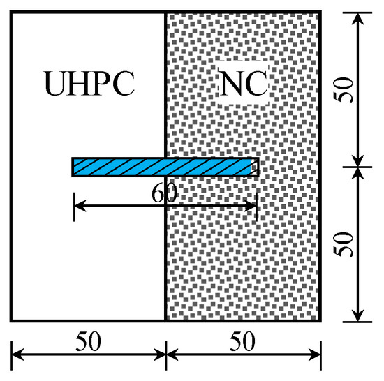
Figure 2.
Specimen design.
The number of salt freeze–thaw cycles in this test was designed as 0, 20, 40, 60, 80, and 100 cycles. The salt solution concentrations employed were 0%, 3.5%, and 5% NaCl solutions. All parameters are detailed in Table 4. The designation is represented as SCX-CNY, where SC denotes the salt solution concentration and CN denotes the number of freeze–thaw cycles. For instance, SC3.5CN60 indicates a salt solution concentration of 3.5% and 60 freeze–thaw cycles. The control group was SC0CN0, representing specimens that were not treated in any way.
Table 4.
Description of test specimens.
Specimens were prepared using a 100 mm × 100 mm × 100 mm standard cubic mould, with the specific preparation steps as follows (Figure 3):
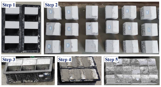
Figure 3.
Specimen fabrication procedure.
- (1)
- The partition was made and placed within the standard concrete formwork.
- (2)
- We poured C50 substrate concrete, conducted formwork removal, then cured it for 28 days.
- (3)
- The demoulded concrete substrate underwent surface preparation for reinforcement planting. Surface laitance and release agent were removed using a wire brush. The prepared specimens were then immersed in clean water.
- (4)
- The immersed concrete substrate was removed to dry until its surface was moisture-free, then placed into the formwork to pour the UHPC.
- (5)
- The specimen was demoulded and naturally cured for 28 days. Subsequently, it underwent immersion in a salt solution.
In accordance with GB/T 50082-2009 [36], freeze–thaw cycling tests were carried out using an IMRD-28 rapid freeze–thaw testing machine. A prepared sodium chloride solution was first injected into the rubber specimen container, followed by the placement of the specimen within the container. The specimen was maintained at a distance of no less than 2 cm from the liquid surface. Each freeze–thaw cycle was completed within 2–4 h, with the thawing period constituting no less than 25% of the total time. The freezing temperature during the cycle was −16 °C, and the thawing temperature was 10 °C. The test termination criteria were either reaching the predetermined number of cycles or the mass loss rate of the test specimen exceeding 5%.
2.3. Testing Methods
A shear tool was designed for interface shear testing. The raw material for the shear test tool was Q235 steel. To eliminate shear slip and inaccurate load measurement caused by shear box deflection, a whole-cut manufacturing process was used. The tool’s design and picture are presented in Figure 4.
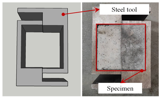
Figure 4.
Shearing tool design.
Direct shear tests were conducted using an MTS electro-hydraulic servo universal testing machine (MTS Systems, Eden Prairie, MN, USA). To measure the relative slip of UHPC-NC interfaces during shear testing, dial gauges were symmetrically positioned on the top surface of the specimen. The test specimen, with dry, ground, and cleaned surfaces, was assembled with the steel tool and positioned on the steel plate at the centre of the testing machine. Rigorous centring was performed to ensure accurate and stable loading.
Preloading was conducted prior to formal loading, with a preload value set at 2 kN to prevent irreversible interface slips. Meanwhile, the test device underwent levelling and centring adjustments, with displacement deviations monitored via dial gauges on both sides. If the deviation exceeded 5%, the device was recalibrated. The loading was formally applied at a displacement control rate of 0.3 mm/min. Crack development and slip at the bond interface were continuously observed and recorded until the specimen underwent complete failure. The shear test loading setup is shown in Figure 5.
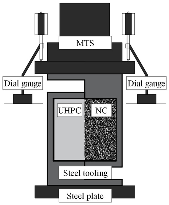
Figure 5.
Arrangement of UHPC-NC shear tests.
3. Apparent Damage and Mass Loss Rate
The variations in appearance of each group specimen were observed following completion of the specified number of freeze–thaw cycles. Subsequently, a comparison with the appearance at the end of the initial curing period was conducted to comprehensively evaluate the impact of freeze–thaw cycles on the appearance of the specimens. Additionally, a precision electronic balance was employed to measure the mass of specimens subjected to freeze–thaw cycles in salt solutions of varying concentrations. The specific procedure is as follows: The mass of the specimen for the specified freeze–thaw cycle test was measured after its surface had been dried. Subsequently, the mass loss rate of the specimen was calculated using Equation (1). If the mass loss reached 5%, the specimen was deemed to have failed.
where ΔMn denotes the specimen’s mass loss rate (%), M0 denotes the specimen’s mass before freeze–thaw cycles (g), and Mn denotes the specimen’s mass after n cycles (g).
3.1. Apparent Damage
The apparent damage modes of the straight shear specimens with embedded reinforcement under salt freeze–thaw cycles are presented in Figure 6, Figure 7 and Figure 8.
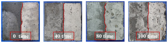
Figure 6.
SC0CNX group specimens.
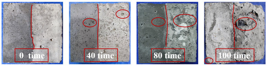
Figure 7.
SC3.5CNX group specimens.
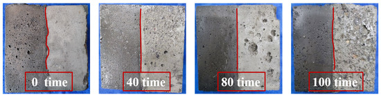
Figure 8.
SC5CNX group specimens.
The development of surface corrosion in each group of specimens under salt freeze–thaw cycles was identical. Taking the most severely eroded SC3.5CNX group specimens as an example, the overall failure process was described. It was observed that the 3.5% salt solution freeze–thaw cycle exhibited the most significant impact on the apparent morphology of the specimens. As the number of freeze–thaw cycles increased, the specimen surface gradually exhibited noticeable pitting and changes in pore structure. Following 40 salt freeze–thaw cycles, surface pitting of the specimens intensified, with obvious spalling occurring in the surface mortar layer and the formation of new failure surfaces. Pores and voids expanded with increasing cycle numbers, and damage progressively propagated towards the interface area. It is worth noting that the changes on the side with UHPC side relatively minor. By the 80th cycle, some steel fibres within the UHPC side began to corrode, with visible rust spots appearing on the surface. The concrete surrounding the fibres underwent localised spalling caused by the volume expansion effect of rust, forming minute cavities. Meanwhile, coarse aggregates in the concrete were partially exposed, with microcracks appearing at the edges. Following 100 freeze–thaw cycles, the corrosion rate of steel fibres within the UHPC accelerated, with exposed sections exhibiting severe fibre corrosion. Only minor spalling occurred at the specimen’s corners. Minor spalling of concrete surrounding corroded fibres was observed. It is noteworthy that the excellent bonding and bridging action between steel fibres and the UHPC substrate effectively suppressed the formation of multi-scale cracks within the concrete. Moreover, the incorporation of steel fibres enhanced the densification of the substrate, thereby improving the structural integrity. In contrast, the coarse aggregates on the NC substrate surface were markedly exposed, with severe edge wear and decreased specimen integrity. Finally, cracks appeared at the UHPC-NC interface, with the mortar structure becoming loose and flaking off upon even slight external contact.
Comparing the apparent damage to specimens subjected to freeze–thaw cycles in three different salt solution concentrations revealed that pure water freeze–thaw caused the least damage. After 100 freeze–thaw cycles, the specimens retained relatively good overall integrity. The surface mortar spalling on the concrete substrate was minimal, and the amount of pitting and voids was significantly lower than in the other two groups. The apparent damage induced by freeze–thaw cycles in a 5% salt solution concentration was greater than that observed in pure water freeze–thaw cycles. The surface corrosion development mode was similar to that in a 3.5% salt solution concentration; however, the extent of damage was slightly less severe. The most obvious damage to the composite specimens was observed under freeze–thaw cycles in a 3.5% salt solution. With the increase in freeze–thaw cycles, the extent of crack opening at the interface of the group became more visible. In summary, the apparent damage levels to the UHPC-NC composite specimens subjected to freeze–thaw cycles in salt solutions of varying concentrations decreased in the following order: 3.5% > 5% > 0% (pure water).
3.2. Mass Loss Rate
The mass loss rate was selected as the quantitative indicator for analysis to provide a more intuitive comparison of the corrosion extent within each sample group. The mass loss rates of specimens subjected to different numbers of freeze–thaw cycles are presented in Table 5 and Figure 9.
Table 5.
Mass loss rate of test specimens (%).
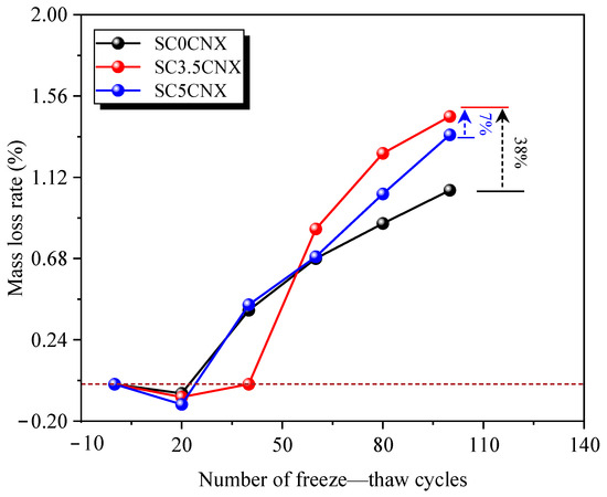
Figure 9.
Mass loss rate under freeze–thaw cycles of the specimens.
It can be observed that the mass loss for each sample group exhibited a trend of initially decreasing and then rapidly increasing with the number of salt freeze–thaw cycles. Combined with the observed damage phenomena, it is evident that the mass loss in the composite specimens was primarily caused by surface spalling of the subgrade concrete. Notably, the slope of the mass-loss-rate–cycle-number curve progressively increased, which indicated that the rate of mass loss accelerated as freeze–thaw cycles continued. This is attributable to the enhanced permeability of the salt solution during the cycling process, which promoted the formation and propagation of microcracks, thereby leading to further spalling of the mortar. When the number of freeze–thaw cycles with salt was lower than 40, the mass loss rates among the three sample groups had little difference. Moreover, an overall increase in mass was observed. The reason can be attributed to the salt solution penetrating the concrete’s pores, where it underwent hydration reactions with the matrix and was accompanied by crystalline separation. This process blocked the pores, which led to an increase in the specimen’s mass. For the freeze–thaw group using clear water, the increase in mass stemmed from the higher porosity and water absorption rate of its substrate concrete, which triggered secondary hydration reactions within the interior or the interface during the freeze–thaw cycles. Following 100 salt freeze–thaw cycles, the mass loss rates for the SC0CN100, SC3.5CN100, and SC5CN100 specimens were 1.05%, 1.45%, and 1.35%, respectively. In particular, the mass loss rate for the SC3.5NC100 group was 38% and 7% higher than those of the SC0CN100 and SC5CN100 groups, respectively. The slopes of the curves also indicated that this group exhibited a higher mass loss rate, demonstrating a tendency towards further accelerated deterioration. Thus, it can be seen that a lower concentration (3.5%) of the salt solution has a stronger damaging effect on this composite specimen.
4. Results of Interface Shear Performance Tests
4.1. Failure Modes
In this study, the primary damage to the specimens occurred within the NC substrate layer, while the UHPC overlay remained largely intact. This phenomenon indicated that the shear strength at the UHPC-NC interface was primarily dominated by the mechanical performance of the NC part. Since the UHPC-NC interface in the specimens was not roughened, the cohesive strength at the interface was low, with shear resistance primarily provided by the dowel action of the reinforcement. However, the reinforcement could only contribute to shear capacity without inhibiting crack propagation. The failure mode of specimens was consequently mainly characterised by failure within the interface transition zone (ITZ). Notably, with increasing salt freeze–thaw cycles, no separation or loosening of the reinforcement within the UHPC side was observed in any specimen. Failure occurred either within the NC substrate or exhibited as reinforcement pull-out. The failure modes primarily included the following three types:
- (1)
- Interface failure between UHPC and NC (Mode A). The three groups of specimens, as shown in Figure 10, were mostly damaged and fractured at the UHPC-NC interface under freeze–thaw cycles with various salt solution concentrations. Cracks associated with this failure mode were primarily concentrated in the interface area, exhibiting relatively smooth fracture surfaces with small amounts of substrate concrete mortar adhering to the UHPC side. During loading, some specimens exhibited brittle failure, characterised by cohesive failure at the UHPC-NC interface. However, due to the presence of the shear reinforcement, the interface maintained a certain shear capacity even after bond failure and exhibited ductile characteristics during subsequent loading. The specific damage progression for this failure mode was that short, fine shear cracks began to form at the UHPC-NC interface when loads reached 67–82% of the ultimate load. As the load increased, these microcracks propagated rapidly. Approaching the ultimate load, a tearing sound was released at the interface, signifying complete debonding of the UHPC-NC interface and marking total interface failure. At this stage, the shear resistance at the interface depended primarily on the reinforcement and the small residual cohesive force between the UHPC and NC. Subsequently, the interface reinforcement gradually detached from the NC substrate under sustained load increase, which eventually resulted in the complete loss of shear resistance at the interface.
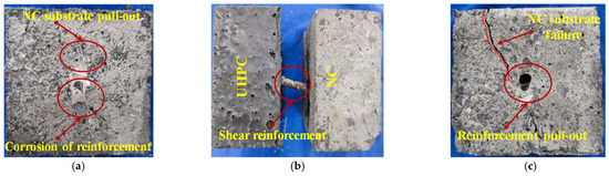 Figure 10. A-type failure mode. (a) UHPC side, (b) shear surface of SC0CN0 group, (c) NC side.
- (2)
- Combined failure of the UHPC-NC interface and NC substrate (Mode B). The failure characteristics exhibit shear failure occurring both at the UHPC-NC interface and within the transition zone between mortar and coarse aggregate within the NC substrate. A substantial amount of NC material was attached to the UHPC surface, and partial fracture of coarse aggregates within the NC could be observed on its lateral face. The damage process for this failure mode proceeded as follows: When the interface was subjected to shear loading, the NC part above the reinforcement was under tension, with primary cracking initiating at the interface. Meanwhile, the NC below the reinforcement was under compression, causing the substrate to gradually crack under pressure. The initial crack propagated along the mortar–aggregate interface transition zone within the NC. As the load increased further, shear failure ultimately occurred both at the UHPC-NC interface and within the NC substrate. This failure mode was commonly observed in specimens subjected to high peak shear loads, indicating high bond strength between the UHPC and NC. The B-type failure mode is illustrated in Figure 11.
 Figure 11. B-type failure mode. (a) UHPC side, (b) shear surface of SC3.5CN0 group, (c) NC side.
- (3)
- NC substrate failure (Mode C). As illustrated in Figure 12, this failure mode can be characterised by shear fracture or damage occurring within the coarse aggregate on the NC side or at the mortar–aggregate interface transition zone, with the overall failure behaviour close to brittle fracture. As the number of salt freeze–thaw cycles increased, the strength of the NC substrate gradually decreased, ultimately falling below the bond strength at the UHPC-NC interface. Hence, the NC substrate was crushed by the shear reinforcement before any significant damage occurred at the interface. The failure process for this mode was as follows: When the ultimate load reached 80–95%, transverse cracks began to form within the NC substrate and propagated rapidly, accompanied by tearing sounds. The interface bond failed at the ultimate load with a loud bang.
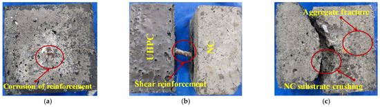 Figure 12. C-type failure mode. (a) UHPC side, (b) shear surface of SC5CN0 group, (c) NC side.
The failure mechanism at the interface of the specimen is presented in Figure 13. Since the UHPC-NC interface was not roughened, its cohesive strength was low, with shear strength primarily provided by the dowel effect of the reinforcement. The introduction of embedded reinforcement significantly influenced crack development under loading, which exhibited a pronounced constraining effect on crack propagation. Notably, the failure mode of the specimens exhibited mostly NC substrate crushing. This is attributable to the fact that the shear strength at the UHPC-NC interface depended increasingly upon the compressive strength of the NC substrate itself as the number of freeze–thaw cycles increased. The freeze–thaw cycles resulted in the gradual deterioration of the NC substrate’s strength. Thus, the ultimate load-bearing capacity of the NC material was reached, and failure occurred before interfacial failure had taken place.
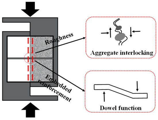
Figure 13.
Failure mechanism of UHPC-NC interface.
4.2. Parametric Analysis
The interfacial shear strength of the UHPC-NC is calculated as per Equation (2):
where f denotes the shear strength at the UHPC-NC interface (MPa), Fτ denotes the shear failure load (kN), and A denotes the effective shear area of the shear surface (mm2).
Two parameters, namely the relative interfacial shear strength (βN) and the interfacial shear strength loss rate (DN), were introduced. Here, βN is the ratio of interfacial shear strength after N salt freeze–thaw cycles to the interfacial shear strength before any cycles, and DN is the loss rate of interfacial shear strength in composite specimens after N salt freeze–thaw cycles. Their equations are as follows:
where τu0 denotes the initial interfacial shear strength of the specimen (MPa), and τuN denotes the interfacial shear strength of the specimen after N salt freeze–thaw cycles (MPa).
The results for the interfacial shear strength and each parameter calculated for each group are presented in Table 6.
Table 6.
Results of shear tests and parameter calculations for UHPC-NC specimens.
The results of the interfacial shear strength tests on specimens subjected to chloride salt erosion and freeze–thaw cycles are presented in Table 6. Under the combined effects of chloride salts and freeze–thaw cycles, the interfacial shear strength of specimens in all groups except the SC5CN20 group was lower than that of the standard specimen. The degradation in interfacial shear strength of the specimens was particularly significant after undergoing 100 freeze–thaw cycles. As the number of freeze–thaw cycles increased, the rate of deterioration in the concrete substrate became much faster than at the interface. The failure mode progressively changed from initial interfacial debonding to failure of NC matrix damage, and degradation of the bond between the interfacial reinforcement and the NC substrate, which manifested as the gradual pulling-out of the reinforcement bars. This phenomenon may be explained by the microcracks generated by freeze–thaw cycles providing pathways for ion migration, enabling greater salt ion penetration into the NC interior. These ions could then undergo chemical reactions with CH or C-S-H gels, producing expansive products. This resulted in damage to the NC substrate while simultaneously reducing the bond strength between the aggregate–mortar interface and the reinforcement. In contrast, UHPC, with its excellent inherent resistance to salt freeze–thaw cycles and extremely low porosity, not only resisted water ingress that could cause freeze–thaw damage but also prevented salt ion penetration. Consequently, it could maintain high bond strength with reinforcement even after multiple salt freeze–thaw cycles. Debonding failure of the interface reinforcement occurred only inside the NC substrate. The 3.5% sodium chloride solution showed the strongest destructiveness in the freeze–thaw cycle, which was due to it having the best permeability and the synergistic effect of crystallisation pressure and frost heave, along with its promotion of corrosion of the steel-concrete interface. In summary, the resistance of the UHPC-NC reinforcement interface to salt-induced freeze–thaw cycles was mainly determined by the strength of the NC substrate.
During the freeze–thaw cycles, the difference in the thermal expansion coefficients between UHPC and NC was one of the key mechanisms that caused interface degradation. Since the thermal expansion coefficient of NC is usually higher than that of UHPC, in the process of repeated cooling (freezing) and heating (melting), the two materials produce uncoordinated thermal expansion and contraction deformation, which leads to significant tensile stress and shear stress concentration in the interface area. This alternating stress aggravates the microcracks caused by the internal pore water pressure generated by the freeze–thaw itself and promotes the initiation and propagation of microcracks in the interface area. With the increase in the number of freeze–thaw cycles, these microcracks are interconnected, which not only directly weakens the bonding strength of the interface but also provides a convenient channel for the invasion of chloride ions. The invaded salt crystallises and expands in the pores of the concrete and rusts the planting bars, which further damages the mechanical bite force and chemical bonding force between the planting bars and the concrete and ultimately leads to a sharp degradation of the interfacial shear performance. Therefore, the difference in thermal expansion and the coupling effect of freeze–thaw and chloride salt lead to the interface failure characterised by the crushing of the NC matrix or the pulling-out of the planted bar.
4.2.1. The Effect of Chloride Salt Concentration
The average shear strength test results for each group of specimens are shown in Figure 14. The degradation rates of shear strength after 20 freeze–thaw cycles were 4%, 7%, and −5% for the SC0CN20, SC3.5CN20, and SC5CN20 groups, respectively. The degradation rates for the SC0CN40, SC3.5CN40, and SC5CN40 groups after 40 cycles were 12%, 14%, and 10%, respectively. The degradation rates for the SC0CN60, SC3.5CN60, and SC5CN60 groups after 60 cycles were 13%, 19%, and 22%, respectively. Following 80 cycles, the degradation rates for the SC0CN80, SC3.5CN80, and SC5CN80 groups were 15%, 32%, and 24%, respectively. The degradation rates for the SC0CN100, SC3.5CN100, and SC5CN100 groups at 100 cycles were 19%, 35%, and 30%, respectively. It is worth noting that the strength loss rate of SC5CN60 group (22%) was slightly higher than that of the SC3.5CN60 group (19%) at 60 freeze–thaw cycles. However, from the overall trend of the whole freeze–thaw process (0 to 100 cycles), the strength loss rate of the SC3.5CNX group was significantly higher than those of the other two groups during most cycles (especially at the two key durability milestones of 80 and 100 cycles). Especially after 100 cycles, the strength loss rate of the SC3.5CN100 group (35%) was significantly higher than that of SC5CN100 group (30%). In summary, the influence of chloride salt concentration on interfacial shear strength could be ranked as follows: 0% < 5% < 3.5%.
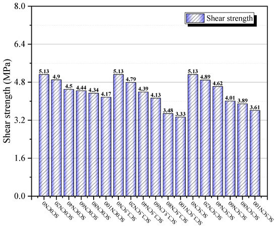
Figure 14.
Average value of interface shear strength.
Comparing the data of each group, the degradation rate of the interfacial shear strength for SC3.5CNX specimens under different cycle numbers was approximately 7–35% higher than the other two groups, with the regularity remaining consistent in different cycle stages. In terms of failure mode, extensive corrosion products were observed in the reinforcement–concrete interface area, which led to a significant reduction in the bond stress between the reinforcement and concrete. Corrosion of reinforcement bars not only reduced their yield strength but also induced stress concentration in severely corroded areas, which eventually led to stress concentration within the NC substrate. Overall, the coupling effect of freeze–thaw cycles with lower-concentration (3.5%) chloride solutions exerted a more significant influence on the shear-bearing capacity at the UHPC-NC interface under varying numbers of freeze–thaw cycles.
4.2.2. The Effect of Salt Freeze–Thaw Cycles
The changes in interfacial shear strength for the SC3.5CNX test group are presented in Figure 15. It can be observed that the shear strength of specimens at the implanted reinforcement interface did not exhibit an upward trend but instead showed a continuous decline. This phenomenon is attributed to the fact that the secondary hydration occurring at the UHPC-NC interface during freeze–thaw cycles enhanced the strength to some extent; however, its improvement in interface performance was less pronounced than the degradation caused by freeze–thaw cycles [29]. Moreover, the stress concentration effect induced by the interface reinforcement within the NC matrix progressively intensified with increasing salt freeze–thaw cycles, further diminishing the shear strength at the interface. For specimens in the SC3.5CNX group, the average interfacial shear strength decreased by 7%, 14%, 19%, 32%, and 35%, respectively, after undergoing 20, 40, 60, 80, and 100 salt freeze–thaw cycles. Notably, the most significant decline in bond strength was observed in this group of specimens after 40 cycles.
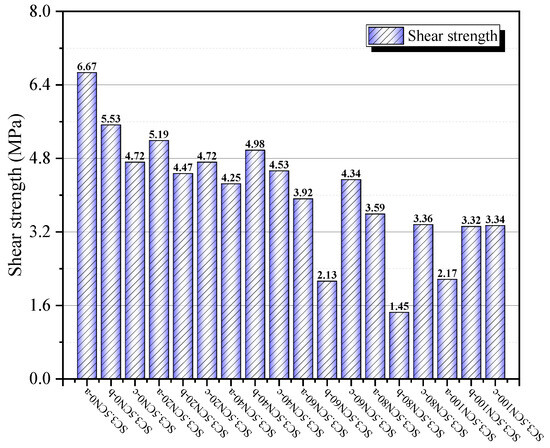
Figure 15.
Interface shear strength of SC3.5CNX group.
These results indicated that salt freeze–thaw cycles could damage the bond interface between the reinforcement and concrete, causing rapid degradation of bond performance and aggravating the dispersion of specimen mechanical behaviour. The reinforcement used in the test was threaded, facilitating the formation of chemical adhesion, mechanical interlocking, and frictional action at the bond interface. During the pouring and curing process, cement paste penetrated the surface of the reinforcement and crystallised, generating chemical adhesion forces. However, the forces produced were relatively weak. Once relative slip between reinforcement and concrete occurred, chemical adhesion gradually failed, with mechanical interlocking and friction becoming the primary mechanisms for shear resistance at the interface.
As illustrated in Figure 16, the loss rate of interfacial shear strength for all three sample groups progressively increased with the number of salt freeze–thaw cycles. Compared to freeze–thaw cycles in pure water, specimens subjected to salt-induced freeze–thaw cycles exhibited steeper curve slopes. This indicated that the coupling effect between salt solutions and freeze–thaw cycles significantly increased the corrosion of shear strength in the specimens. This is attributable to the fact that freeze–thaw cycles intensified internal damage within the concrete. Not only did they induce the formation of microcracks, thereby providing pathways for chloride ion ingress, but they also concurrently caused degradation of the bond between the interface reinforcement and concrete, damage to the concrete substrate, and deterioration of the UHPC-NC interface. The combined effect of these three factors resulted in a continuous decline in the shear strength at the interface.
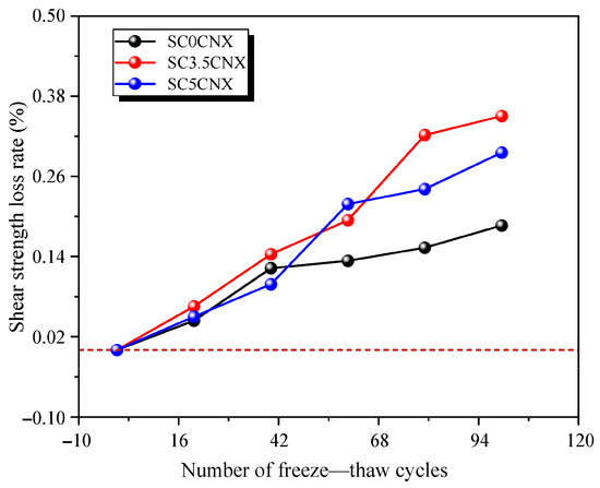
Figure 16.
Interface shear strength loss rate.
4.3. Fitting Model of Mass Loss and Shear Strength Deterioration
To quantitatively evaluate the degradation law of UHPC-NC interface performance under freeze–thaw cycles, a fitting model between mass loss rate and interfacial shear strength loss rate is established in this section, as shown in Figure 17. The experimental data from different working conditions all exhibit a strong linear relationship between these two parameters, with the fitting curves achieving correlation coefficients (R2) exceeding 0.9, indicating statistically significant reliability of the proposed model.
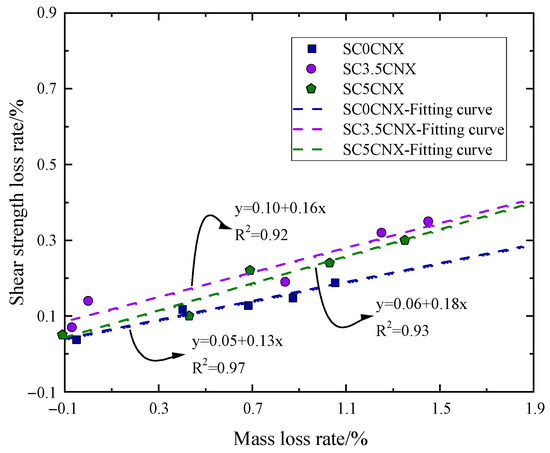
Figure 17.
Fitted model.
From a mechanistic perspective, the deterioration process follows a sequential pattern where physical damage precedes mechanical degradation. The mass loss primarily results from the cyclic freezing and thawing processes that generate crystallisation pressure within the capillary pores, leading to microcrack initiation and propagation along the interfacial transition zone. This damage mechanism is further exacerbated by the differential thermal expansion characteristics between the UHPC and conventional concrete matrices. As freeze–thaw cycles accumulate, these microcracks progressively coalesce and extend toward the surface, resulting in noticeable mortar spalling and interfacial debonding.
The transition from mass loss to strength deterioration occurs through the disruption of load transfer mechanisms at the interface. The developing microcracks and surface deterioration directly compromise the mechanical interlocking effect between the planted steel bar and surrounding concrete, while simultaneously degrading the chemical adhesion properties. This dual degradation mechanism substantially reduces the interface’s capacity to transfer shear stresses, ultimately manifesting as a systematic decline in shear strength proportional to the accumulated mass loss.
4.4. Analysis of Typical Shear Load–Slip Curves
The typical load–slip curves for reinforcement-to-concrete interfaces are divided into two main types based on different failure modes: Firstly, when shear failure occurred at the UHPC-NC interface, the load–slip curve exhibited a distinct ductile stage and a descending stage, corresponding to failure modes A and B. Secondly, when the NC substrate was crushed by the interface reinforcement, the load–slip curve exhibited distinct brittle failure characteristics, corresponding to failure mode C. The typical load–slip curves for both types are presented in Figure 18.
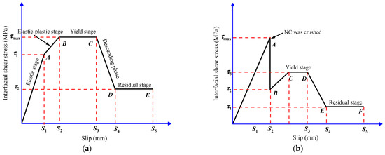
Figure 18.
Typical load–slip curves. (a) I type, (b) II type.
I-type load–slip curves can be divided into five distinct stages: the elastic stage, the elastic–plastic stage, the yield stage, the descending stage, and the residual stage. The critical values corresponding to the five stages were cracking shear strength (τ1), cracking slip (S1), peak shear strength (τmax), peak slip (Smax), residual shear strength (τ2), and residual slip (S4).
During the initial shear stage, stresses and slip values were small, with chemical bonding forces predominating. Specimens remained in the elastic stage. The interface tended to slip as stress increased, but true slip did not occur due to the restraining effect of bonding. In the middle stage of shear failure, the bond strength of the chemical adhesive gradually deteriorated, with friction and the dowel action of the reinforcement becoming the primary shear resistance. The cracks propagated from the UHPC-NC interface to the surface layer of the NC substrate, accompanied by tearing sounds, with slip acceleration (i.e., AB). Subsequently, the crack continued to propagate, causing a dramatic decline in interfacial bond strength. The load was supported solely by friction and the action of the dowels, with stress stabilising while slip increased rapidly (i.e., BC). In the late stage of shear failure, the crack slowly propagated to its ultimate width. The UHPC-NC bond interface completely failed, leaving only the steel dowels to provide residual stress. Ultimately, the reinforcement bent, causing the specimen to lose stability (i.e., CD).
With the increase in salt freeze–thaw cycles, the failure mode of specimens gradually shifted from Type A and Type B to Type C, i.e., the NC substrate was crushed by the interfacial bonded reinforcement. It indicated that the strength of the substrate concrete had fallen below the interfacial bond strength, and the failure mode corresponded to an II-type load–slip curve. During the early shear stage, no cracking occurred at the UHPC-NC interface. When the peak load was reached, the specimen made a loud noise, and a crack was observed to form on the surface of the NC substrate. In the mid-shear stage, load increased gradually due to internal friction within the NC and reinforcement dowel action, while slip increased rapidly (i.e., BC). With further slip development, crack propagation extended to the interface, triggering rapid cracking and entering the descending stage (i.e., DE). The interface ultimately failed completely, relying solely on the reinforcement to provide residual stress until the specimen failed.
With an increasing number of salt freeze–thaw cycles, corrosion of the reinforcement led to a reduction in its yield strength and induced stress concentration at severely corroded regions, further promoting stress concentration within the NC substrate. Moreover, the limited embedment depth of the reinforcement in this experimental programme resulted in an insufficient bond area between the steel and concrete, increasing its susceptibility to debonding. For practical engineering applications, it is recommended to appropriately increase the embedment depth to enhance the interfacial resistance against salt freeze–thaw damage and mitigate stress concentration at the reinforcement’s ends.
5. Conclusions
The main conclusions are as follows:
- (1)
- The direct shear tests on specimens with bonded reinforcement identified three primary failure modes: (I) debonding at the UHPC-NC interface; (II) mixed failure of the UHPC-NC interface and the NC substrate; and (III) crushing of the NC substrate. For reinforcement-bonded interfaces without roughening treatment, the cohesion at the UHPC-NC interface was relatively low, and the interfacial shear strength was primarily provided by the dowel action of the reinforcement. As the number of salt freeze–thaw cycles increased, the strength of the NC substrate deteriorated, often reaching its ultimate bearing capacity before the UHPC-NC interface failed.
- (2)
- Among the tested salt solution concentrations, the freeze–thaw cycles with a 3.5% salt concentration caused the most severe damage to the appearance and morphology of the specimens, while the clear water freeze–thaw group exhibited the least damage. After 100 freeze–thaw cycles, the mass loss rates of groups SC0NC100, SC3.5NC100, and SC5NC100 were 1.05%, 1.45%, and 1.35%, respectively. Group SC3.5NC100 showed a tendency toward accelerated deterioration, indicating that lower salt concentrations have a more significant damaging effect on this composite system.
- (3)
- The interfacial shear strength decreased by 35% after 100 cycles in 3.5% NaCl. Lower salt concentrations had a more pronounced impact on the interfacial shear capacity of UHPC-NC specimens. The interfacial shear strength of the reinforcement-bonded specimens decreased continuously with an increasing number of freeze–thaw cycles. Moreover, the coupled effect of salt solution and freeze–thaw cycles caused greater impairment to the shear resistance compared to clear water freeze–thaw conditions.
- (4)
- The 3.5% salt solution environment caused the most significant damage to the interface, which should be used as a control condition for durability design in practical engineering, and optimising the stress distribution by increasing the buried depth of the planting bar is a potential way to improve the durability of the interface.
Author Contributions
Conceptualization, K.Y.; methodology, H.Y.; formal analysis, H.Y., Y.W. and Z.Z.; investigation, J.L., Z.G. and Y.W.; resources, H.L. and Z.Z.; writing—original draft, J.L. and K.Y.; writing—review and editing, Z.J.; supervision, Z.G. and Z.J.; funding acquisition, H.L. All authors have read and agreed to the published version of the manuscript.
Funding
This research was funded by the Technology Project of Transportation Department of Guizhou Province grant number 2024-122-001.
Data Availability Statement
The original contributions presented in this study are included in the article. Further inquiries can be directed to the corresponding author.
Conflicts of Interest
Authors Jianjun Liu, Hongping Ye and Haigang Li were employed by the company Guizhou Provincial Transportation Planning Survey and Design Institute Co., Ltd. The remaining authors declare that the research was conducted in the absence of any commercial or financial relationships that could be construed as a potential conflict of interest.
References
- Amran, M.; Huang, S.S.; Onaizi, A.M.; Makul, N.; Abdelgader, H.S.; Ozbakkaloglu, T. Recent trends in ultra-high performance concrete (UHPC): Current status, challenges, and future prospects. Constr. Build. Mater. 2022, 352, 129029. [Google Scholar] [CrossRef]
- Du, J.; Meng, W.; Khayat, K.H.; Bao, Y.; Guo, P.; Lyu, Z.; Abu-Obeidah, A.; Nassif, H.; Wang, H. New development of ultra-high-performance concrete (UHPC). Compos. Part B Eng. 2021, 224, 109220. [Google Scholar] [CrossRef]
- Zhang, Z.; Pang, K.; Xu, L.; Zou, Y.; Yang, J.; Wang, C. The bond properties between UHPC and stone under different interface treatment methods. Constr. Build. Mater. 2023, 365, 130092. [Google Scholar] [CrossRef]
- Jiang, J.; Wang, H.; Zhou, Z.; Liang, H.; Zhang, Z.; He, Z.; Zou, Y. Flexural behavior of prefabricated steel-UHPC composite beams with hollow UHPC bridge deck. J. Constr. Steel Res. 2025, 226, 109267. [Google Scholar] [CrossRef]
- Chen, R.; Zhang, Z.; Zou, Y.; Yang, J.; Zhou, J.; Kuang, Y.; Wang, Y. In-situ evaluation on existing RC beam strengthened with GFRP-reinforced UHPC overlay. Constr. Build. Mater. 2024, 429, 136363. [Google Scholar] [CrossRef]
- Yang, J.; Xia, J.; Zhang, Z.; Zhou, J.; Zou, Y.; Wang, Y.; Shen, X. Mesoscopic shear behavior and strength characteristic of UHPC-NC interface considering the combined effect of mechanical interlocking and dowel action. Eng. Fract. Mech. 2024, 307, 110306. [Google Scholar] [CrossRef]
- Wang, J.; Ji, W.; An, M.; Li, W. Fatigue behavior of reinforced UHPC-NC composite beams. Case Stud. Constr. Mater. 2023, 18, e02055. [Google Scholar] [CrossRef]
- Ya, L.; Xinhua, S.; Renyuan, D.; Dongsheng, S.; Songbai, L.; Wei, X.; Xiangguo, W. Study on interfacial performance of ordinary concrete composite structure strengthened by ultra-high performance concrete—A review. Adv. Struct. Eng. 2023, 26, 2797–2813. [Google Scholar] [CrossRef]
- Benedetty, C.A.; dos Santos, V.B.; Krahl, P.A.; Rossi, A.; Silva, F.d.A.; Cardoso, D.C.T.; Martins, C.H. Flexural and shear behavior of steel-UHPC composite beams: A review. Eng. Struct. 2023, 293, 116649. [Google Scholar] [CrossRef]
- Xu, Z.; Qin, F.; Yang, Q.; Peng, X.; Xu, B. A Review of Research on the Interfacial Shear Performance of Ultra-High-Performance Concrete and Normal Concrete Composite Structures. Coatings 2025, 15, 414. [Google Scholar] [CrossRef]
- Zhang, B.; Yu, J.; Chen, W.; Chen, J.; Li, H.; Niu, J. Interface shear failure behavior between normal concrete (NC) and ultra-high-performance concrete (UHPC). Int. J. Concr. Struct. Mater. 2024, 18, 18. [Google Scholar] [CrossRef]
- Huang, Y.; Grünewald, S.; Schlangen, E.; Luković, M. Strengthening of concrete structures with ultra high performance fiber reinforced concrete (UHPFRC): A critical review. Constr. Build. Mater. 2022, 336, 127398. [Google Scholar] [CrossRef]
- Liu, Y.L.; Hong, J.Q.; Deng, J.; Guo, D.; Dai, J.G. Structural performance of RC beams strengthened with hybrid bonded CFRP. J. Build. Eng. 2024, 88, 109178. [Google Scholar] [CrossRef]
- Huang, J.; Hou, W.; Li, Z.; Liu, Y.; Zhang, Y. Enhancing the interfacial bond performance of engineered cementitious composites and concrete. Adv. Struct. Eng. 2024, 27, 1415–1428. [Google Scholar] [CrossRef]
- Zhang, Y.; Zhu, P.; Wang, X.; Wu, J. Shear properties of the interface between ultra-high performance concrete and normal strength concrete. Constr. Build. Mater. 2020, 248, 118455. [Google Scholar] [CrossRef]
- Hachem, Y.; Ezzedine El Dandachy, M.; Khatib, J.M. Physical, mechanical and transfer properties at the steel-concrete interface: A review. Buildings 2023, 13, 886. [Google Scholar] [CrossRef]
- Mansour, W.; Fayed, S. Effect of interfacial surface preparation technique on bond characteristics of both NSC-UHPFRC and NSC-NSC composites. Structures 2021, 29, 147–166. [Google Scholar] [CrossRef]
- Li, X.; Zou, Y.; Dai, X.; Yang, J.; Zhang, Z. Durability of ultra-high-performance concrete in aggressive environments: A comprehensive review of material, interface, structure and enhancement. J. Build. Eng. 2025, 115, 114486. [Google Scholar] [CrossRef]
- Xia, J.; Zhou, J.; Yang, J.; Zhang, Z.; Zou, Y. Damage evolution and residual shear resistance of toughness-improved UHPC-NSC interface under high-stress level of fatigue shear loading. Constr. Build. Mater. 2024, 430, 136403. [Google Scholar] [CrossRef]
- Jiang, Z.; Yu, K.; Zhang, Z.; Leng, J.; Chen, R.; Yang, J.; Zhou, J.; Zou, Y. Effect of casting defects on interfacial shear bonding performance between UHPC and NC substrate subjected to static and cyclic loading. Constr. Build. Mater. 2025, 496, 143736. [Google Scholar] [CrossRef]
- Liu, T.; Charron, J.P. Experimental study on the shear behavior of UHPC-strengthened concrete T-beams. J. Bridge Eng. 2023, 28, 04023064. [Google Scholar] [CrossRef]
- Jiang, Z. Experimental Study on Shear Performance of New and Old Concrete Interface with Grooves and Planted Reinforcement. Ph.D. Thesis, Guangdong University of Technology, Guangdong, China, 2014. [Google Scholar]
- Wang, R.; Zhang, Q.; Li, Y. Deterioration of concrete under the coupling effects of freeze–thaw cycles and other actions: A review. Constr. Build. Mater. 2022, 319, 126045. [Google Scholar] [CrossRef]
- Zheng, X.; Wang, Y.; Zhang, S.; Xu, F.; Zhu, X.; Jiang, X.; Zhou, L.; Shen, Y.; Chen, Q.; Yan, Z.; et al. Research progress of the thermophysical and mechanical properties of concrete subjected to freeze-thaw cycles. Constr. Build. Mater. 2022, 330, 127254. [Google Scholar] [CrossRef]
- Yu, S.; Huang, S.; Li, Y.; Liang, Z. Insights into the frost cracking mechanisms of concrete by using the coupled thermo-hydro-mechanical-damage meshless method. Theor. Appl. Fract. Mech. 2025, 136, 104814. [Google Scholar] [CrossRef]
- Yu, S.; Sun, Z.; Yu, J.; Yang, J.; Zhu, C. An improved meshless method for modeling the mesoscale cracking processes of concrete containing random aggregates and initial defects. Constr. Build. Mater. 2023, 363, 129770. [Google Scholar] [CrossRef]
- Luo, Q.; Zhao, L.; Wu, M. Microstructural damage characterization of NC-UHPC composite under salt freeze-thaw cycles based on ex-situ X-ray computed tomography. Constr. Build. Mater. 2024, 414, 134980. [Google Scholar] [CrossRef]
- Jiang, Z.; He, B.; Zhu, X.; Ren, Q.; Zhang, Y. State-of-the-art review on properties evolution and deterioration mechanism of concrete at cryogenic temperature. Constr. Build. Mater. 2020, 257, 119456. [Google Scholar] [CrossRef]
- Lyu, J.; Feng, S. Investigation of bond shear behaviour of UHPC-NSC and damage prediction model under salt freeze-thaw environment. Eng. Struct. 2025, 330, 119891. [Google Scholar] [CrossRef]
- Zhong, R.; Ai, X.; Pan, M.; Yao, Y.; Cheng, Z.; Peng, X.; Wang, J.; Zhou, W. Durability of micro-cracked UHPC subjected to coupled freeze-thaw and chloride salt attacks. Cem. Concr. Compos. 2024, 148, 105471. [Google Scholar] [CrossRef]
- GB/T 31387-2015; Reactive Powder Concrete. General Administration of Quality Supervision, Inspection and Quarantine: Beijing, China, 2015. (In Chinese)
- T/CBMF 37-2018; Fundamental Characteristics and Test Methods of Ultra-High Performance Concrete. China Building Material Federation: Beijing, China, 2018. (In Chinese)
- GB/T 50081-2019; Standard for Test Methods of Concrete Physical and Mechanical Properties. Ministry of Housing and Urban-Rural Development: Beijing, China, 2019. (In Chinese)
- GB/T 1499.2-2018; Steel for the Reinforcement of Concrete—Part 2: Hot Rolled Ribbed Bars. General Administration of Quality Supervision, Inspection and Quarantine: Beijing, China, 2018. (In Chinese)
- GB/T 50010-2010; Code for Design of Concrete Structures. Ministry of Housing and Urban-Rural Development: Beijing, China, 2010. (In Chinese)
- GB/T 50082-2009; Standard for Test Methods of Long-Term Performance and Durability of Ordinary Concrete. Ministry of Housing and Urban-Rural Development: Beijing, China, 2009. (In Chinese)
Disclaimer/Publisher’s Note: The statements, opinions and data contained in all publications are solely those of the individual author(s) and contributor(s) and not of MDPI and/or the editor(s). MDPI and/or the editor(s) disclaim responsibility for any injury to people or property resulting from any ideas, methods, instructions or products referred to in the content. |
© 2025 by the authors. Licensee MDPI, Basel, Switzerland. This article is an open access article distributed under the terms and conditions of the Creative Commons Attribution (CC BY) license (https://creativecommons.org/licenses/by/4.0/).