Abstract
As a typical steel-concrete composite structure, Concrete-Filled Steel Tubular (CFST) structures utilize the synergistic mechanical advantages of steel and concrete, showing good performance in bearing capacity, ductility and fire resistance, and becoming important in modern buildings. However, CFST structures may suffer hazards like fire, which causes performance degradation affecting subsequent seismic behavior. To study seismic performance of fire-damaged CFST column-steel beam joints, low-cycle repeated loading experiments were carried out on 3 specimens: 2 exposed to different fire temperatures and 1 ambient temperature control. Tests examined hysteretic behavior, ductility, energy dissipation, bearing capacity and stiffness degradation under post-fire axial compression ratios. Results show fire-damaged specimens had similar ductile failure modes to the control. Despite high temperatures, they maintained relatively full hysteretic curves and strong energy dissipation, but with reduced bearing capacity, increased deformation, nonlinear ductility growth, and more significant degradation at higher temperatures.
1. Introduction
With the rapid advancement of prefabricated building systems in China’s construction industrialization, steel structures have been extensively adopted in high-rise and super-tall buildings, primarily owing to their low self-weight, superior load-bearing capacity, and efficiency in reducing construction time. In Concrete-Filled Steel Tubular (CFST) structural systems, beam-column joints are critical force-transmitting components that directly affect the safety and stability of the entire structure []. Thus, research on their seismic performance holds significant engineering value. Wu et al. [,,] investigated the seismic performance of a new type of bolted CFST column-steel beam joint through low-cycle reversed loading tests, revealing that bolted joints possess favorable bearing capacity, deformation capacity, and energy dissipation capacity. Improper connections in prefabricated components can lead to severe damage and significant losses in prefabricated buildings; therefore, connections in prefabricated structures must have good bearing capacity, ductility, and energy dissipation capacity.
In recent years, researchers worldwide have increasingly advanced studies on innovative connection techniques. Liu et al. [] studied a new type of bolted joint between special-shaped CFST columns and steel beams, and finite element analysis showed that elliptical bolt holes and reasonably thick splice plates can effectively improve joint ductility and energy dissipation capacity. Qu et al. [] proposed an assembled composite connection joint between H-shaped steel beams and CFST columns, demonstrating that reasonable optimization of end-plate thickness and bolt diameter can significantly enhance the seismic performance of joints. Wang et al. [] researched the seismic performance of T-shaped CFST column–steel beam joints exposed to low-cycle cyclic actions, finding that adding side plates for reinforcement can notably improve joint ductility and energy dissipation capacity, forming a beam-hinge failure mode that meets seismic design requirements. Xu et al. [] investigated the seismic behavior of CFST column–H-shaped steel beam joints reinforced with external ring stiffeners under cyclic loading. Their findings indicated that a lower column width-to-thickness ratio enhances both joint stiffness and load-bearing capacity, and that T-shaped and cross-shaped joints display different failure modes. Jasim et al. [] studied recycled material-based green concrete-filled C-section steel columns under axial compression. They found that such columns exhibited comparable bearing capacity to conventional concrete-filled columns, and that utilizing double face-to-face sections with steel strip connections improved axial strength by about 3% and delayed buckling. In a related study, Grajçevci et al. [] examined circular steel tubes under axial compression with different boundary conditions, concluding that end constraints critically influence the buckling behavior and ultimate capacity.
Additionally, investigating the post-fire seismic performance of CFST joints plays a vital role in guiding the evaluation and restoration of CFST structures subjected to fire. Under high temperatures, steel strength and stiffness decrease significantly, and concrete experiences spalling, leading to reduced component bearing capacity and overall ductility []. Numerous scholars have conducted extensive research into fire-resistant performance and mechanical performance of steel beam-column joints under or after fire. Kucukler et al. [] established a finite element model to analyze the mechanical response of steel beams and columns under fire conditions, and further proposed a novel fire-resistant design approach for steel beam–column connections at ambient temperature. Nguyen et al. [] investigated the lateral–torsional buckling strength of simply supported beams at elevated temperatures and proposed new correction factors for the Eurocode 3 resistance formulas under such conditions. Chung et al. [] introduced a novel approach for improving the fire resistance of steel beam–column joints by employing fire-resistant steel, which significantly enhanced joint fire performance, structural capacity, and critical temperature. Yang et al. [] researched the temperature distribution, failure modes, and fire resistance of special-shaped CFST column-U-shaped steel-concrete composite beam joints under fire conditions, indicating that lower temperatures in the joint zone help maintain strength and stiffness. They noted that joints may experience beam or column failure with internal force redistribution at high temperatures, and proposed corresponding high-temperature bearing capacity formulas.
Fire causes varying degrees of performance degradation in CFST components, which in turn affects their mechanical performance under subsequent earthquakes. Han et al. [] also researched the residual bearing capacity, stiffness degradation, and seismic performance of CFST columns, beams, and joints after high temperatures or fire, proposing a “time-temperature-load” (t-T-N) path for the entire process from service to fire to earthquake loading, and emphasizing the impact of multi-hazard coupling on joint performance. However, research on key seismic indicators such as hysteretic behavior, ductility, and energy dissipation capacity under post-fire seismic loads—especially in the practical application context of prefabricated structures—remains insufficient. In this context, this paper investigates the behavior of composite joints composed of CFST columns connected to steel beams, conducting low-cycle reversed loading tests to systematically study their post-fire hysteretic behavior, ductility, energy dissipation capacity, and stiffness degradation laws. It further analyzes the effects of factors such as fire exposure and fire temperature on the seismic performance of the joints. The research results aim to provide a reference for the performance evaluation and seismic reinforcement of prefabricated structural joints after fire.
2. Full-Range Fire Test
In this paper, three specimens of composite joints composed of CFST columns and steel beams were designed and fabricated, including two specimens exposed to different fire temperatures and one ambient temperature control specimen. Fire exposure treatment was conducted using a horizontal high-temperature test furnace.
2.1. Specimen Preparation
Three CFST column-H-shaped steel beam joint specimens were designed and fabricated in this study, among which Specimen SJ-1 was the unexposed control specimen, and Specimens SJ-2 and SJ-3 were fire-exposed specimens. The cross-sectional dimensions and physical diagrams of all specimens are shown in Figure 1, with details as follows: The column has a total height of 800 mm, while the beam extends to a total length of 1000 mm. The column cross-section measures 400 mm × 400 mm × 10 mm, with transverse stiffeners installed at the interface between the steel column and the H-shaped steel beam, each having a thickness of 10 mm. In addition, the flange of the H-shaped steel beam is joined to the column stiffeners through full-penetration groove welds.
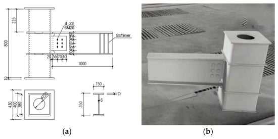
Figure 1.
Schematic Diagram of the H-Shaped Steel Beam Joint Specimen: (a) Schematic diagram; (b) Actual object.
The cross-sectional dimension of the H-shaped steel beam is 350 mm × 150 mm × 6 mm × 12 mm, with a length of 1000 mm. The web of the H-shaped steel beam is fastened to the connecting plate using high-strength bolts. The connecting plate has a cross-sectional dimension of 120 mm × 75 mm × 7 mm. Grade 10.9 M20 friction-type high-strength bolts are used. The core of the steel column is filled with cast-in-place concrete, with a concrete strength grade of C50. All welding operations were performed in the factory, and the weld quality was ensured to comply with the relevant standards []. The primary design parameters are summarized in Table 1.

Table 1.
The primary design parameters of specimens.
2.2. Test Setup
The joint fire exposure test was conducted in a horizontal high-temperature test furnace, with data collected using K-type thermocouples and a temperature data acquisition device. The test setup and specimen placement are shown in Figure 2. A total of 11 K-type high-temperature thermocouples were arranged on each joint specimen, including HGL-1, HGL-2, HGL-3, GWJ-1, GW-2, GWJ-3, GW-4, GNJ-1, GNJ-2, GN-1, and XHNT-1. The positions of these K-type high-temperature thermocouples are shown in Figure 2 below. The furnace heating process strictly followed the ISO-834 standard [] fire curve, with temperature rise controlled by the thermocouples. During the test, specimens SJ-2 and SJ-3 were placed in the furnace for heating, respectively: the target temperature for SJ-2 was 800 °C, and that for SJ-3 was 1000 °C. After reaching the target temperature, the fire exposure treatment was continued for 2 h. Following the completion of testing, the furnace was switched off, and the specimens cooled naturally. The furnace door was opened to observe the damage of the specimens after fire exposure, and the collected temperature data were processed.
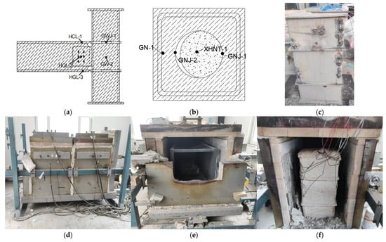
Figure 2.
Layout Diagram of Fire Test Furnace Equipment and K-Type High-Temperature Thermocouple Arrangement: (a) Arrangement of Thermocouples in Joint Specimens; (b) Arrangement of Thermocouples Inside the Steel Column of Specimens; (c) Actual Arrangement of Thermocouples in Joint Specimens; (d) Overall Diagram of Horizontal High-Temperature Test Furnace; (e) Internal Condition of the High-Temperature Test Furnace; (f) Pre-test joint specimens.
2.3. High-Temperature Test
Since the joint specimens were inside the closed high-temperature test furnace, direct observation of phenomena during the fire process was not possible. However, through the furnace observation port, it was observed that after 20 min of heating, water vapor began to emanate from the top of the high-temperature furnace, and the amount of water vapor increased as the temperature rose. After 37 min, the water vapor started to decrease, and no water vapor was emitted after 61 min. At the end of the test, after the fire furnace had sufficiently cooled down, the observation port of the horizontal high-temperature test furnace was opened. It was found that the coating on the outer surface of the joint specimens had cracked and peeled off; the exposed steel showed a darkened color. Since Specimen SJ-3 was heated to a higher temperature, its color was darker, as shown in Figure 3 below.
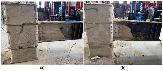
Figure 3.
Actual Condition of Beam-Column Joint Specimens After Fire Exposure: (a) Actual Condition of Specimen SJ-2 After Fire Exposure; (b) Actual Condition of Specimen SJ-3 After Fire Exposure.
After data collection and processing, the average temperature-time curves of each measuring point for Specimens SJ-2 and SJ-3 were obtained, as shown in Figure 4. Observations reveal the following: First, the temperatures at the beam-column measuring points increased over time, and the two curves intersect at the 30 min mark. The average temperature at the measuring points on HGL was higher than that at the measuring points on GZW, GZN, and XHNT. Before 30 min, the maximum average temperature at the HGL measuring points was approximately 60 °C higher than that at the GZW measuring points, and its heating rate was also much higher than that of GZW. As time increased, the difference between the two gradually decreased, so that at 30 min, they were basically consistent. However, after 30 min, the average temperature at the GZW measuring points exceeded that at the HGL measuring points, and the difference between them expanded with the passage of time, with the heating rate of the GZW measuring points surpassing that of the HGL measuring points. Second, the heating rate at the GZW measuring points was much higher than that at the GZN and XHNT measuring points, and this gap widened over time. Finally, compared with the heating rates of the GZW, GZN, and HGL measuring points, the heating rate at the XHNT measuring points was the most gradual. This behavior can be attributed to the material’s thermal conductivity and the heat transfer principle, resulting in a gradual temperature decrease from the exterior to the interior.
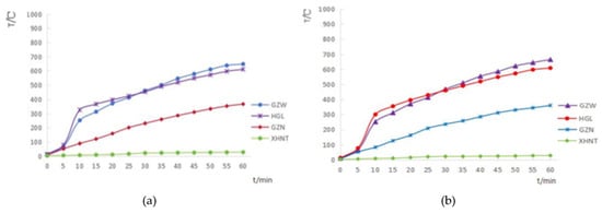
Figure 4.
Average Temperature-Time Curve of Beam-Column Measuring Points: (a) Test Specimen SJ-2; (b) Test Specimen SJ-3.
3. Low-Cycle Repeated Loading Test
3.1. Device and Loading
Low-cycle repeated loading experiments were carried out on the specimens post-fire and at ambient conditions, with the schematic of the loading setup shown in Figure 5. Its boundary conditions were simulated as follows: (1) The base of the column was anchored to the floor-mounted test platform using bolts, providing a fixed boundary condition; (2) Axial pressure of 1000 kN was exerted on the column top through a hydraulic jack. Due to the high strength and stiffness of the entire load-bearing frame, the top of the column could also be regarded as a fixed constraint; (3) Repeated loads were applied to the beam end using an MTS actuator. To prevent torsion at the beam end, three stiffening ribs were welded on both sides of the beam end web to provide lateral constraints. In the joint area, LVDT displacement sensors and strain gauges were deployed on the beam and column to record their deformation and strain throughout the tests. The specific layout of measuring points is shown in the Figure 5.
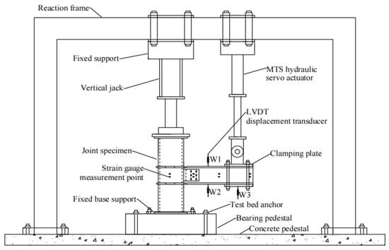
Figure 5.
Schematic diagram of the loading device.
During the loading process, axial pressure was first applied to the column top according to a specific axial compression ratio. Once the axial force reached the designated value, displacement-controlled repeated loads were applied to the beam end. Each loading stage had a displacement of 6 mm, with three reciprocating cycles per stage. The test was stopped when the load dropped to 85% of the maximum load or when the specimen failed. The loading protocol is shown in Figure 6.
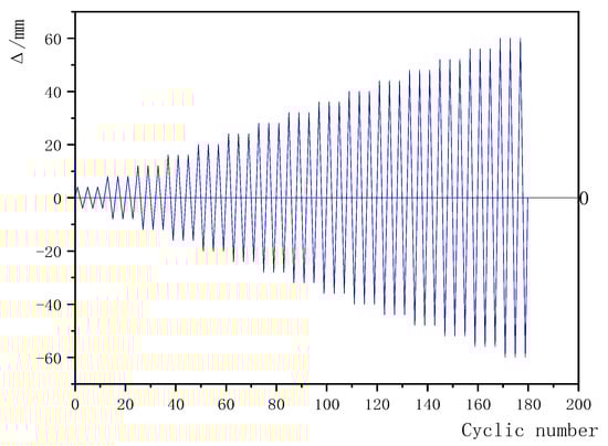
Figure 6.
The loading protocol.
3.2. Test Results
Figure 7a shows the environment of the loading test. During the test, except for the phenomenon of oxide layer peeling off in the fire-exposed specimens, the failure process and failure mode were basically the same as those of the room-temperature unexposed specimens, but there was a slight difference in the failure time.
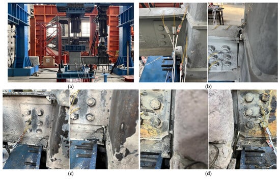
Figure 7.
Test Environment and Conditions: (a) Actual Test Environment; (b) Failure Condition of Specimen SJ-1; (c) Failure Condition of Specimen SJ-2; (d) Failure Condition of Specimen SJ-3.
Figure 7b illustrates the failure mode of Specimen SJ-1. For the unexposed specimen, the load–displacement curve maintained a consistent downward trend, and no significant deformation was observed until the beam-end displacement reached 40 mm, indicating that the specimen remained in the elastic stage. When the displacement increased to 48 mm, cracks initiated at the beam–column joint, accompanied by misalignment and slip of the end plate and web connectors, along with an audible noise. At a beam-end displacement of 56 mm, the cracks propagated through the joint, severe buckling occurred in the steel beam, and the test was immediately terminated.
Figure 7c depicts the failure mode of Specimen SJ-2, which had been exposed to a fire temperature of 800 °C. When the beam-end displacement reached 32 mm, slight torsion occurred at the beam end, accompanied by minor slip at the bolted connection. At a displacement of 40 mm, the anti-corrosion primer on the steel beam cracked and peeled, and small cracks appeared at the beam–column weld joint, gradually propagating thereafter. When the displacement increased to 44 mm, the weld between the beam-end stiffening rib and the web fractured, causing slight web buckling. At a beam-end displacement of 56 mm, the crack in the lower flange at the joint propagated completely, leading to severe damage and prompting immediate termination of the test.
Figure 7d depicts the failure mode of Specimen SJ-3, which had been exposed to a fire temperature of 1000 °C. When the beam-end displacement reached 32 mm, slight buckling occurred at the middle web. At a displacement of 40 mm, severe web buckling developed, accompanied by crack initiation in the lower flange of the joint, which began to propagate. Slip was observed at the bolted connection, and during the third loading cycle, the weld of the lower flange fractured completely. Additional cracks appeared at the lower side of the connection between the steel beam web and the column and gradually propagated. When the beam-end displacement reached 60 mm, the cracks enlarged, severe buckling occurred in the steel beam, and the specimen’s load-bearing capacity decreased to 85% of the peak load, prompting immediate termination of the test.
4. Seismic Performance Analysis
4.1. Hysteretic Behavior
Based on the experimental data, the load–displacement (P–Δ) hysteretic curves of the three specimens were plotted in Figure 8. As shown, the hysteretic curves of all specimens exhibit similar characteristics, presenting a complete shuttle shape. During the initial loading stage, the joints displayed linear hysteretic loops; however, as yielding occurred in the components, the area of the loops increased moderately. Furthermore, throughout the loading process, the loop areas remained nearly constant under the same displacement despite an increasing number of cycles, indicating minimal stiffness degradation in the joints. With further increase in displacement, the hysteretic loops expanded and gradually tilted toward the displacement axis, suggesting a moderate reduction in joint stiffness during energy dissipation.
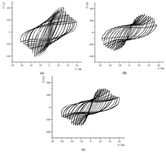
Figure 8.
Hysteretic Curve: (a) Specimen SJ-1; (b) Specimen SJ-2; (c) Specimen SJ-3.
The hysteretic curve of the unexposed Specimen SJ-1 is presented in Figure 8a. During the initial loading stage, the load–displacement curve exhibits a linear increase. Upon unloading, the residual deformation is minimal, resulting in narrow, elongated hysteretic loops with small enclosed areas. As the reciprocating loads increase, residual deformations during unloading gradually grow, and the hysteretic loops progressively open in the displacement direction. Following the attainment of the peak load, the vertical load decreases with increasing displacement, indicating degradation of joint strength and stiffness over successive load cycles. Overall, the hysteretic loops maintain a complete shuttle shape, demonstrating that the specimen possesses substantial plastic deformation capacity and effective energy dissipation capability.
The hysteretic curves of Specimen SJ-2 (exposed to 800 °C fire) and Specimen SJ-3 (exposed to 1000 °C fire) are illustrated in Figure 8b,c. Compared with the hysteretic loops of SJ-1, the hysteretic loops of SJ-2 and SJ-3 exhibit a certain degree of pinching. This “pinching” phenomenon is due to the material damage caused by high-temperature exposure to steel and concrete, which reduces their mechanical properties such as bearing capacity. High temperatures significantly impair the bonding performance at the steel–concrete interface, leading to slip along the interface. The reduction in the bond-friction coefficient results in premature unloading during the tensile path and the formation of open hysteresis loops in the reloading phase under cyclic loading. Under low-cycle repeated loading, this slip will reduce the energy dissipation capacity of the joint during deformation, manifested as the “pinching” of the hysteretic curve. Secondly, high temperature weakens the welds and high-strength bolt connections in the joint area, causing local cracking or slipping, which makes the load transfer path discontinuous. “Sliding” behavior occurs during repeated loading, aggravating the pinching of the hysteretic curve. However, the overall curves are still relatively full, indicating that the joints still have good hysteretic characteristics after fire damage.
4.2. Performance Evolution
Based on the aforementioned test data, the skeleton curves were obtained by plotting and connecting the maximum load points extracted from the hysteretic curves of the three specimens under the first cycle of loading, as shown in Figure 9a. It was found that the skeleton curves of all three specimens exhibited an “S” shape, indicating three distinct stages throughout the loading process: elastic, elastoplastic, and plastic failure. During the initial loading stage, the skeleton curves exhibited a linear increase, indicating that the specimens remained in the elastic state. As the applied load increased, the curves began to display nonlinear behavior. Local buckling developed in the steel beam flanges, and small cracks appeared at the joints, suggesting that the specimens had entered the elastoplastic stage. These cracks gradually propagated and deepened until yielding occurred, after which the joints transitioned into the plastic stage with internal force redistribution. At this stage, the rate of increase in load-bearing capacity slowed and stabilized for a period following the peak load. Continued loading caused further crack propagation at the joints, ultimately leading to final failure, which was characterized by a sharp reduction in the specimens’ load-bearing capacity. Under the same conditions, as the fire temperature increased, the peak load of the specimens diminished, while the displacement at which the peak load occurred increased, and the ascending and descending segments of the skeleton curves became gentler, showing an obvious fire “softening” phenomenon.
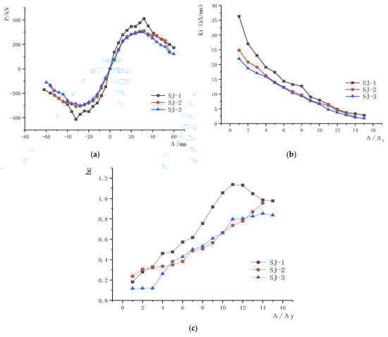
Figure 9.
Specimen Performance Evolution Curve: (a) Skeleton Curve; (b) Stiffness Degradation Curve; (c) Energy Dissipation Curve.
Figure 9b illustrates the stiffness degradation of the three groups of joint specimens during the quasi-static test. As shown, the stiffness of all specimens degraded to varying degrees with increasing displacement, although the overall degradation trends were generally consistent. During the initial loading stage, the steel and concrete components acted largely independently, exhibiting minimal synergistic interaction, which resulted in a high rate of stiffness degradation. As the displacement increased, the interaction between the components intensified, and the rate of stiffness reduction gradually decreased. In particular, when the steel beam buckled, internal forces were redistributed, allowing the joint load to be shared jointly by the beam and column. During the middle and later stages of cyclic loading, the cumulative damage in the joint specimens progressed relatively uniformly, the slope of the stiffness curves decreased, and the degradation trend slowed. Fire exposure and elevated fire temperatures significantly influenced the stiffness of the specimens. Under identical conditions, specimen stiffness decreased progressively with increasing fire temperature. Near failure, however, the stiffness of specimens exposed to different fire temperatures converged. This convergence is attributed to the fact that, at the final stage, the stiffness was predominantly governed by the steel section; with identical steel ratios, the stiffness of all specimens ultimately approached similar values.
Figure 9c presents the relationship curves of the equivalent viscous damping coefficients for the three specimens. As shown, the damping coefficients of all specimens increased with displacement, indicating that the concrete-filled steel tube column–steel beam joints possess good energy dissipation capacity. During the initial loading stage, the reduced stiffness of the fire-exposed specimens resulted in fuller hysteretic loops compared to the room-temperature, unexposed specimen under the same displacement. The equivalent viscous damping coefficient of Specimen SJ-2, exposed to 600 °C, was higher than that of the unexposed Specimen SJ-1. In contrast, for Specimen SJ-3, exposed to 800 °C, severe degradation of material properties led to pronounced “pinching” of the hysteretic loop, resulting in a lower damping coefficient than those of SJ-1 and SJ-2. In the later loading and failure stages, the strength of the fire-exposed specimens deteriorated more rapidly, and the area enclosed by their hysteretic loops at the same displacement was smaller than that of the unexposed specimen. Consequently, the equivalent viscous damping coefficients of SJ-2 and SJ-3 were lower than that of SJ-1, with the reduction becoming more pronounced as the fire exposure temperature increased.
4.3. Seismic Test Coefficient
In accordance with the Technical Specification for Seismic Tests of Buildings [], the stiffness of joint specimens is usually measured by secant stiffness. Secant stiffness refers to the ratio of the sum of absolute values of positive and negative loads to the sum of absolute values of corresponding positive and negative displacements in each loading stage, denoted by Ki. The specific calculation formula is shown in Equation (1).
In this study, the ductility coefficient μ was employed to assess the deformation capacity of the specimens. Its definition is provided in Equation (2) and the corresponding values are summarized in Table 2. The table includes the yield load Py, yield displacement Δy, peak load Pmax, peak displacement Δmax, ultimate load Pu, ultimate displacement Δu, and displacement ductility coefficient μ of each specimen.
Table 2.
Characteristic points of the skeleton curve and ductility coefficient.
Among them, the yield load is determined by the general yield moment method [,]. The load and displacement corresponding to the peak of the skeleton curve are the peak load Pm and peak displacement Δm, respectively. The ultimate load Pu and ultimate displacement Δu refer to the values when the load drops to 85% of the peak load. All data are taken as the average of the absolute values of positive and negative directions during forward and reverse loading.
It can be seen from Table 2 that after exposure to fire, the load-bearing capacity of the specimens decreased, with higher fire temperatures leading to a greater reduction, the greater the load reduction. Compared with the room-temperature unexposed specimen SJ-1, the fire-exposed specimen SJ-2 (exposed to 800 °C) showed a 16.3% decrease in yield load, a 24.4% decrease in peak load, and a 24.4% decrease in ultimate load; for the fire-exposed specimen SJ-3 (exposed to 1000 °C), the yield load decreased by 16.6%, the peak load decreased by 26.7%, and the ultimate load decreased by 26.7%.
The data in Table 2 also shows that the deformation of fire-exposed specimens under load was greater than that of the room-temperature unexposed specimen. Compared with SJ-1, the fire-exposed specimen SJ-2 (800 °C) exhibited a 4.2% increase in yield displacement, a 2.3% increase in peak displacement, and a 24.1% increase in ultimate displacement. For the fire-exposed specimen SJ-3 (1000 °C), the yield displacement increased by 13.7%, the peak displacement increased by 6.4%, and the ultimate displacement increased by 25%. It is evident that the higher the fire temperature, the greater the increase in deformation under corresponding loads.
Additionally, the displacement ductility coefficient of the 800 °C fire-exposed specimen SJ-2 increased by 19.2% compared with the unexposed specimen SJ-1 under the same conditions; however, the displacement ductility coefficient of the 1000 °C fire-exposed specimen SJ-3 decreased by 7.9% compared with the 800 °C fire-exposed specimen SJ-2 under the same conditions. As the fire temperature increased, the ductility coefficient of the concrete-filled steel tube column–steel beam joint initially increased and then decreased, exhibiting a distinct “ductility peak” phenomenon []. This is because after the specimen was exposed to a high temperature of 800 °C, the decrease in the yield strength of the steel led to a delay in yield displacement, and the reduction in the overall stiffness of the specimen allowed for more sufficient plastic development, making the structure “softer” and consequently improving the specimen’s ductility coefficient. However, after exposure to a higher temperature of 1000 °C, the degradation of steel strength intensified, and the plastic potential began to decrease. Although the ultimate displacement still increased slightly, the yield displacement increased at a faster rate, resulting in a decrease in the ductility coefficient.
The trends observed in this study are consistent with previous research. F. Kazemi et al. [] reported stiffness degradation and nonlinear ductility evolution in concrete-timber filled steel tubes (CTFSTs), which is consistent with the post-fire behavior of CFST joints observed in this study. Similarly, Han Y et al. [] found that ductility increases at moderate fire temperatures but decreases at higher levels, confirming the “ductility peak” identified herein. Although only three specimens were tested, the consistency with previous studies supports the reliability of the present conclusions.
The results of this study indicate that joints exposed to 800 °C fire still retain considerable plastic deformation capacity and rehabilitation potential. For moderately fire-damaged joints, strengthening techniques such as attaching carbon fiber-reinforced polymer (FRP) sheets or encasing with steel jackets combined with pressure-injected grout can effectively enhance their load-bearing capacity, stiffness, and energy dissipation capability. The findings provide important support for performance-based seismic design codes in two major aspects: on one hand, the proposed load reduction factors, stiffness degradation models, and ranges of ductility coefficient variation after exposure to different fire temperatures offer quantitative indicators for post-fire seismic performance assessment; on the other hand, the experimental data help define temperature thresholds for “slight”, “moderate”, and “severe” damage levels, thereby facilitating the establishment of more scientific post-fire evaluation and strengthening standards.
In future work, advanced computer vision techniques, such as the DeepLab semantic segmentation model [] and the EfficientNet convolutional neural network [], may be introduced to automatically detect and quantitatively track crack initiation and spalling during cyclic loading, providing a more efficient tool for post-fire damage assessment.
5. Conclusions
In this study, low-cycle repeated loading tests were conducted on three groups of concrete-filled steel tube column–steel beam joints to investigate the effects of varying fire exposure temperatures on their seismic performance. The main conclusions are summarized as follows:
- (1)
- The failure mode of fire-damaged concrete-filled steel tubular column-steel beam joints is basically consistent with that of unexposed specimens at room temperature, all showing ductile failure characteristics such as beam-end buckling and local joint cracking. The hysteretic curves of fire-damaged joints remain relatively full, demonstrating strong energy dissipation capacity, but there is a certain degree of pinching phenomenon, which is more obvious under high temperatures. This indicates that the joints still retain a certain seismic ductility and repair potential after fire, although high temperatures will accelerate the failure process.
- (2)
- The load-bearing capacity of the joints decreases markedly with increasing fire temperature. Compared to the room-temperature specimen, the yield load, peak load, and ultimate load of the fire-exposed specimens are reduced by 16–27%, which can be attributed directly to the deterioration of steel and concrete properties at elevated temperatures. In addition, the initial stiffness of the specimens declines as fire temperature rises. The fire-exposed specimens exhibit lower stiffness during the early loading stage, accompanied by more pronounced degradation. However, when approaching failure, the stiffness of all groups of specimens gradually tends to be consistent, which is ultimately mainly controlled by the section steel.
- (3)
- Fire temperature exerts a significant influence on the ductility of the joints. The deformation capacity (yield displacement, ultimate displacement) of fire-damaged joints generally increases, but the ductility coefficient shows a “first rise then fall” “peak phenomenon”. The ductility coefficient of the specimen subjected to fire exposure at a certain temperature is 19.2% higher than that of the room-temperature specimen, while the ductility coefficient of the specimen at a higher temperature is 7.9% lower than that of the former. This indicates that the improvement effect of ductility begins to weaken after exceeding the critical temperature. However, due to the limited number of specimens, this observation and the resulting trend possess a degree of uncertainty. In future work, we will further validate this phenomenon and confirm the observed trend through testing additional specimens and employing finite element simulation.
Author Contributions
Conceptualization, Y.M. and F.L.; methodology, F.L. and L.Y.; validation, W.M., F.L. and T.X.; formal analysis, L.Y.; data curation, R.Z.; writing—original draft preparation, L.Y.; writing—review and editing, Y.M.; project administration, R.Z. All authors have read and agreed to the published version of the manuscript.
Funding
This research was funded by the Science and Technology Development Project of Jilin Province, grant number 20220203193SF.
Data Availability Statement
Data are contained within the article.
Conflicts of Interest
Author Ran Zheng is employed by the Changchun Institute of Engineering Design and Research Co., Ltd. The remaining authors declare that the research was conducted in the absence of any commercial or financial relationships that could be construed as a potential conflict of interest.
References
- Han, L.H. Concrete Filled Steel Tubular Structures—Theory and Practice, 3rd ed.; Science Press: Beijing, China, 2016. (In Chinese) [Google Scholar]
- Wu, L.-Y.; Chung, L.-L.; Tsai, S.-F.; Shen, T.-J.; Huang, G.-L. Seismic behavior of bolted beam-to-column connections for concrete filled steel tube. J. Constr. Steel Res. 2005, 61, 1387–1410. [Google Scholar] [CrossRef]
- Wu, L.-Y.; Chung, L.-L.; Tsai, S.-F.; Lu, C.-F.; Huang, G.-L. Seismic behavior of bidirectional bolted connections for CFT columns and H-beams. Eng. Struct. 2007, 29, 395–407. [Google Scholar] [CrossRef]
- Wu, C.; Yu, S.; Liu, J.; Chen, G. Development and testing of hybrid precast steel-reinforced concrete column-to-H shape steel beam connections under cyclic loading. Eng. Struct. 2020, 211, 110460. [Google Scholar] [CrossRef]
- Liu, C.-Y.; Qin, J.-H.; Gong, Z.-F.; Wang, H.; Zhou, G.-K. Design and seismic performance analysis of a novel special-shaped steel tube concrete column steel beam joint. Adv. Struct. Eng. 2024, 27, 1922–1944. [Google Scholar] [CrossRef]
- Qu, X.; Xie, Y.; Sun, G.; Liu, Q.; Wang, H. Seismic Behavior of Assembly Joint with CFST Column and H-shaped Steel Beam. KSCE J. Civ. Eng. 2023, 27, 670–683. [Google Scholar] [CrossRef]
- Wang, J.; Li, Q.; Sun, Y.; Zhao, Y.; Niu, Z.; Li, X.; Xu, G. Seismic Behavior of T-Shaped Concrete-Filled Steel Tubular Column to Steel Beam Joints with Side Plates. Adv. Civ. Eng. 2023, 2023, 6698598. [Google Scholar] [CrossRef]
- Xu, P.; Wang, Z.; Mou, B.; Gao, D. Seismic performance of CFST column to steel beam joint with outer annular stiffener. J. Build. Eng. 2022, 54, 104679. [Google Scholar] [CrossRef]
- Jasim, A.; Wong, L.S.; Al-Zand, A.W.; Kong, S.Y. Evaluating axial strength of cold-formed C-section steel columns filled with green high-performance concrete. Civ. Eng. J. 2024, 10, 271–290. [Google Scholar] [CrossRef]
- Grajçevci, F.; Mujaj, A.; Kryeziu, D.; Rrudhani, G.; Shkodrani, N. Experimental and numerical research on the behavior of steel columns with circular hollow cross sections. Civ. Eng. J. 2024, 10, 1577–1588. [Google Scholar] [CrossRef]
- Zhou, H.; Wang, W.; Wang, K.; Xu, L. Mechanical properties deterioration of high strength steels after high temperature exposure. Constr. Build. Mater. 2019, 199, 664–675. [Google Scholar] [CrossRef]
- Kucukler, M. In-plane structural response and design of steel I-section beam columns at elevated temperatures. Structures 2022, 39, 1045–1062. [Google Scholar] [CrossRef]
- Nguyen, X.T.; Park, J.S. Design equations for buckling strength of steel I-beam under non-uniform heating condition. Fire Saf. J. 2022, 127, 103464. [Google Scholar] [CrossRef]
- Chung, H.Y.; Lee, C.H.; Su, W.J.; Lin, R.Z. Application of fire-resistant steel to beam-to-column moment connections at elevated temperatures. J. Constr. Steel Res. 2010, 66, 289–303. [Google Scholar] [CrossRef]
- Yang, W.; Yang, Y.; Liu, F.; Chen, Y.F. Fire research of joint between special-shaped CFST column and U-shaped composite beam. J. Constr. Steel Res. 2024, 213, 108349. [Google Scholar] [CrossRef]
- Han, L.H.; Song, T.Y.; Li, S. Post-fire seismic performance of concrete-filled steel tubular column to steel beam joints with blind-bolted connections: Experiment and simulation. Eng. Struct. 2023, 283, 115892. [Google Scholar] [CrossRef]
- GB 50205-2020; Standardization Administration of the People’s Republic of China. Code for Acceptance of Construction Quality of Steel Structures. China Planning Press: Beijing, China, 2020.
- GB/T 9978.1-2008; Standardization Administration of the People’s Republic of China. Fire Resistance Tests—Elements of Building Construction—Part 1: General Requirements. Standards Press of China: Beijing, China, 2008.
- JGJ/T 101-2015; Ministry of Housing and Urban-Rural Development of the People’s Republic of China. Specifications for Seismic Tests of Buildings. Architecture and Building Press: Beijing, China, 2015.
- Cheng, Y.; Yang, Y.; Li, B.; Liu, J. Research on seismic behavior of special-shaped CFST column to H-section steel beam joint. Adv. Struct. Eng. 2021, 24, 2870–2884. [Google Scholar] [CrossRef]
- Tang, Y.; Wang, Y.; Wu, D.; Liu, Z.; Zhang, H.; Zhu, M.; Chen, Z.; Sun, J.; Wang, X. An experimental investigation and machine learning-based prediction for seismic performance of steel tubular column filled with recycled aggregate concrete. Rev. Adv. Mater. Sci. 2022, 61, 849–872. [Google Scholar] [CrossRef]
- Han, Y.; Bao, Y. Analysis on seismic performance of steel-reinforced concrete-filled circular steel tubular (SRCFST) members subjected to post-fire. Materials 2022, 15, 2294. [Google Scholar] [CrossRef]
- Kazemi, F.; Asgarkhani, N.; Ghanbari-Ghazijahani, T.; Jankowski, R. Ensemble machine learning models for estimating mechanical curves of concrete-timber-filled steel tubes. Eng. Appl. Artif. Intell. 2025, 156, 111234. [Google Scholar] [CrossRef]
- Song, Z.; Zou, S.; Zhou, W.; Huang, Y.; Shao, L.; Yuan, J.; Gou, X.; Jin, W.; Wang, Z.; Chen, X.; et al. Clinically applicable histopathological diagnosis system for gastric cancer detection using deep learning. Nat. Commun. 2020, 11, 4294. [Google Scholar] [CrossRef]
- Kabir, H.; Wu, J.; Dahal, S.; Joo, T.; Garg, N. Automated estimation of cementitious sorptivity via computer vision. Nat. Commun. 2024, 15, 9935. [Google Scholar] [CrossRef] [PubMed]
Disclaimer/Publisher’s Note: The statements, opinions and data contained in all publications are solely those of the individual author(s) and contributor(s) and not of MDPI and/or the editor(s). MDPI and/or the editor(s) disclaim responsibility for any injury to people or property resulting from any ideas, methods, instructions or products referred to in the content. |
© 2025 by the authors. Licensee MDPI, Basel, Switzerland. This article is an open access article distributed under the terms and conditions of the Creative Commons Attribution (CC BY) license (https://creativecommons.org/licenses/by/4.0/).