Abstract
In our investigation, we subjected eleven reinforced concrete beams to a four-point bending system to explore the impact of varying fibre and ferrocement contents on their structural behaviour. These beams, measuring 1.7 m in length, featured a rectangular cross-section with dimensions of 150 mm by 300 mm. Our study focused on three key variables: steel fibre content (at levels of 0.5%, 1%, and 1.5%), glass fibre content (also at 0.5%, 1%, and 1.5%), and ferrocement content (evaluated with one or two layers of welded or expanded wire mesh). Our findings revealed that incorporating fibres with minimal shear reinforcement significantly enhanced the beams’ performance. Specifically: The specimen reinforced with 1.5% steel fibres exhibited the highest ultimate failure load, surpassing the control beam by an impressive 41.87%. The 0.5% glass fibre specimen experienced the least deflection at the ultimate load compared to the control beam. The 1.5% glass fibre specimen demonstrated superior energy absorption compared to the control specimen. Notably, using two layers of welded wire mesh proved most effective in enhancing the ultimate failure load when compared to both the control specimen and other ferrocement-strengthened beams.
1. Introduction
Reinforced concrete beams play a pivotal role in construction due to their robustness and durability. However, a critical concern during the design of these beams is shear failure. Shear failure occurs when the beams experience loads that cause the concrete to crush along planes perpendicular to the beams’ longitudinal axes. This failure mode can lead to sudden and complete structural collapse. To enhance the shear capacity of RC beams, engineers have developed various techniques. Among these, the use of fibres has gained popularity. These fibres can be incorporated into the concrete mix to improve its mechanical properties, particularly shear capacity. There are two main categories of fibres used in RC: Metallic Fibres: Steel fibres, a well-established choice, offer high tensile strength and effectively increase shear capacity. However, they may reduce beam ductility. Non-Metallic Fibres: Stainless steel fibres, in particular, enhance ductility in RC beams. By thoughtfully selecting and incorporating these fibres, engineers can optimize the structural behaviour of RC beams, addressing both strength and ductility considerations.
In recent years, non-metallic fibres—such as polypropylene and glass fibres—have gained significant popularity due to their remarkable corrosion resistance and relatively low cost. These fibres have demonstrated effectiveness in enhancing the shear strength of RC beams, making them an attractive alternative. Moreover, they offer economic advantages compared to metallic fibres. However, it is essential to note that polypropylene fibres exhibit lower tensile strength than their metallic counterparts, which may impact their performance under specific conditions [1,2,3,4,5,6,7,8,9,10]. Additionally, researchers have explored alternative methods to enhance shear performance in RC beams. For instance, in an experimental study [11], the investigators investigated the impact of adding nano-titanium to the concrete mixture on shear behavior.
Numerous empirical investigations have been undertaken to explore the influence of various fibre types on the structural performance of reinforced concrete beams. The introduction of glass fibres into the concrete mix leads to a randomized enhancement in the compressive strength of the material. This is attributed to the retarding effect of fibres on the initiation of the first crack, consequently impeding crack propagation. Furthermore, the inclusion of steel fibres in concrete enhances its tensile strength, ductility, and resistance to shear stresses. Several variations of steel fibres are available, including straight, deformed, end-hooked, crimped, and coned fibres. Steel fibre-reinforced concrete has found extensive utility in the repair of motorway and airport surfaces. Its popularity has soared in construction projects as it provides structural reinforcement for columns, beams, and slabs. In a noteworthy investigation conducted by authors [12], the combined usage of steel fibres and stirrups as transverse reinforcement in reinforced concrete beams was examined. The study involved testing twelve reinforced concrete beams, with variations in fibre content and the quantity of transverse reinforcement. The authors concluded that the optimal improvement in the ductility ratio was achieved by incorporating steel fibres with a content of 1.0% alongside stirrups with diameters of 6 mm and spacing of 200 mm. Notably, the ultimate shear strength exhibited the most substantial improvement of 164% in two beams: the first beam was reinforced with 1.5% steel fibres and stirrups (diameter 6 mm, spacing 200 mm), while the second beam was reinforced with 1.0% steel fibres and stirrups (diameter 6 mm, spacing 100 mm) [12]. Another study [13] investigated four beams, comprising a control beam without steel fibres and three beams with steel fibres added at ratios of 0.5%, 0.8%, and 1%. The researchers concluded that the inclusion of steel fibres improved the shear capacity of the tested beams, transforming the failure mode from brittle to flexural. In a separate experimental study [14], researchers explored the impact of incorporating two types of steel fibres (closed and straight) at varying volume fractions of 0.25%, 0.5%, and 0.75% on the mechanical properties of reinforced concrete. The study revealed that the addition of 0.75% closed steel fibres and straight steel fibres resulted in flexural strength improvements of 43% and 23.8%, respectively. The authors of an experimental study [15] investigated the effect of adding end-hooked steel fibres at percentages of 0.25%, 0.5%, 0.75%, 1%, 1.5%, and 2% to the concrete mix. The researchers determined that the most effective percentage for enhancing the mechanical properties of concrete was 1%. The utilization of glass fibre-reinforced polymer (GFRP) sheets or strips in the shear zone of the reinforced beams demonstrated increased shear strength and ductility compared to control beams without GFRP [16]. Mona K. Ghali conducted an experimental program [17] focusing on the shear strengthening of negative moment regions in reinforced concrete T-beams subjected to a biaxial state of stress resulting from high shear and tensile flexural stresses. The study investigated the most suitable CFRP scheme for reinforcing these regions. In another experimental study [18], the authors examined the effects of incorporating glass fibres at ratios of 0.75% and 1.5% into the concrete mix on the behavior of reinforced concrete beams. Their findings indicated that 1.5% glass fibres yielded the most significant improvement in the concrete’s mechanical properties. Authors of experimental research [19] have explored the impact of incorporating different ratios of glass fibres (0.5%, 0.7%, 0.9%, 1.2%, and 1.5%) as a replacement for fine aggregate on the flexural strength and compressive strength of the concrete mix. They concluded that using 1.5% glass fibres as a fine aggregate replacement resulted in a 30% increase in flexural strength and a 6.4% increase in compressive strength after 28 days compared to specimens without glass fibres. Erfan and El-Sayed [20] demonstrated that the use of ferrocement composite (welded and expanded wire mesh) as shear reinforcement, instead of vertical stirrups, in box section-reinforced concrete beams improved crack patterns, ultimate failure load, and energy absorption. The study revealed that employing three layers of expanded wire mesh achieved the highest increase in ultimate load, amounting to 88.8% compared to specimens reinforced with stirrups. An experimental study [21] examined the utilization of carbon fibre-reinforced polymer (CFRP) sheets as externally bonded reinforcements in reinforced concrete beams. The study showcased shear strength improvements ranging from 22% to 145%, depending on the variables examined. Furthermore, researchers [22] demonstrated that employing GFRP sheets in the reinforcement of reinforced concrete beams increased the ultimate load-carrying capacity and stiffness, contingent upon the number of GFRP layers and their orientation. Equations for the shear design of concrete beams reinforced with glass fibre-reinforced polymer and carbon fibre-reinforced polymer stirrups were formulated by researchers in [23]. In [24,25], the effect of using bars and stirrups made from glass fibre-reinforced polymer in reinforcing concrete beams was examined. The authors [26] further explored the impact of incorporating bars and stirrups made from glass fibre-reinforced polymer on reinforcing concrete beams. An analytical study [27] investigated the shear performance of reinforced concrete beams utilizing a ferrocement composite for shear reinforcement. The results demonstrated that the inclusion of stirrups and ferrocement wire mesh enhanced the shear capacity compared to specimens containing stirrups alone. In the present study, the authors conducted an experimental program to investigate the effects of three different types of non-traditional shear reinforcement, each with varying percentages, on the behaviour of reinforced concrete beams. The obtained results were compared to a control beam reinforced solely with stirrups, as well as different codes of practice.
Research Significance
In this paper, a comprehensive study is conducted to assess the performance of reinforced concrete beams when reinforced with different types of fibres. The aim was to compare the structural behaviour of these strengthened beams, comprising metallic fibres such as steel fibres and ferrocement composite, as well as non-metallic fibres like glass fibres, with that of a control beam under shear load. To ensure a robust analysis, our experimental investigation employed three distinct methods with varying percentages, enabling a comprehensive evaluation. The experimental program involved eleven rectangular reinforced concrete beams measuring 150 mm × 300 mm × 1700 mm. All beams were initially reinforced with steel stirrups. These beams were divided into four groups for testing purposes. The first group served as the control beam without any fibres, while the second group comprised four beams strengthened with different amounts and types of ferrocement wire mesh. The third group consisted of three beams reinforced with varying amounts of glass fibres, and the fourth group included three beams reinforced with diverse quantities of steel fibres. To assess their performance, all beams underwent testing using a four-point loading system. The results of our study demonstrate notable improvements in the ultimate failure load, ductility, and energy absorption of the reinforced concrete beams when incorporating glass fibres, steel fibres, and ferrocement wire mesh. These enhancements signify the effectiveness of these fibre reinforcement methods in enhancing the structural behaviour of the beams under shear load.
2. Experimental Program
2.1. Main Parameters
The parameters included in this experimental investigation are as follows:
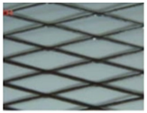
(A) Various configurations of ferrocement wire mesh (one-layer of welded type, two-layers of welded type, one-layer of expanded type, and two-layers of expanded type);
(B) Various quantities of glass fibres (0.5%, 1%, and 1.5%);
(C) Various quantities of steel fibres (0.5%, 1%, and 1.5%).
2.2. Description of Test Specimens
In this study, the experimental program investigated the behaviour of RC beams. The program consisted of eleven simply supported beams, each featuring a rectangular section measuring 150 mm × 300 mm. To reinforce the beams, steel stirrups were utilized uniformly. For testing purposes, the specimens were divided into four distinct groups. The first group comprised a single beam denoted as B1, serving as the control beam without any fibres. In the second group, four beams (B1-2, B2-2, B3-2, and B4-2) were strengthened using different configurations of expanded wire mesh. Specifically, one layer of expanded wire mesh was used for B1-2, two layers for B2-2, one layer of welded wire mesh for B3-2, and two layers of welded wire mesh for B4-2. The third group consisted of three beams (B1-3, B2-3, and B3-3) reinforced with varying percentages of glass fibres: 0.5%, 1%, and 1.5%, respectively. Lastly, the fourth group included three beams (B1-4, B2-4, and B3-4) reinforced with different ratios of steel fibres: 0.5%, 1%, and 1.5%, respectively. To ensure the beams were designed for shear failure, specific reinforcement configurations were employed. For tension reinforcement, four 16 mm diameter bars were positioned in two layers. Compression reinforcement was achieved using two 12 mm diameter bars in one layer. Shear reinforcement was provided through the effective span of the beam using five 6 mm diameter stirrups per meter. For a comprehensive understanding, Figure 1 and Table 1 provide detailed information on the specimens, including their configurations and dimensions. This study aimed to assess the behaviour of these RC beams under various strengthening methods and fibre reinforcements.
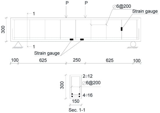
Figure 1.
Beam dimensions.

Table 1.
Experimental program.
2.3. Materials
The concrete mixture design was intended to achieve a target compressive strength of 30 MPa after 28 days of the casting process. To attain this desired strength, specific components were incorporated into the concrete mixture. The mixture comprised 1280 kg/m3 of coarse aggregate with a maximum size of 2 cm, 640 kg/m3 of fine aggregate, 350 kg/m3 of type I Portland cement, and 180 L/m3 of water. The mixing of these concrete components was carried out using a mechanical mixer, ensuring proper homogeneity. To explore the effects of different fibre types, seven concrete mixes were prepared, as presented in Table 2. The fresh properties of these mixes, including slump flow and temperature, were evaluated, and the results can be found in Table 3. In terms of reinforcement, the longitudinal reinforcement steel exhibited a yield strength of 400 MPa, while the shear reinforcement steel (stirrups) had a yield strength of 240 MPa. Two types of ferrocement wire mesh, namely, welded and expanded, were utilized, and their specific characteristics are outlined in Table 4. For the glass fibres incorporated in this study, ECR-glass-type fibres were employed. These fibres possessed a length of 50 mm, a diameter of 0.014 mm, an aspect ratio of 3.57, and a density of 2250 kg/m3. The characteristics of the steel fibres used in the investigation can be found in Table 5. By providing comprehensive details regarding the concrete mixture design and the properties of the various reinforcing materials, this study aimed to explore the impact of different fibre types on the performance of the concrete.
Table 2.
Concrete mix design.
Table 3.
Fresh properties of mixes.
Table 4.
Welded and expanded wire-mesh properties.
Table 5.
Properties of steel fibres.
2.4. Test Setup
The experimental investigation was performed at the National Housing and Building Research Centre in Cairo, Egypt. The study focused on RC beams subjected to a four-point bending system. The loading points were spaced 250 mm apart, and a universal loading machine with a capacity of 500 tons was employed. All specimens were supported using hinged and roller supports, as depicted in Figure 2. Notably, each tested beam adhered to the same shear span-to-effective depth ratio (a/d = 2.5). Before initiating the tests, we applied a thin layer of white paint to both sides of each beam. This facilitated crack observation during testing. The load was incrementally applied as a monotonic static load. At each load increment, we meticulously marked any cracks on the surface of the beams. Additionally, strain gauges were employed to record strain measurements in the flexural reinforcement and stirrups.
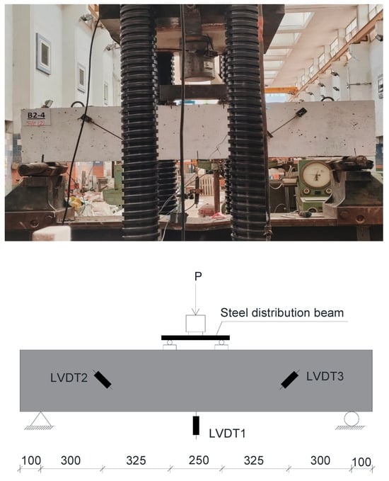
Figure 2.
Typical testing setup of beams.
Instrumentation
A set of three linear variable differential transformers (LVDTs) was utilized to accurately measure the deformations experienced by the tested specimens. These LVDTs were strategically positioned on the concrete surface to ensure precise measurements. To monitor the deflection occurring at the mid-span of the beam, the first LVDT was carefully placed. Additionally, two LVDTs were positioned on the left and right sides of the beam span to measure the strain experienced by the concrete. These placements are depicted in Figure 3, providing valuable insights into the deformation behaviour of the specimens. In addition to the LVDTs, a series of three electrical strain gauges was employed to measure the strains occurring in the flexural steel bars and stirrups. To ensure accurate readings, the surfaces of the bars were meticulously cleaned before attaching the strain gauges. Two internal strain gauges were affixed to the flexural reinforcement steel at the maximum flexural zone, while the third strain gauge was placed on a stirrup at the maximum shear zone. The specific arrangement of these strain gauges can be observed in Figure 4. To safeguard the strain gauges from water and moisture, they were effectively isolated using sito-seal plastic cables. This protective measure ensured the integrity and accuracy of the strain measurements. The terminals of both the strain gauges and LVDTs were connected to an electrical device responsible for recording the readings, as illustrated in Figure 5.
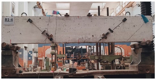
Figure 3.
LVDTs fixing.
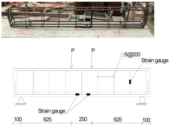
Figure 4.
Arrangement of steel reinforcement and strain gauges.
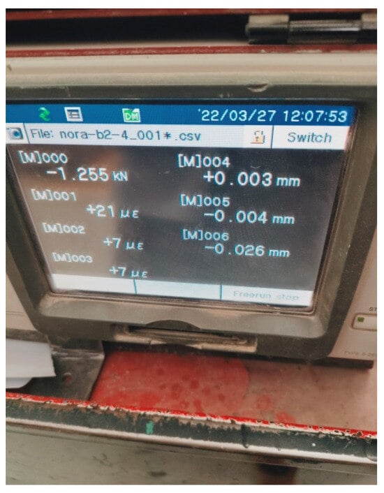
Figure 5.
Electrical monitoring device.
2.5. Test Procedures
Each specimen was loaded until failure. During loading, the cracks were marked on the beam’s surface and their width were measured by using the left and right LVDTs along the beam’s span. At each load increment, photographs were taken to show the crack propagation. The electrical monitoring device recorded the deflection, crack width, strain of longitudinal bars, and shear stirrups. The data were transferred from these devices to the computer and analysed to show the structural behaviour of the tested beams.
2.6. Discussion of the Experimental Test Results
2.6.1. The Failure Mode and the Crack Pattern
The shear response can be explained through the crack pattern and mode of failure of the tested samples. The crack pattern and failure mode of the tested specimens can be identified by observing the development and propagation of cracks as the load increased. The cracks of each of the tested beams were marked during loading of the beams. The crack patterns of all the tested beams are displayed in Figure 6. The general form of the crack propagation of all the tested beams was similar. It can be observed from the figures that fine cracks formed vertically in the flexural zone between the two load points where there was zero shear and maximum flexure. As the load increased, the cracks propagated to the right and left sides of the beam span (in the shear zones). By increasing the load, the width and length of the shear cracks became larger. The destructive cracks of all the tested beams were diagonal and joined the load point and support.
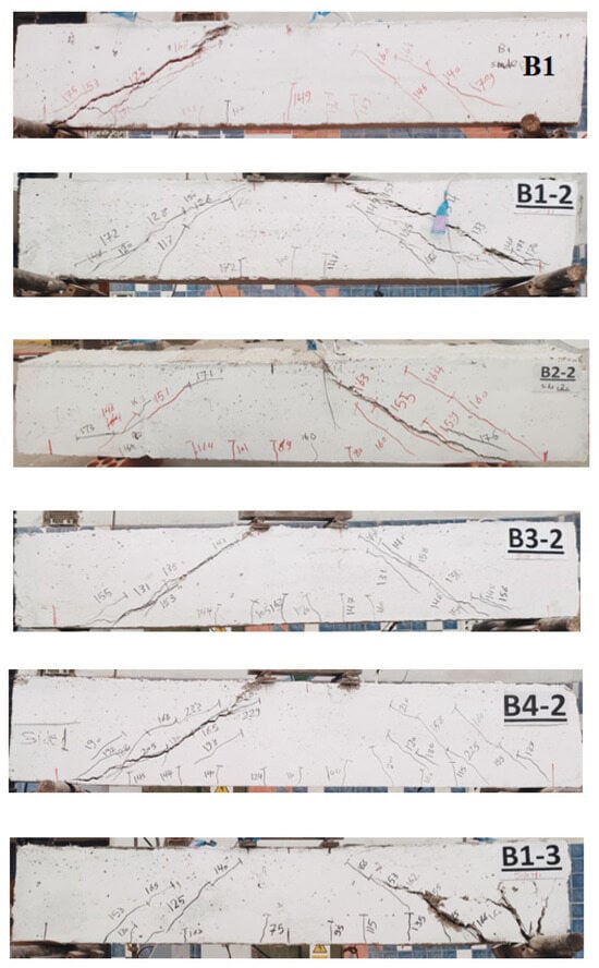
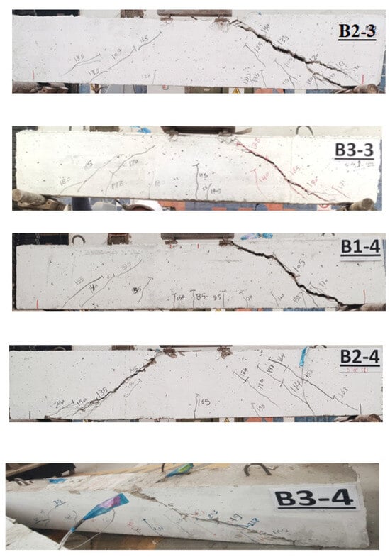
Figure 6.
Crack pattern of all the tested beams.
The failure mode of beams is determined by the formation of cracks during testing. In general, failure modes of beams can be classified into flexural failure, flexure–shear failure, and shear failure. Flexural failure occurs when the crack begins to form vertically at the mid-span of the beam due to the bending moment and propagates towards the top of the beam, as shown in Figure 7. Flexure–shear failure occurs when the combined shear and bending stress exceed the tensile strength of the concrete beam, where the crack begins to form at the mid-span of the beam and propagates in a diagonal direction towards the top end of the beam, as shown in Figure 8. Shear failure occurs when the shear stress exceeds the shear strength of the concrete beam, where the crack propagates diagonally and joins the load point and the support as shown in Figure 9. According to the crack patterns shown in Figure 6, the failure mode of all the tested specimens was shear failure.
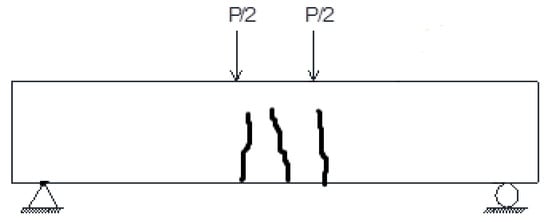
Figure 7.
Flexural crack.
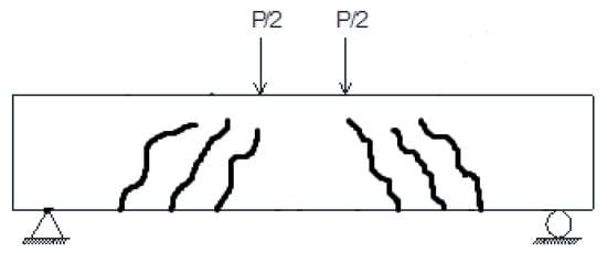
Figure 8.
Flexure–shear crack.
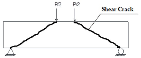
Figure 9.
Shear crack.
Table 6 shows the first crack-load and the deflection at first crack-load of all the specimens. According to Table 6, the specimen B2-4, strengthened with 1% of steel fibres, achieved the maximum first crack load of 110 kN with an enhancement ratio of 10% with respect to the control specimen.
Table 6.
First crack-load and deflection at first crack-load of all specimens.
2.6.2. The Load–Deflection Relationships
The load–deflection relationships of all the experimented beams are displayed in Figure 10a–c. Every curve consists of two branches: the initial branch is almost linear, and the second part is a curve due to the propagation of internal cracks. Using different types of fibre affects the ultimate failure load and the maximum deflection measured at the ultimate load of each specimen.
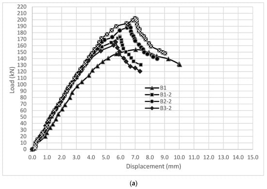
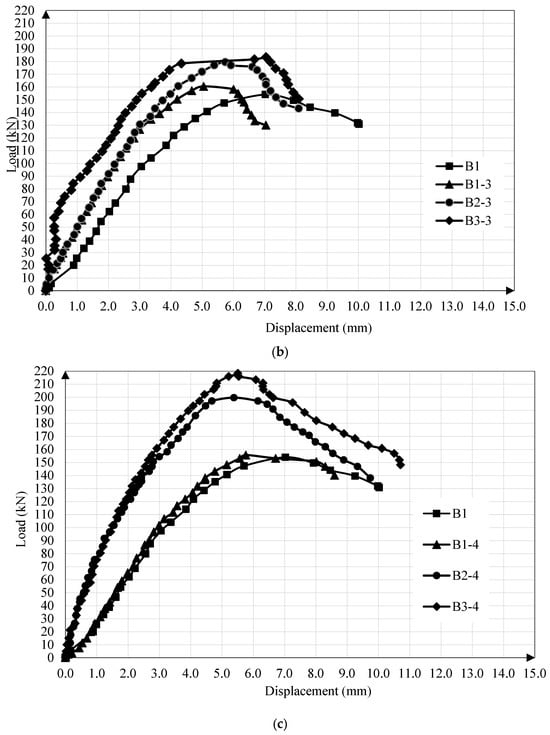
Figure 10.
(a): Relationship between the control beam and beams strengthened using ferrocement wire mesh. (b): Relationship between the control beam and beams strengthened using glass fibres. (c): Relationship between the control beam and beams strengthened using steel fibres.
2.6.3. The Ultimate Failure-Load
The load-carrying capacity of all the specimens depends on the type and the amount of fibre used in the tested specimen. As indicated in Figure 11, the ultimate load for the control beam B1 (without fibres) was 153.920 kN. The second group, which was strengthened with two types of wire mesh (welded and expanded), recorded ultimate loads of 173.943 kN, 192.166 kN, 165.660 kN, and 202.218 kN for B1-2, B2-2, B3-2, and B4-2, respectively. This indicates that the enhancement ratios compared to the control specimen were 13%, 24.85%, 7.63%, and 31.38%, respectively. This ratio was related to the type of ferrocement wire mesh, and the number of layers used in strengthening is shown in Table 1. The ultimate failure loads for the third group, which was strengthened with different amounts of glass fibres in beams B1-3, B2-3, and B3-3, were 160.389 kN, 179.465 kN, and 183.305 kN, with enhancement ratios of 4.20%, 16.60%, and 19.09% for B1-3, B2-3, and B3-3, respectively. For the fourth group, which was strengthened by different percentages of steel fibres, the ultimate loads were 155.620 kN, 199.545 kN, and 218.370 kN with enhancement ratios of 1.10%, 29.64%, and 41.87% for B1-4, B2-4, and B3-4, respectively. As such, B3-4, which contained 1.5% steel fibres, had the maximum enhancement ratio of ultimate load with respect to the control specimen.
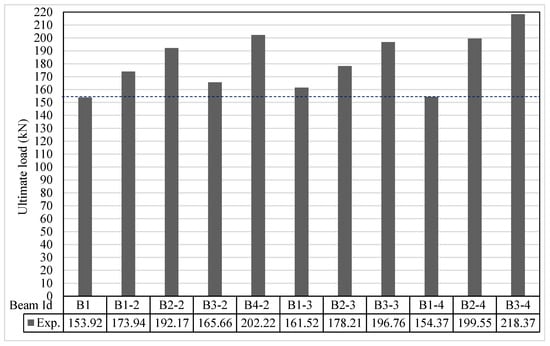
Figure 11.
Ultimate load.
2.6.4. Ultimate Deflection at the Ultimate Load
The load deflection relationships of B1, B1-2, B2-2, B3-2, and B4-2 are shown in Figure 10a. This figure shows that the deflection of B1-2, B2-2, B3-2, and B4-2 decreased by 15.20%, 6.32%, 19.24%, and 0.54%, respectively, compared to the control sample (B1). Figure 10b shows the load deflection relationships of B1, B1-3, B2-3, and B3-3. This figure illustrates that the deflection of B1-3 and B2-3 decreased by 28.12% and 18.27%, respectively, and increased by 0.27% of B3-3 compared to the control beam. The load deflection relationships shown in Figure 10c show that the deflection of B1-4, B2-4, and B3-4 decreased by 18.01%, 23.83%, and 21.59%, respectively, compared to the control sample. As such, the specimen B1-3, which contained 0.5% of glass fibre, has the maximum decrease ratio of deflection compared to the control sample, as shown in Figure 12.
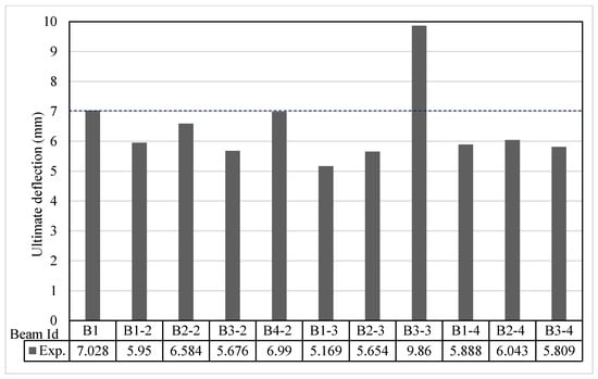
Figure 12.
Ultimate deflection at the ultimate load.
2.6.5. The Ductility Ratio
Specimen B3-3 strengthened with 1.5% of glass fibres recorded the maximum ductility ratio of 26.49 with a maximum enhancement percentage assessed to the control sample (B1). The ductility ratios for all tested samples are shown in Figure 13.
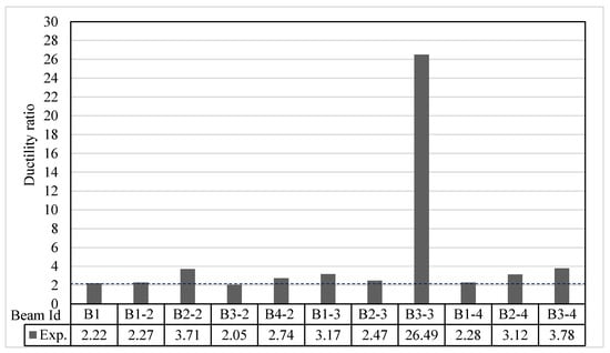
Figure 13.
Ductility ratio.
2.6.6. The Energy Absorption
The energy absorption is calculated as the entire area under the load deflection curve up to the ultimate failure load. The specimen B3-3 had the maximum value of energy absorption, 983.6 kN.mm, with a maximum enhancement percentage compared to the control beam. The values of the energy absorption for all tested samples are indicated in Figure 14.

Figure 14.
Energy absorption.
3. Building Code Predictions
This section presents a comprehensive comparison between the shear capacity of the tested specimens obtained through experimentation and the shear capacity predicted by various design provisions incorporated in different codes. The codes considered for this comparison are the Egyptian Code of Practice (ECP-203-2020) [28], the American Concrete Institute Code (ACI-318-2019) [29], and the Model Code 2010 [30]. These codes provide guidelines for determining the design shear load, which is calculated as the product of the design shear capacity of the concrete and the area of the critical shear section. The location of the critical section for shear evaluation in beams varies depending on the specific code. As per the ECP code, the critical section extends from the face of the support up to half of the effective beam depth (d/2). On the other hand, the ACI code designates the critical section for shear from the support face up to the effective beam depth (d). To assess the effectiveness of these design provisions, we compare the experimental shear capacity of the tested specimens against the predicted shear capacity as per ECP-203-2020 [28], ACI-318-2019 [29], and the Model Code 2010 [30]. The results of this comparison are presented in Table 7, offering a comprehensive overview of the performance of the different codes in predicting shear capacity.
Table 7.
Comparing test findings to building code projections.
According to Table 7, the code predictions for shear capacity are dependent on the type of fibres or meshes used for shear strengthening in the beams.
3.1. Shear Strength of Beams Strengthened with Ferrocement Wire Mesh, Vferro-cement
The ECP and ACI do not give provisions to calculate the shear strength of ferro-cement wire mesh, group 2. As such, the wire mesh is considered as a stirrup of an equivalent diameter to the number of wires of mesh through the spacing between the shear stirrups. The shear capacity is calculated as:
where:
V: ultimate shear capacity;
: shear strength of concrete;
: shear strength of stirrups;
: shear capacity of expanded wire-mesh.
In Table 8, the mean predicted-to-experimental shear capacity ratio was 0.589, with a C.O.V of 3.23%, and 0.527, with a C.O.V of 4.55% with respect to the ECP and ACI, respectively. Thus, both the ECP and ACI provisions resulted in acceptable predictions of the shear strength for this type of strengthening.
Table 8.
Comparing test findings to building code projections (specimens strengthened with ferrocement).
3.2. Shear Strength of Glass Fibre-Strengthed Beams
For specimens with glass fibres in group 3, the ECP and ACI do not include provisions to evaluate the shear strength for glass fibre-reinforced concrete. Since the shear strength relies mostly on the compressive strength, the glass fibre RC shear strength was calculated by employing the compressive strength of concrete, which was obtained from the glass fibre RC cubes during testing.
Table 9 shows the average predicted–to-experimental shear capacity ratio of 0.520 with a C.O.V of 6.50%, 0.474 with a C.O.V of 6.33%, and 0.565 with a C.O.V of 5.13% with respect to the ECP and ACI. Table 9 shows that the ECP and ACI resulted in acceptable forecasts of shear strength.
Table 9.
Comparing test findings to building code projections (specimens strengthened with glass fibres).
3.3. Shear Strength of Steel Fibre-Strengthed Beams
For specimens with steel fibres in group 4, the ECP does not give provisions to calculate the shear capacity of steel fibre-reinforced concrete, but the shear strength of steel fibre-reinforced concrete is calculated using compressive strength of concrete, obtained from the steel fibre RC cubes during testing. The ACI [29] and Model code, 2010 [30], include provisions to calculate the shear capacity of steel fibre RC beams (Equations (1) and (2)).
where:
: shear resistance of stirrups;
: shear capacity of SFRC beams.
where:
k = 1 + ;
: ;
: tensile strength of steel fibre;
: tensile strength of concrete;
: compressive strength of concrete.
Table 10 shows the mean predicted-to-experimental ratio as 0.502, with a C.O.V of 17.33%, and 1.075, with a C.O.V of 9.11%, with respect to the ECP and ACI, respectively. According to Table 10, the ECP prediction is acceptable, while the ACI predictions overestimated the strength of three specimens strengthened with steel fibres.
Table 10.
Comparing test findings to building code projections (specimens strengthened with steel fibres).
4. Comparison with Previous Reported Work
4.1. Provisions Proposed by Ghugal and Deshmukh [31]
Ghugal and Deshmukh included Equations (3)–(5) to compute the shear capacity of glass fibre RC beams without stirrups. A second term (Equation (6)) must be added to Equation (5) when stirrups are included, as in Russo and Puleri [32]. Table 11 shows a comparison between the obtained experimental shear capacity and the theoretical shear capacity for the specimens strengthened with glass fibres, according to these research works.
where:
: shear strength of glass fibre RC beams, MPa;
: volume fraction of glass fibre;
: modulus of elasticity of concrete = 5 (GPa);
: modulus of elasticity of glass fibre, (GPa);
: flexural strength of beam.
where:
x = + 250 ;
= concrete cube compressive strength, MPa;
a/d = shear span to depth ratio;
ρw = stirrups ratio = (Aw/bs);
fyw = yield strength of stirrups, MPa.
Table 11.
Comparison between the experimental shear capacity and theoretical shear capacity according to [31,32].
Table 11.
Comparison between the experimental shear capacity and theoretical shear capacity according to [31,32].
| Specimens | Description | (KN) | (KN) | |
|---|---|---|---|---|
| B1-3 | 0.5% glass fibre | 80.19 | 47.974 | 0.598 |
| B2-3 | 1.0% glass fibre | 89.82 | 49.091 | 0.551 |
| B3-3 | 1.5% glass fibre | 91.65 | 50.041 | 0.546 |
| Mean value | 0.565 | |||
| S.D. | 0.029 | |||
| C.O.V % | 5.13 | |||
According to Table 11, it should be noted that provisions in [28,29] resulted in acceptable predictions of the shear capacity for specimens strengthened with glass fibres.
4.2. Provisions Proposed by Naryanan and Darwish [33]
Table 12 gives the relationship between the experimental shear capacity and theoretical shear capacity, estimated as per this research work for the specimens strengthened with steel fibres. According to Table 12, provisions in this research work resulted in acceptable predictions of the shear capacity for specimens strengthened with steel fibres.
Table 12.
Difference between the experimental shear load and computed shear load, as stated by [33].
4.3. Provisions Proposed by Ashour, Hasanain, and Wafa [34]
Table 13 exhibits an assessment of the experimental shear capacity and the theoretical shear capacity for the specimens strengthened with steel fibres calculated according to this research investigation. According to Table 13, the theoretical results overestimated the shear capacity for two specimens, as the mean predicated-to-experimental shear capacity ratio was 1.02, with a coefficient of variation (C.O.V) of 4.22%.
Table 13.
Difference between the experimental shear load and computed shear load, as stated by [34].
4.4. Provisions Proposed by Al-Taan and Al-Feel in [35]
Table 14 shows a comparison between the shear capacity obtained from the test results and the theoretical shear capacity for specimens strengthened with steel fibres, which were calculated according to this research work. Table 14 shows that the provisions in this research overestimated the experimental results of the shear capacity.
Table 14.
Difference between the experimental shear load and computed shear load, as stated by [35].
5. Conclusions
Depending on the investigational results obtained in the current research work and the comparison between these results and the various codes of practice, in addition to various research works reported in the literature, the following conclusions can be drawn:
- The usage of 1.5% steel fibres is considered as the best for enhancing the ultimate load by 41.87% with respect to the control beam, but using 1.0% of steel fibres achieved the maximum value of load at first cracking, with an enhancement ratio of 10% with respect to the control beam.
- Using 1.5% of glass fibres achieved the maximum ductility ratio and energy absorption. The enhancement of energy absorption with respect to the control specimen was 47.94%.
- Incorporating two layers of expanded wire mesh enhanced the failure load, ductility ratio, and energy absorption by 10.48%, 63.44%, and 30.34%, respectively, with respect to the specimen strengthened with one layer of expanded wire mesh.
- Using two-layers of welded wire mesh enhanced the failure load, ductility ratio and energy absorption by 22.04%, 33.66% and 54.84%, respectively with respect to the specimen strengthened with a single layer of welded wire-mesh.
- Using two layers of welded wire mesh is better than using two layers of expanded wire mesh for improving the ultimate failure load.
- Using 1.5% of steel fibres is better than using 1.5% of glass fibres for increasing the ultimate load.
- The ECP and ACI provisions resulted in acceptable predictions of the shear capacity of specimens strengthened with ferro-cement wire mesh, where the mean predicted-to-experimental shear capacity ratios were 0.589 and 0.527 for ECP and ACI, respectively.
- The average predicted-to-experimental shear capacity ratios of specimens strengthened with glass fibres were 0.520, 0.474, and 0.565 with respect to the ECP, ACI, and reported research work [31,32], respectively. This shows that the ECP, the ACI, and the previous research work resulted in acceptable predictions of shear capacity for this type of strengthening.
- The mean predicted-to-experimental ratios for specimens strengthened with steel fibres were 0.502, 1.075, 0.736, 1.02, and 1.18 with respect to the ECP, ACI, and reported research work [33,34,35]. This means that the ACI predictions and provisions in these studies [34,35] overestimated the shear capacity for the beams strengthened with steel fibres, but the ECP predictions and provisions in this research [33] resulted in acceptable predictions of the shear strength of these beams.
- It is suggested that the results obtained from this research work, together with similar research works, should be implemented in the various codes of practice for beams strengthened with steel fibres under shear loading.
Author Contributions
Conceptualization, T.A.E.-S. and N.K.; Methodology, M.K.N.G., T.A.E.-S. and A.S.; Software, N.K.; Validation, T.A.E.-S. and N.K.; Formal analysis, N.K.; Investigation, T.A.E.-S. and N.K.; Resources, N.K.; Data curation, N.K.; Writing—original draft, T.A.E.-S. and N.K.; Writing—review & editing, M.K.N.G., T.A.E.-S., A.S. and N.K.; Supervision, M.K.N.G., T.A.E.-S. and A.S. All authors have read and agreed to the published version of the manuscript.
Funding
This research received no external funding.
Data Availability Statement
Data is contained within the article.
Conflicts of Interest
The authors declare no conflict of interest.
References
- Ibrahim, S.S.; Kandasamy, S.; Subashchandrabose, R.; Baskar, S.; Madhava, V. Performance enhancement of externally bonded reinforced concrete beams with 3D hooked-end steel fibres. Case Stud. Constr. Mater. 2022, 17, e01181. [Google Scholar]
- Abdullah, Q.N.; Abdulla, A.I. Flexural behavior of hollow self compacted mortar ferrocement beam reinforced by GFRP bars. Case Stud. Constr. Mater. 2022, 17, e01556. [Google Scholar] [CrossRef]
- Gideon, A.M.; Milan, R. Effects of nitinol on the ductile performance of ultra high ductility fibre reinforced cementitious composite. Case Stud. Constr. Mater. 2021, 15, e00582. [Google Scholar] [CrossRef]
- Zhang, Z.; Abbas, E.M.; Wang, Y.; Yan, W.; Cai, X.; Yao, S.; Tang, R.; Cao, D.; Lu, W.; Ge, W. Experimental study on flexural behavior of the BFRC-concrete composite beams. Case Stud. Constr. Mater. 2021, 15, e00738. [Google Scholar] [CrossRef]
- Hasnat, A.; Das, T.; Ahsan, R.; Alam, A.T.; Ahmed, H. In-plane cyclic response of unreinforced masonry walls retrofitted with ferrocement. Case Stud. Constr. Mater. 2022, 17, e01630. [Google Scholar] [CrossRef]
- Nguyen, T.K.; Nguyen, N.T. Finite element investigation of the shear performance of corroded RC deep beams without shear reinforcement. Case Stud. Constr. Mater. 2021, 15, e00757. [Google Scholar] [CrossRef]
- Murad, Y.; Abdel-Jabbar, H. Shear behavior of RC beams prepared with basalt and polypropylene fibers. Case Stud. Constr. Mater. 2022, 16, e00835. [Google Scholar] [CrossRef]
- Akkaya, H.C.; Aydemir, C.; Arslan, G. Investigation on shear behavior of reinforced concrete deep beams without shear reinforcement strengthened with fiber reinforced polymers. Case Stud. Constr. Mater. 2022, 17, e01392. [Google Scholar] [CrossRef]
- Jianbing, Y.; Yufeng, X.; Saijie, L.; Zhiqiang, X. Experimental study on shear performance of basalt fiber concrete beams without web reinforcement. Case Stud. Constr. Mater. 2022, 17, e01602. [Google Scholar] [CrossRef]
- Askar, M.K.; Hassan, A.F.; Al-Kamaki, Y.S. Flexural and shear strengthening of reinforced concrete beams using FRP composites: A state of the art. Case Stud. Constr. Mater. 2022, 17, e01189. [Google Scholar] [CrossRef]
- Alobaidy, Q.N.A.; Abdulla, A.I.; Al-Mashaykhi, M. Shear Behavior of Hollow Ferrocement Beam Reinforced by Steel and Fiberglass Meshes: Shear Behavior. Tikrit J. Eng. Sci. 2022, 29, 27–39. [Google Scholar] [CrossRef]
- Sarhat, S.R.; Abdul-Ahad, R.B. The combined use of steel fibers and stirrups as shear reinforcement in reinforced concrete beams. Spec. Publ. 2006, 235, 269–282. [Google Scholar]
- Gomes, L.D.D.S.; Oliveira, D.R.C.D.; Moraes Neto, B.N.D.; Medeiros, A.B.D.; Macedo, A.N.; Silva, F.A.C. Experimental analysis of the efficiency of steel fibers on shear strength of beams. Lat. Am. J. Solids Struct. 2018, 15, e86. [Google Scholar] [CrossRef]
- Iqbal, S.; Ali, I.; Room, S.; Khan, S.A.; Ali, A. Enhanced mechanical properties of fiber reinforced concrete using closed steel fibers. Mater. Struct. 2019, 52, 56. [Google Scholar] [CrossRef]
- Mohod, M.V. Performance of steel fiber reinforced concrete. Int. J. Eng. Sci. 2012, 1, 1–4. [Google Scholar]
- Panda, K.C.; Barai, S.V.; Bhattacharyya, S.K. Shear Strengthening of T-beam with GFRP. In Springer Transactions in Civil and Environmental Engineering; Springer: Berlin/Heidelberg, Germany, 2018. [Google Scholar]
- GHALI Mona Kamal, N. Behavior of Negative Moment Regions in Reinforced Concrete T-Beams Strengthened in Shear by CFRP. Master Thesis, Scientific Bulletin, Faculty of Engineering, Ain Shams University, Cairo, Egypt, June 2007. [Google Scholar]
- Ata, E.S.S.; Moustaf, O. Experimental analysis of RC beam strengthened with discrete glass fiber. Facta Univ.-Ser. Archit. Civ. Eng. 2011, 9, 205–215. [Google Scholar] [CrossRef]
- Murthy, Y.I.; Sharda, A.; Jain, G. Performance of glass fiber reinforced concrete. Int. J. Eng. Innov. Technol. 2012, 1, 246–248. [Google Scholar]
- El-Sayed, T.A.; Erfan, A.M. Improving shear strength of beams using ferrocement composite. Constr. Build. Mater. 2018, 172, 608–617. [Google Scholar] [CrossRef]
- Khalifa, A.; Belarbi, A.; Nanni, A. Shear performance of RC members strengthened with externally bonded FRP wraps. In Proceedings of the Twelfth World Conference on Earthquake, Auckland, New Zealand, 30 January–4 February 2000. [Google Scholar]
- Sawant, S.G.; Sawant, A.B.; Kumthekar, M.B. Strengthening of RCC beam-using different glass fiber. Int. J. Inven. Eng. Sci. 2013, 1, 1–8. [Google Scholar]
- Shehata, E.; Morphy, R.; Rizkalla, S. Fibre reinforced polymer shear reinforcement for concrete members: Behaviour and design guidelines. Can. J. Civ. Eng. 2000, 27, 859–872. [Google Scholar] [CrossRef]
- Hamid, N.A.A.; Thamrin, R.; Ibrahim, A. Shear capacity of non-metallic (FRP) reinforced concrete beams with stirrups. Int. J. Eng. Technol. 2013, 5, 593. [Google Scholar] [CrossRef]
- Kotynia, R.; Kaszubska, M.; Barros, J.A. Shear Behavior of Steel or GFRP Reinforced Concrete Beams without Stirrups. In High Tech Concrete: Where Technology and Engineering Meet; Springer: Cham, Switzerland, 2018; pp. 769–777. [Google Scholar]
- Deng, Y.; Ma, F.; Zhang, H.; Wong, S.H.; Pankaj, P.; Zhu, L.; Ding, L.; Bahadori-Jahromi, A. Experimental study on shear performance of RC beams strengthened with NSM CFRP prestressed concrete prisms. Eng. Struct. 2021, 235, 112004. [Google Scholar] [CrossRef]
- Megarsa, E.; Kenea, G. Numerical investigation on shear performance of reinforced concrete beam by using ferrocement composite. Math. Probl. Eng. 2022, 2022, 5984177. [Google Scholar] [CrossRef]
- E.C.P. 203/2020. Egyptian Code of Practice: Design and Construction for Reinforced Concrete Structures, Cairo, Egypt. 2020. Available online: https://www.scirp.org/reference/referencespapers?referenceid=52937 (accessed on 15 May 2024).
- ACI Committee 3. Building Code Requirements for Structural Concrete (ACI 318-19) and Commentary; American Concrete Institute: Indianapolis, IN, USA, 2019; Available online: https://www.amazon.com/318-19-Building-Requirements-Structural-Commentary/dp/1641950560 (accessed on 15 May 2024).
- Model Code 2010: Volume 1. Vol. 65. Fib Fédération Internationale du Béton. 2012. Available online: https://www.fib-international.org/publications/fib-bulletins/model-code-2010-final-draft,-volume-1-detail.html (accessed on 15 May 2024).
- Ghugal, Y.M.; Deshmukh, S.B. Performance of alkali-resistant glass fiber reinforced concrete. J. Reinf. Plast. Compos. 2006, 25, 617–630. [Google Scholar] [CrossRef]
- Russo, G.; Puleri, G. Stirrup effectiveness in reinforced concrete beams under flexure and shear. Struct. J. 1997, 94, 227–238. [Google Scholar]
- Narayanan, R.; Darwish, I.Y.S. Use of steel fibers as shear reinforcement. Struct. J. 1987, 84, 216–227. [Google Scholar]
- Ashour, S.A.; Hasanain, G.S.; Wafa, F.F. Shear behavior of high-strength fiber reinforced concrete beams. Struct. J. 1992, 89, 176–184. [Google Scholar]
- Al-Ta’an, S.A.; Al-Feel, J.R. Evaluation of shear strength of fibre-reinforced concrete beams. Cem. Concr. Compos. 1990, 12, 87–94. [Google Scholar] [CrossRef]
Disclaimer/Publisher’s Note: The statements, opinions and data contained in all publications are solely those of the individual author(s) and contributor(s) and not of MDPI and/or the editor(s). MDPI and/or the editor(s) disclaim responsibility for any injury to people or property resulting from any ideas, methods, instructions or products referred to in the content. |
© 2024 by the authors. Licensee MDPI, Basel, Switzerland. This article is an open access article distributed under the terms and conditions of the Creative Commons Attribution (CC BY) license (https://creativecommons.org/licenses/by/4.0/).