Abstract
Thin-walled channel beams such as cold-formed steel purlins are primarily used to withstand wind forces in the roofing and walling systems of buildings. Traditionally, these types of members are usually designed for bending moments, with the effects of torsion ignored. However, the loading on thin-walled channels can be much more complicated than simple bending actions. Because of the position of the shear centre outside the section, channels can undergo bending and torsion when subjected to vertical load on the top flange. The applied torsion may cause significant stresses in the channel, which may need to be accounted for in design. There appears to be no research on quantifying the effects of torsion on thin-walled channels subjected to a uniformly distributed load acting on the top flange. In this paper, a theoretical solution is derived for calculating the longitudinal stresses in thin-walled channels subjected to torsion caused by a uniformly distributed load acting on the top flange. The theory is validated by modelling the channels in a finite-element analysis. The theoretical results include calculations of the twist rotation, bimoment, sectorial coordinate and longitudinal stresses, while the results from the finite-element analysis include the twist rotation and longitudinal stresses. The results show that the longitudinal stresses caused by torsion can significantly exceed those caused by the bending moment. Practical advice is also given for engineers on how to minimize torsion in cold-formed steel purlins.
Keywords:
thin-walled structures; cold-formed steel; channel; stress; bending; torsion; warping; finite-element analysis 1. Introduction
Thin-walled channels are extensively used as cold-formed steel purlins to support sheeting in the roofing and walling systems of buildings. When these channels are subjected to wind load, the channel will not only experience a bending moment in the plane of the load but may also undergo torsion because the uniformly distributed load acts through the sheeting on the top flange, which is eccentric from the shear centre. Traditionally, these members are usually designed for the bending moment, and the effects of torsion are ignored. However, the torsion actions on the channel may induce stresses, which are quite significant and can far exceed the stresses caused by bending-moment actions.
Whilst well-established design rules for thin-walled structures subjected to bending moments have existed for some time [], the behaviour of thin-walled channels under torsion has only been investigated by very few researchers. To the author’s knowledge, there have been no experimental studies on the bending and torsion behaviour of cold-formed steel channels subjected to a uniformly distributed load. The most obvious reason for this is that it is very difficult to conduct tests on members subjected to a uniformly distributed load. The very limited amount of research on cold-formed steel members in torsion has focused on tests and numerical studies on beams subjected to either single or point loads applied eccentrically from the shear centre.
Put et al. [] conducted bending and torsion tests on unbraced simply supported cold-formed steel channel beams loaded eccentrically by a single-point load at mid-span. Gotluru et al. [] studied the bending and torsion of thin-walled cold-formed steel beams subjected to two-point loads using both numerical and experimental techniques. Peterman et al. [] conducted pure torsion tests on cold-formed steel channels with the aim of providing benchmark test results for the theory of the elastic torsional response of these sections. Bian et al. [] conducted pure torsion tests and non-linear finite-element analysis on cold-formed steel channels and also proposed design equations based on the direct strength method []. Wan et al. [] investigated the combined bending and torsion behaviour of cold-formed C and Z sections by conducting tests and non-linear finite-element analysis on simply supported beams subjected to a mid-span eccentric point load.
Design rules for cold-formed steel members under combined bending and torsion are available in AISI S100-16 [] and AS/NZS 4600 []. These design rules apply a reduction factor to the design bending-moment capacity by requiring the user to determine the maximum longitudinal stresses in the member due to bending and torsion. While approximate methods to calculate the longitudinal stresses due to torsion [] are given in AISI S100-16, no such guidance is provided in AS/NZS 4600. Design for torsion in the Eurocode [] is taken into account by limiting the longitudinal and shear stresses due to combined bending and torsion to not be greater than the yield stress. Xia et al. [,] presented a direct strength method to predict the design bimoment capacity of cold-formed C and Z sections and also derived an interaction equation for combined bending and bimoments.
To the author’s knowledge, there appears to be no research on quantifying the effect of torsion on thin-walled channels subjected to a uniformly distributed load acting on the top flange. It is important for this problem to be addressed because the stresses due to torsion may outweigh the stresses due to bending. Therefore, the aim of this research is to calculate the longitudinal stresses due to bending and torsion in thin-walled channels under a uniformly distributed load acting on the top flange. A theoretical solution is derived for calculating the longitudinal stresses in thin-walled channels subjected to torsion caused by a uniformly distributed load acting on the top flange. The theory is validated by modelling the channels using finite-element analysis. The longitudinal stresses caused by torsion are compared with those caused by the bending moment. The results show that the longitudinal stresses caused by torsion can be significantly greater than those caused by the bending moment. Practical advice is also given for engineers on how to minimize torsion in cold-formed steel purlins.
2. Theoretical Analysis of Torsion
2.1. Introduction
To compare the stresses caused by bending and torsion in a thin-walled member, a simply supported thin-walled channel section subjected to a uniformly distributed load on the top flange will be analysed. For this type of loading and these boundary conditions, the rate of change of the twist rotation and warping deflections vary along the member, and this causes longitudinal stresses and strains in the channel section []. The longitudinal stresses caused by torsion will be compared with the longitudinal stresses caused by the bending moment.
A general thin-walled channel section is shown in Figure 1. The channel has a web depth D, a flange width B and a lip length C. The distance of the shear centre from the web centreline is S.
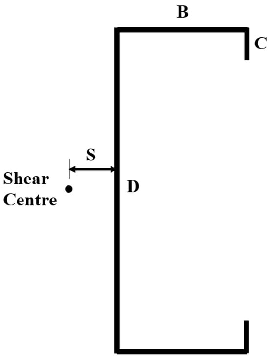
Figure 1.
Thin-walled channel section.
2.2. Twist Rotation
A simply supported channel-section beam of length L subjected to a uniformly distributed vertical load q acting on the top flange is shown in Figure 2. Because the load acts eccentrically from the shear centre, the beam is subjected to both bending and torsion. In order to calculate the longitudinal stresses due to torsion caused by this loading condition, it is necessary to obtain the solution to the classical differential equation of torsion [,]. The classical differential equation of torsion for the twist rotation ϕ about the longitudinal z axis is given by [,]
where E is the elastic modulus, G is the shear modulus, Iw is the warping constant, J is the torsion constant, the derivatives of ϕ are with respect to z, and mz is the uniformly distributed twisting moment caused by the load q expressed as
where d = B/2 + S is the horizontal distance of the load from the shear centre.
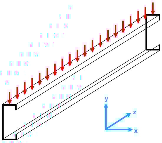
Figure 2.
Channel subjected to uniformly distributed load.
The solution of Equation (1) will be in the form of a homogeneous and a particular solution [] to be calculated so that
The homogeneous solution is given by
where C1, C2, C3 and C4 are arbitrary constants to be determined from the boundary conditions, and k is defined by
Since the distributed moment is constant, a particular solution is given by
and so the twist rotation in Equation (3) is expressed as
At each end of the beam (z = 0 and L), the section is restrained from rotating (ϕ = 0) but is free to warp (ϕ″ = 0). Using these four boundary conditions yields the following expressions for the arbitrary constants:
and so the final expression for the twist rotation becomes
and the corresponding derivatives are
The maximum twist rotation occurs at the location where the first derivative of ϕ (Equation (10)) is equal to zero. After Equation (10) is made equal to zero and solving for z, the value obtained is z = L/2, which means the maximum twist rotation occurs at mid-span. Substituting z = L/2 into Equation (9) gives the following expression for the maximum twist rotation:
2.3. Bimoment
Thin-walled beams in which the rate of change of the twist rotation varies along the member have a stress resultant known as the bimoment B, which can be calculated as follows []:
where ϕ″ is given by Equation (11). A plot of the bimoment along the member reveals that the maximum bimoment occurs at mid-span, as shown in Figure 3. Substituting Equation (11) into Equation (13) and putting z = L/2 results in the following expression for the maximum bimoment at mid-span:
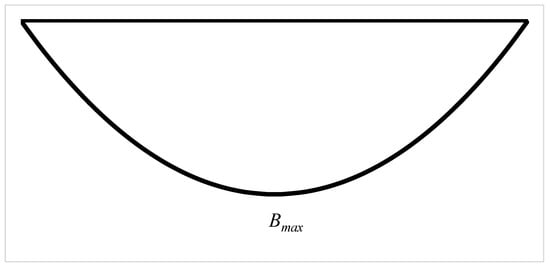
Figure 3.
Variation of bimoment along the member.
2.4. Stresses
The longitudinal stresses fb due to bimoment are given by []
where ω is the sectorial coordinate (also known as the warping function), which describes the warping pattern of the section. The longitudinal warping displacements produced by twisting are proportional to the sectorial coordinate. The sectorial coordinate is calculated as []
where h is the perpendicular distance from the shear centre to the mid-thickness line of each plate element in the section. Using Equation (16), the sectorial coordinate for a thin-walled channel section was calculated and is shown in Figure 4.
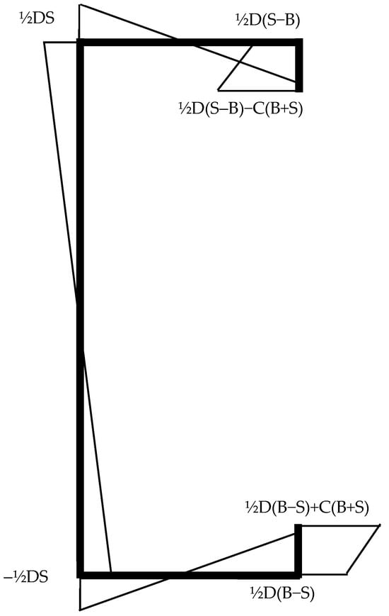
Figure 4.
Sectorial coordinate for thin-walled channel.
From Equation (15), it can be seen that the stress distribution due to the bimoment will have the same shape as the sectorial coordinate. The maximum longitudinal stress in the cross-section caused by the bimoment will occur at the location of the maximum value of the sectorial coordinate. In the case of a thin-walled lipped channel, it can be seen from Figure 4 that the maximum stress occurs at the lip edges.
3. Example
The channel section shown in Figure 5 is of length L = 5000 mm and is subjected to a uniformly distributed load q = 1.0 N/mm acting in the middle of the top flange. The channel has a web depth of 200 mm, a flange width of 80 mm, a lip length of 20 mm and a thickness of 1.5 mm. The section properties of the channel were calculated using the cross-section analysis program THIN-WALL-2 [,] as
where Zx is the section modulus for bending about the horizontal x axis. The elastic modulus is E = 200,000 MPa, Poisson’s ratio ν = 0.3, and the shear modulus G is calculated from [] as
Iw = 4.493 × 109 mm6
J = 450.0 mm4
Zx = 3.888 × 104 mm3
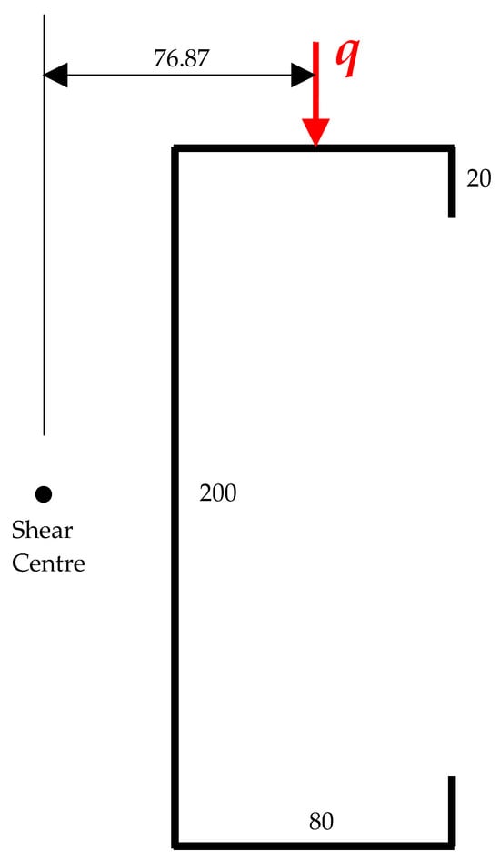
Figure 5.
Example channel section.
The horizontal distance of the load from the shear centre is 76.87 mm, and so the uniformly distributed twisting moment is calculated from Equation (2) as
mz = −76.87 Nmm/mm
From Equation (12), the maximum twist rotation at mid-span is
and from Equation (14), the maximum bimoment at mid-span is
ϕmax = 0.63406 rad = 36.33°
Bmax = −0.2183 kNm2
The sectorial coordinate calculated by THIN-WALL-2 is shown in Figure 6, where the values are the same as the expressions in Figure 4. It can be seen in Figure 6 that the maximum value of the sectorial coordinate occurs at the tip of the lips. This is also the location of the maximum longitudinal stress due to the bimoment calculated from Equation (15) as
fb = 323.1 MPa
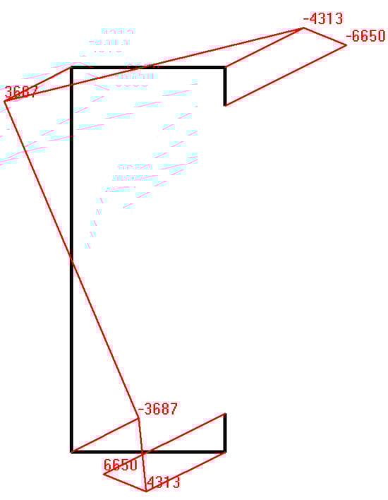
Figure 6.
Sectorial coordinate (mm2).
The longitudinal stress distribution caused by the bimoment calculated by THIN-WALL-2 is plotted in Figure 7, where positive values indicate tensile stress and negative values indicate compressive stress. It can be seen in Figure 7 that the maximum longitudinal stress calculated by THIN-WALL-2 agrees with the above value for fb calculated by Equation (15).
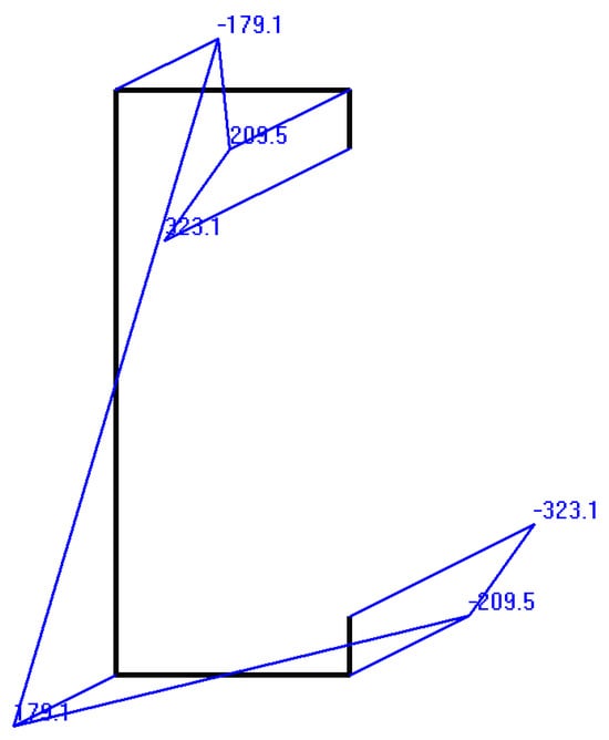
Figure 7.
Longitudinal stresses due to bimoment (MPa).
The maximum bending moment occurs at mid-span and is calculated from simple statics as
and the corresponding maximum longitudinal bending stress is
The longitudinal stress distribution caused by the bending moment calculated by THIN-WALL-2 is plotted in Figure 8. It can be seen in Figure 8 that the maximum value of the longitudinal stress occurs at the flanges and agrees with the above value for fm. More significantly, by comparing fb and fm for this example, it is found that the maximum longitudinal stress due to torsion is four times greater than that due to the bending moment.
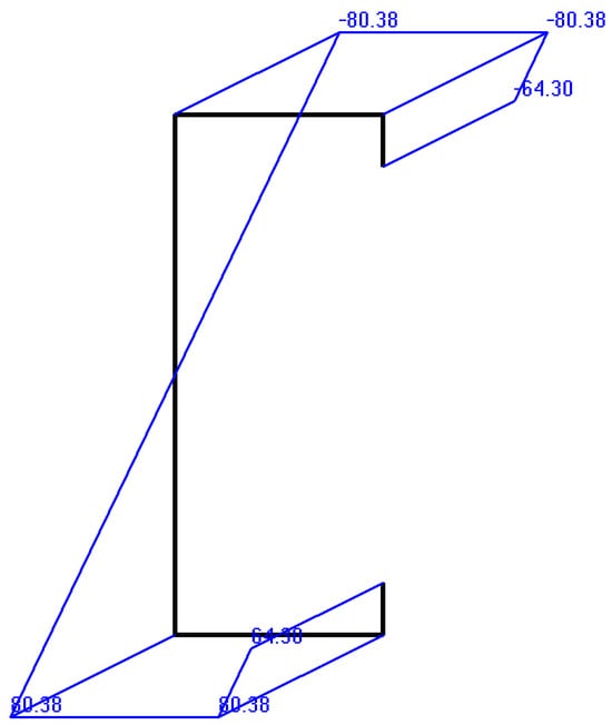
Figure 8.
Longitudinal stresses due to bending moment (MPa).
The longitudinal stress distribution caused by the combined bimoment and bending moment calculated by THIN-WALL-2 is plotted in Figure 9, where the maximum longitudinal stress is 259.5 MPa at the flange-web junctions.
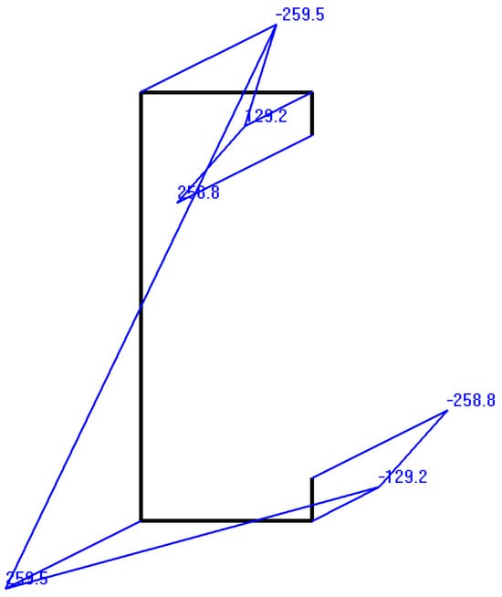
Figure 9.
Longitudinal stresses due to combined bimoment and bending moment (MPa).
4. Finite-Element Analysis
4.1. Introduction
To validate the theoretical derivation of the angle of twist rotation and the longitudinal stresses derived in the previous sections, the channel member in the previous example was analysed using the commercial finite-element analysis program Strand7 []. The channel was modelled using four-node shell elements, which were developed based on the thin-shell theory described by Jetteur and Frey []. Each node has six degrees of freedom comprising translational displacements along the x, y and z axes and rotational displacements about the x, y and z axes. A convergence study found that a mesh size of 5 × 5 mm plate elements was satisfactory to achieve an accurate solution.
4.2. Boundary Conditions
To achieve the simply supported boundary conditions at each end of the beam, every node around the cross-section was restrained from displacing along the x and y axes, as shown in Figure 10. This type of restraint prevents the ends from rotating about the longitudinal z axis but allows the section to warp. To prevent rigid-body translation of the member along the z axis, a restraint was applied to the node at the centre of the web at mid-span. In addition, rigid links were placed around the cross-section at mid-span to prevent distortion of the channel section.
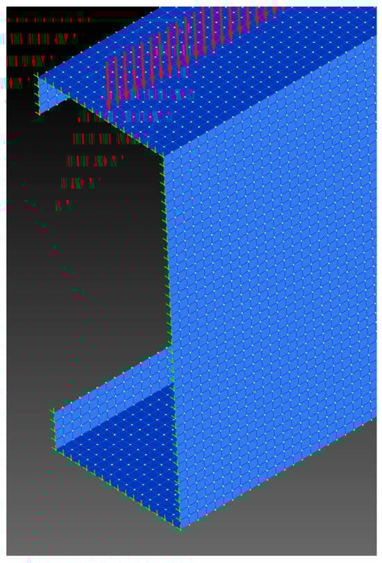
Figure 10.
Finite-element model of channel member showing boundary conditions and uniformly distributed load.
4.3. Results
A linear elastic analysis on the channel member was performed using Strand7. The maximum twist rotation at mid-span was reported to be 36.30°, which agrees very well with the theoretical value calculated from Equation (12). The maximum longitudinal stress in the section was reported as 260.5 MPa, which is in close agreement with the maximum stress shown in Figure 9. The deformed shape of the member with the longitudinal stress distribution is shown Figure 11, where the maximum stresses can be seen at the flange-web junctions.
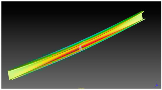
Figure 11.
Deformed shape and longitudinal stress distribution from finite-element linear analysis.
The channel was analysed with five different thicknesses, and the results are shown in Table 1. Table 1 shows that all the theoretical results are in very close agreement with the finite-element analysis.

Table 1.
Results of finite-element analysis.
Thus, the finite-element analysis validates the theoretical solution for calculating the deformations and stresses caused by bending and torsion for a thin-walled channel member subjected to a uniformly distributed load.
5. Comparison of Stresses Due to Bending and Torsion
To compare the stresses due to bending and torsion in thin-walled channels, five standard Australian 200 mm deep cold-formed steel channels subjected to a uniformly distributed load acting at the centre of the top flange were analysed using the theoretical equations derived in Section 2. The dimension symbols for the cold-formed steel channel sections are shown in Figure 12. The dimensions of the five channels are shown in Table 2, and the section properties calculated by the program THIN-WALL-2 are shown in Table 3.
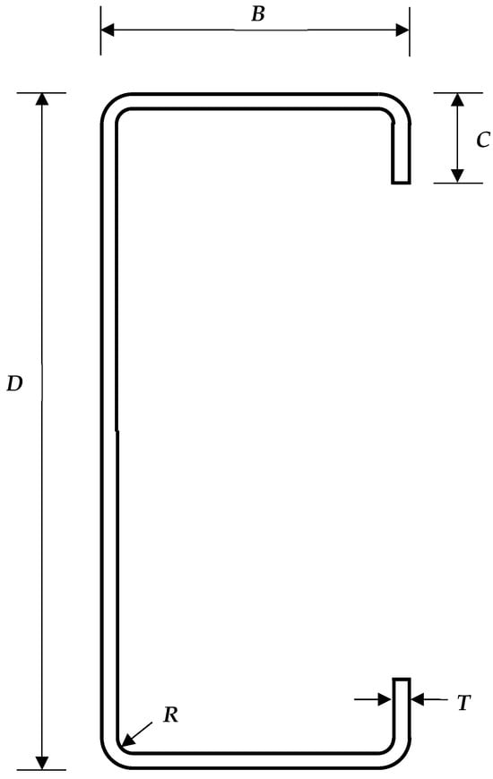
Figure 12.
Dimensions of cold-formed steel channel section.
Table 2.
Dimensions of cold-formed steel channels.
Table 3.
Section properties of cold-formed steel channels.
Figure 13 shows the variation of the ratio of the maximum stress due to the bimoment fb with the maximum stress due to the bending moment fm with the span length L for the five channels. The graph in Figure 13 shows that the fb/fm ratio is always greater than 1.0 for all practical span lengths, indicating that the maximum stress due to the bimoment is always greater than the maximum stress due to the bending moment. The ratio is particularly high for short span lengths and is also high for very thin channels. The ratio decreases as the span length increases, with the decrease being more significant for the thicker channels.
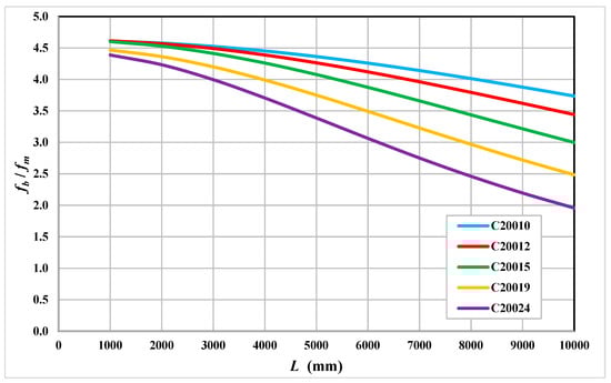
Figure 13.
Ratio of torsion stress fb to bending stress fm.
The above results can be investigated further by examining the dimensionless torsion parameter kL (Equation (5) multiplied by the span length L), which can be used to determine if the member is in a state of either warping torsion or uniform torsion or a combination of these (non-uniform torsion or mixed torsion). Kollbrunner and Basler [] showed that, for small values of kL (<2.0), the member is predominantly in a state of warping torsion, while for large values of kL (>5.0), the member is mainly in a state of uniform torsion. Values of kL between 2.0 and 5.0 indicate that the member is in a state of non-uniform (mixed) torsion. Figure 14 shows the relationship between kL and the span length for the cold-formed steel channels. It can be seen in Figure 14 that thin channels and channels with short span lengths all have low values of kL, which indicates that these channels are predominantly in a state of warping torsion and hence experience large stresses due to the bimoment.
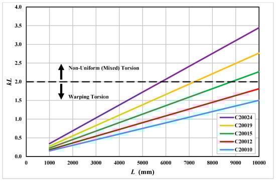
Figure 14.
Torsion parameter kL.
For beams that undergo both bending and torsion, AISI S100-16 [] and AS/NZS 4600 [] require that the design bending-moment capacity must be multiplied by a reduction factor R, calculated as follows:
where fmax is the maximum stress in the section due to the bending moment, while fm and fb are the bending and torsional stresses at the location in the section where the combined bending and torsion stress effect is greatest. Figure 15 shows the relationship between R and the span length L for the cold-formed steel channels. As expected, the reduction in the bending-moment capacity is high for short-length beams and also for very thin channels. The reduction decreases as the span length is increased, with the decrease being more significant for thicker channels.
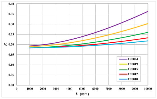
Figure 15.
Design bending-moment capacity reduction factor R.
6. Discussion
The analysis described in this paper involves the solution of the torsion differential equation to determine the twist rotation, bimoment and longitudinal stresses caused by torsion in thin-walled channels subjected to a uniformly distributed load acting on the top flange. The solution was validated by a linear elastic finite-element analysis. It should be emphasized that the theory presented in this paper is linear and does not take into account any non-linear effects due to material and geometric non-linearity, nor any buckling effects. The aim of this research was to calculate the stresses due to torsion in the linear elastic range and to compare these stresses with those due to bending. It should also be mentioned that the results in Section 5 show that the span length and channel thickness are the main parameters that affect the stresses due to torsion. Therefore, analysing different-sized channels would still lead to the same conclusions regarding span and thickness.
Future work on this subject could involve non-linear analysis, which takes into account material and geometric non-linearity, with the inclusion of geometric imperfections. A non-linear analysis may also detect possible distortions of the channel caused by the load acting in the middle of the top flange. The longitudinal stresses caused by bending and torsion may cause buckling in thin-walled members and so this would also be a research topic worthy of investigation. Performing physical tests on thin-walled channels subjected to a uniformly distributed load on the top flange would also be a useful exercise, although the practicalities of the test rig setup would require careful consideration. All the future work described above may lead to design equations for thin-walled members under torsion and combined bending and torsion.
The results of this study show that the longitudinal stresses due to torsion can far exceed those due to bending. Therefore, in the case of cold-formed steel channel purlins subjected to wind load acting on the top flange, the engineer has to minimize the magnitude of torsion in the channel. This can be achieved by connecting roof sheeting to the channel and also connecting bracing at various points along the member to prevent the channel from twisting.
7. Conclusions
Thin-walled channels such as cold-formed steel purlins are designed to resist wind loads acting on the top flange. Because this uniformly distributed load acts eccentrically from the shear centre, the channels may undergo torsion along with bending moment. It may be possible that the longitudinal stresses caused by torsion exceed those caused by bending. Therefore, the aim of this research was to calculate and compare the longitudinal stresses caused by bending and torsion in thin-walled channels under a uniformly distributed load acting on the top flange.
In this paper, the differential equation for torsion was solved for thin-walled channel members subjected to a uniformly distributed load acting in the middle of the top flange. Closed-form solutions for the twist rotation and bimoment along the member were derived. An expression for the bimoment was derived from the second derivative of the twist rotation. The bimoment was used to calculate the longitudinal stresses in the channel due to torsion.
The above theoretical derivation was validated by a finite-element linear analysis of a thin-walled channel subjected to a uniformly distributed load acting on the top flange and simply supported boundary conditions. The finite-element linear analysis showed very good agreement with the theoretical twist rotation and maximum longitudinal stress from bending and torsion.
The longitudinal stresses due to bending and torsion were compared for five standard cold-formed steel channels. It was found that the longitudinal stresses due to torsion are 3–4.5 times greater than the longitudinal stresses due to bending for most practical span lengths. In particular, thin channels and channels with short spans are most susceptible to high torsional stresses. The results further show that if torsion is present in thin-walled channel members subjected to bending moment, design engineers may be required to reduce the design bending-moment capacity by as much as 70–80%.
The theory derived in this paper and the finite-element analysis assume linear elastic behaviour, with all the stresses calculated being in the elastic range. Therefore, future work could involve geometric and material non-linear analysis, buckling analysis, and physical tests. This may lead to design equations for thin-walled members under torsion and combined bending and torsion.
In conclusion, thin-walled channels subjected to a uniformly distributed load acting eccentrically from the shear centre undergo significant longitudinal stresses due to torsion, which cannot be ignored. If these types of members are to be designed for bending moment only, the effects of torsion have to be minimised by connecting roof sheeting to the channel and using bracing that prevents the member from twisting.
Funding
This research received no external funding.
Data Availability Statement
Data supplied on request.
Conflicts of Interest
The author declares no conflict of interest.
References
- Hancock, G.J. Design of Cold-Formed Steel Structures, 5th ed.; Australian Steel Institute: Sydney, Australia, 2022. [Google Scholar]
- Put, B.M.; Pi, Y.L.; Trahair, N.S. Bending and torsion of cold-formed channel beams. J. Struct. Eng. 1999, 125, 540–546. [Google Scholar] [CrossRef]
- Gotluru, B.P.; Schafer, B.W.; Pekoz, T. Torsion in thin-walled cold-formed steel beams. Thin-Walled Struct. 2000, 37, 127–145. [Google Scholar] [CrossRef]
- Peterman, K.D.; Bian, G.; Schafer, B.W. Experimental and computational analysis of direct torsion in cold-formed steel lipped channels. In Proceedings of the Structural Stability Research Council Annual Stability Conference, Toronto, ON, Canada, 25–28 March 2014. [Google Scholar]
- Bian, G.; Peterman, K.D.; Torabian, S.; Schafer, B.W. Torsion of cold-formed steel lipped channels dominated by warping response. Thin-Walled Struct. 2016, 98, 565–577. [Google Scholar] [CrossRef]
- Schafer, B.W. Advances in the direct strength method of cold-formed steel design. Thin-Walled Struct. 2019, 140, 533–541. [Google Scholar] [CrossRef]
- Wan, H.X.; Huang, B.; Mahendran, M. Experiments and numerical modelling of cold-formed steel beams under bending and torsion. Thin-Walled Struct. 2021, 161, 107424. [Google Scholar] [CrossRef]
- AISI S100-16; North American Specification for the Design of Cold-Formed Steel Structural Members. American Iron and Steel Institute: Charlotte, NC, USA, 2016.
- AS/NZS 4600; Cold-Formed Steel Structures. Australian Steel Institute: Pymble, Australia, 2018.
- Glauz, R.S. Understanding Torsion Design for Cold-Formed Steel Members; Cold-Formed Steel Research Consortium Colloquium: Baltimore, MD, USA, 2022. [Google Scholar]
- EN1993-1-3; Design of Steel Structures, General Rules, Supplementary Rules for Cold-Formed Members and Sheeting. European Standard CEN: Brussels, Belgium, 2006.
- Xia, Y.; Glauz, R.S.; Schafer, B.W.; Seek, M.; Blum, H.B. Cold-formed steel strength predictions for torsion. In Proceedings of the SSRC Annual Stability Conference, Denver, CO, USA, 22–25 March 2022. [Google Scholar]
- Xia, Y.; Glauz, R.S.; Schafer, B.W.; Seek, M.; Blum, H.B. Cold-formed steel strength predictions for torsion and bending-torsion interaction. Thin-Walled Struct. 2024, 195, 111367. [Google Scholar] [CrossRef]
- Trahair, N.S.; Bradford, M.A. Behaviour and Design of Steel Structures to AS 4100, 3rd ed.; CRC Press: London, UK, 1998. [Google Scholar]
- Vlasov, V.Z.; Beams, T.-W.E. Thin-Walled Elastic Beams; Israel program for Scientific Translations: Jerusalem, Israel, 1961. [Google Scholar]
- Kollbrunner, C.F.; Basler, K. Torsion in Structures—An Engineering Approach; Springer: Berlin/Heidelberg, Germany, 1969. [Google Scholar]
- Davies, J.M. Torsion of Light Gauge Steel Members. In Design of Cold-Formed Steel Members; Rhodes, J., Ed.; Elsevier: London, UK, 1991. [Google Scholar]
- Papangelis, J.P.; Hancock, G.J. Computer analysis of thin-walled structural members. Comput. Struct. 1995, 56, 157–176. [Google Scholar] [CrossRef]
- Nguyen, V.V.; Hancock, G.J.; Pham, C.H. Development of the THIN-WALL-2 program for buckling analysis of thin-walled sections under generalised loading. In Proceedings of the 8th International Conference on Advances in Steel Structures, Lisbon, Portugal, 21–24 July 2015. [Google Scholar]
- Timoshenko, S.P.; Gere, J.M. Theory of Elastic Stability, 2nd ed.; McGraw-Hill: New York, NY, USA, 1961. [Google Scholar]
- Strand7 Finite Element Analysis; Strand7 Pty Ltd.: Sydney, Australia, 2024.
- Jetteur, P.; Frey, F.F. A four node Marguerre element for non-linear shell analysis. Eng. Comput. 1986, 3, 276–282. [Google Scholar] [CrossRef]
Disclaimer/Publisher’s Note: The statements, opinions and data contained in all publications are solely those of the individual author(s) and contributor(s) and not of MDPI and/or the editor(s). MDPI and/or the editor(s) disclaim responsibility for any injury to people or property resulting from any ideas, methods, instructions or products referred to in the content. |
© 2024 by the author. Licensee MDPI, Basel, Switzerland. This article is an open access article distributed under the terms and conditions of the Creative Commons Attribution (CC BY) license (https://creativecommons.org/licenses/by/4.0/).