Article

Numerical Simulation Study on Mechanical Bearing Behavior of Arch Steel–Concrete Composite Sandwich Roof

School of Architectural Engineering, Yan’an University, Yan’an 716000, China
*
Author to whom correspondence should be addressed.
Buildings 2024, 14(1), 218; https://doi.org/10.3390/buildings14010218
Submission received: 4 December 2023 / Revised: 8 January 2024 / Accepted: 10 January 2024 / Published: 13 January 2024

Abstract

:
In order to study the mechanical bearing behavior of arched sandwich roof structures, a full combination and independent action mode of concrete sandwich composite panels was constructed using the finite element method, and an arched steel–concrete composite sandwich roof with a span of 18 m was subjected to a numerical simulation test under a full-span vertical uniformly distributed load, with the bearing characteristics of the arched sandwich roof discussed in depth. The results show that the cross-sections of l/16 and l/2 of the elliptical arch sandwich roof are weak sections, and the tensile cracking of concrete appears for the first time in the upper and lower wythes of the elliptical arch sandwich roof, the von Mises stress level of the lower wythe of the l/16 section is higher under the ultimate load, and the roof shows four-part form failure characteristics. With the expansion of the cracking range of the upper and lower concrete wythes of the steel–concrete composite sandwich arch roof, the load–displacement curve of the roof structure does not decrease significantly, and the bearing capacity of the structure is high and the vertical deformation is small. The steel–concrete composite segment at the end of the roof effectively strengthens the edge constraint of the roof and improves the integrity of the sandwich roof. The upper and lower concrete wythes of the sandwich roof show a fully combined action mode in the elastic working stage and, when the concrete cracks, it shows a partial combined action mode.

1. Introduction

Concrete sandwich panels (CSPs) have the advantages of lightweight characteristics and high strength, thermal insulation, sound insulation, and noise reduction, and they are a kind of functional composite building material, which is widely used in building enclosure walls, floors, and roofs with thermal insulation requirements [1,2]. The concrete sandwich panel is mainly composed of the concrete inner and outer wythe and the middle sandwich layer of thermal insulation, and the connectors are arranged between the inner and outer concrete wythes to ensure the stable development of the bending and shear-bearing performance of the sandwich panel. The prefabricated sandwich panel structure has great advantages in the construction of industrial and civil buildings with small and medium spans.
In recent years, research on the performance of concrete sandwich panel structures has gradually become a hot topic. Joseph et al. [3] welded the steel wire mesh of the inner and outer wythes with the steel wire mesh of the connector to form a new type of lightweight sandwich panel, and the flexural bearing capacity of the unidirectional concrete sandwich panel was studied by a model test. It was verified that the composite action of steel wire mesh can effectively restrain the development of bending cracks of concrete sandwich panels. Xie et al. [4] developed a new type of sandwich panel structure based on recycled aggregate and basalt fiber-reinforced polymer shear connectors and studied the bending properties of the sandwich panel through full-scale model tests. Ding et al. [5] carried out four-point bending model tests on the ultra-high-performance concrete (UHPC) sandwich panels proposed in the study and explored the regular effects of wythe thickness, reinforcement ratio, connector spacing, and expanded polystyrene (XPS) arrangement of the sandwich panels on the bending bearing capacity. Cao et al. [6] investigated the cracking mechanism of UHPC and proposed a novel method for crack separation and its performance evaluation, and the reliability of this method was validated through experiments. Lameiras et al. [7] discussed the seismic behavior of sandwich panels formed by steel-fiber-reinforced concrete and fiber-reinforced polymer connections. Bishnoi et al. [8] conducted bending performance tests on concrete sandwich panels reinforced with plastic geogrids and polyester geogrids and investigated the differences in load-bearing capacity improvement efficiency and reliability between the two reinforcement methods. Yang et al. [9] conducted model experiments to study the bending performance of glass-fiber-reinforced concrete sandwich panels under different impact velocities. The results show the presence of four failure modes under the impact load, including face-sheet fracture, core shear fracture, side core tensile fracture, and core crushing fracture. Huang et al. [10] studied and analyzed the mechanical properties of concrete sandwich panels by establishing 2D and 3D finite element models considering material non-linearity and geometric non-linearity of concrete sandwich slabs and also discussed the bending arch deformation effect of concrete sandwich panels under the action of temperature gradient. Lou et al. [11] pointed out that the influence of the shear performance of the thermal insulation sandwich layer cannot be ignored through the shear test of the sandwich panel, but the shear-bearing capacity of the sandwich panel cannot be taken into account in consideration of safety. Chen et al. [12] studied the structural performance of concrete sandwich panels under fire and pointed out that increasing the diameter of the connectors can improve the load-bearing capacity of the sandwich panel under fire.
The connector between the concrete sandwich panel wythe is the key to ensuring the bearing performance of the sandwich panel structure. He et al. [13] studied the bearing capacity of sandwich thermal insulation wall panel connectors under axial load through pull-out and push-out tests of three kinds of glass fiber connectors. Liew Richard et al. [14] put forward a kind of steel–concrete–steel (SCS) sandwich structure of J-shaped connectors by analyzing the research progress of SCS sandwich structures in explosions, impacts, fatigue, and static loads and discussed the effectiveness of J-shaped connectors of different types of sandwich panels under different loads. Kumar et al. [15] studied the precast concrete sandwich wall panel of a new type of glass-fiber-reinforced plastic (GFRP) pipe connector and discussed the bearing capacity of the sandwich wall panel structure under the internal force of compression and bending through experimental research and theoretical analysis. Kim et al. [16], through the load test of full-scale sandwich panels, showed that GFRP grid connectors can effectively ensure the bending composite action of concrete sandwich panels.
In response to the problem of variable boundary conditions in the construction of prefabricated sandwich panel structures, Ahmad et al. [17] investigated the influence of different construction methods and end conditions on the out-of-plane bending performance of reinforced concrete sandwich panels with polystyrene cores. The experimental results indicate that the thickness and construction methods of the wythes have little influence on the failure modes of the sandwich panels but significantly affect their initial performance. In prefabricated concrete structures, ensuring reliable connections between roofs and beams/columns is crucial for safe operation. Huang et al. [18,19,20] conducted model experiments on the proposed replaceable artificial controllable plastic hinge joints to investigate the bearing and seismic performance of these connections. Additionally, they developed methods for calculating joint deformation and analyzed the underlying theories. He et al. [21] conducted shaking table tests on prefabricated concrete sandwich wall panels with dry bolt connections to investigate the seismic performance of assembled sandwich wall panel structures. The research results indicate that this type of structure exhibits excellent seismic performance.
In addition, Oliveira et al. [22] conducted a comprehensive literature review on the structural performance, thermal performance, system density, and eco-efficiency assessment of prefabricated concrete sandwich panels (PCSPs). They introduced the development and research focus of sandwich panel structures and placed a particular emphasis on evaluating the carbon dioxide equivalent (CO2eq) emissions of concrete sandwich panels. Zhao et al. [23] used the modal expansion method to study the sound insulation effect of CSPs and, combined with experimental research, pointed out that CSPs have the best sound insulation effect when the shear modulus of the sandwich layer decreases and the inner and outer wythes are of equal thickness. Based on a comprehensive study of the parameters of PCSPs, Kadhim et al. [24] developed a coupled thermal–structural finite element analysis model. They derived formulas for calculating the thermal bending and panel composite degrees of concrete sandwich panels and validated their results by comparing them with existing theoretical findings. Yu et al. [25] studied the influence of connectors on the thermal insulation performance of concrete sandwich wall panels through theoretical, experimental, and numerical simulation methods. Huang et al. [26] conducted one-side fire exposure tests to study the factors influencing the post-fire bearing capacity of PCSPs, and the results indicated that the type of connectors, type of reinforcement, and thickness of the reinforcement concrete wythe are key factors in the performance of post-fire bearing capacity of PCSPs.
In order to improve the span and bearing capacity of concrete sandwich panel structure, based on the excellent bearing performance of concrete sandwich structures and the span advantage of arch structures, a new type of prefabricated arch steel–concrete composite sandwich panel structure is proposed. In this paper, by analyzing the internal force coupling characteristics of curved concrete sandwich panel structures, the calculation model of the sandwich panel under the coupled action of axial force and bending moment is constructed. With the help of finite element software, the elliptical arched steel–concrete composite sandwich panel structure under vertical load is simulated and analyzed, and the internal force distribution and deformation law of the sandwich panel structure are discussed. At the same time, the stress distribution mode and concrete non-linear cracking behavior of a typical cross-section of a steel–concrete composite sandwich panel are analyzed in detail, and the bearing mechanism and failure mode of arched steel–concrete composite sandwich roofs are revealed. The research results of this paper can provide a reference for the span improvement and structural design of concrete sandwich structures.

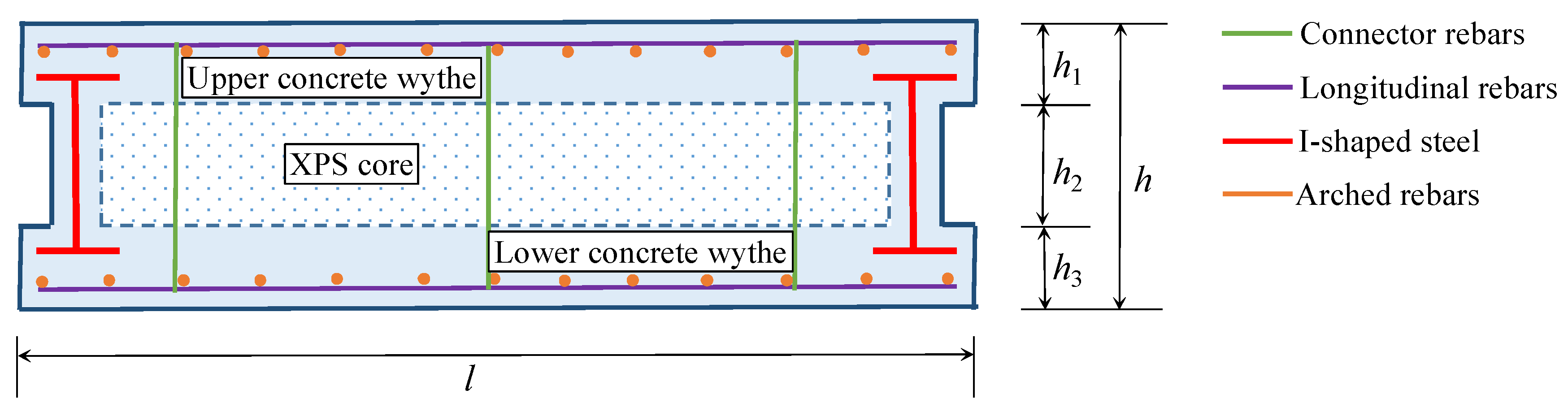
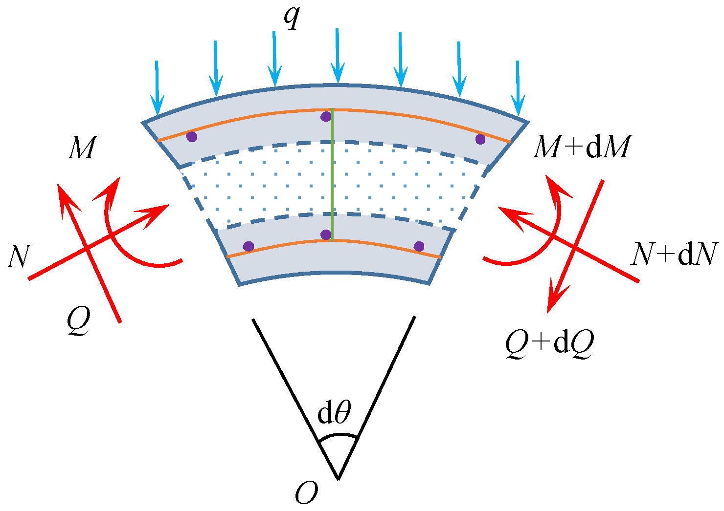
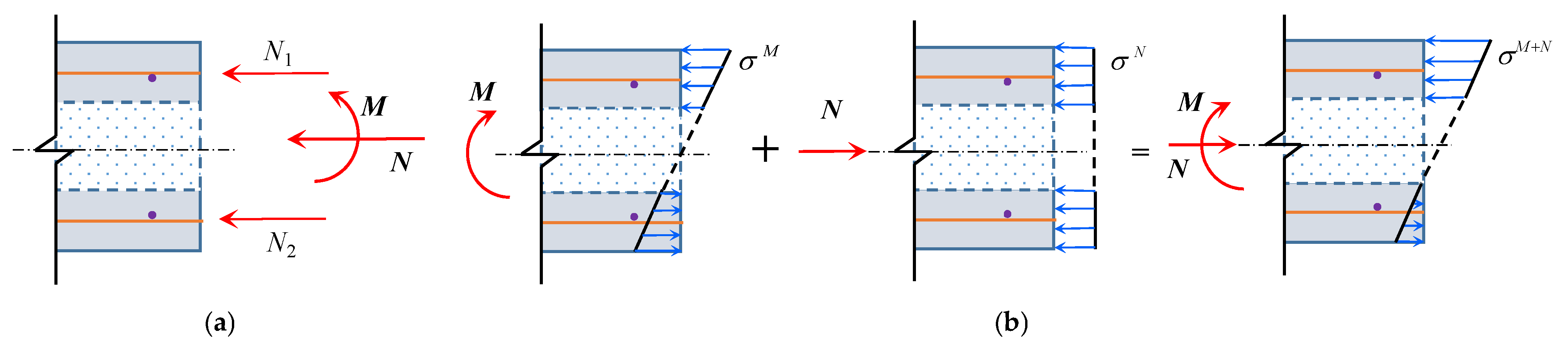
2. Calculation Model of Arch Steel–Concrete Composite Sandwich Roof

In order to improve the bearing capacity of concrete sandwich panel structures, this paper proposes to install arch steel–concrete composite beam restraint members at the end of a reinforced concrete sandwich roof to improve the bending and shear-bearing capacity of the sandwich panel and enhance the out-of-plane stability of the inner and outer wythes of the roof structure. The steel–concrete composite beam is installed at the foot of the arch roof to improve the supporting capacity of the roof and reduce the requirement of the arch foot support arrangement of the arch roof. Figure 1 shows the diagram of the cross-section of the steel–concrete sandwich roof. The steel–concrete composite sandwich roof (with length l and thickness h) is composed of upper and lower concrete wythes (with thicknesses h1 and h2, respectively), an XPS core layer (with thickness h3), steel arch beams, and connector rebars. The connector rebars coordinate the interaction between the concrete upper and lower wythes, resulting in a high bending and axial load-bearing capacity. The steel arch beams provide edge restraint for the roof, giving it high overall integrity. The XPS core layer improves the thermal insulation performance of the roof.
The related research shows that before the yield of the connectors, the inner and outer wythes of the sandwich panel show a linear and fully combined action mode [3], while for the sandwich panel structure with a weak connection between the inner and outer wythes, the action mode is fully independent. Figure 2 shows the internal force couplings of the arched concrete sandwich panel structure under transverse load.
When the action mode of the concrete sandwich panel structure is simplified, the bearing capacity of the soft sandwich insulation layer is usually ignored, and it is considered that the shear force of the section of the sandwich panel is mainly borne by the connectors. According to the characteristics of the fully combined action behavior of the inner and outer leaves of the concrete sandwich panel, Figure 3 shows the fully combined stress mode of the concrete sandwich panel under axial compression and bending internal force. The distribution of N1 and N2 in the figure is the internal force shared by the upper and lower concrete wythes under the action of bending internal force, and σM, σN, and σM+N are the stress distribution of the concrete wythe under bending moment, axial force, and compression–bending internal force, respectively.
When the concrete wythe is fully independently actioned, the upper and lower concrete wythes are individually allocated and bear the internal forces of the sandwich panel. Figure 4 presents the fully independent load distribution mode of the concrete sandwich panel under the combined action of axial force and bending moment. In the diagram, N1, M1, N2, and M2 represent the axial force and bending moment internal forces distributed to the upper and lower concrete blades, respectively. σU and σL represent the stress distributions in the upper and lower concrete wythes, respectively. In order to illustrate the stress distribution of the upper and lower concrete wythes under the combined action of axial force and bending moment, we can use the stress analysis of the upper concrete wythe as an example, as shown in Figure 5.

3. Finite Element Simulated Load Test

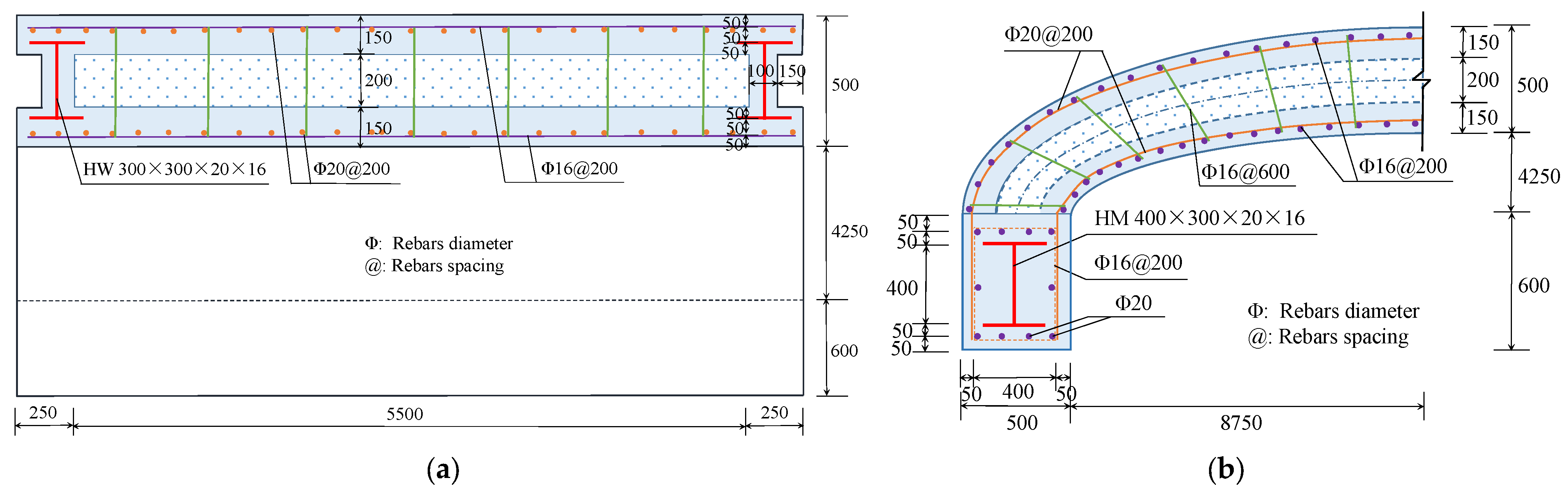
3.1. Specimen Model Design

To emphasize the spatial shape of the steel–concrete composite sandwich panel structure and demonstrate the structural behavior, the finite element model focuses on an elliptical arch roof with a span of 18 m. The roof has a height of 4.5 m and a rise–span ratio of 0.25. The arch roof structure is constructed by assembly construction mode, and the segment length of the roof is 6 m. The thickness of the concrete sandwich panel is 500 mm, and steel mesh is placed in both the upper and lower concrete wythes. Connector rebars are additionally incorporated between the wythes to enhance their combined strength. In addition, steel–concrete edge restrained arch beams are arranged at the ends of the concrete sandwich panel arch roof segment, and longitudinally arched steel–concrete supporting beams are arranged at the arch foot of the arch roof. The steel arch beam is extended into the supporting beam to form a stiffening joint area, which ensure the reliable connection between the steel arch beam and the supporting steel beam. Figure 6 shows the dimensional details of the elevation and sectional construction of the elliptical arch steel–concrete composite sandwich roof. The reinforcing bars used in the model specimens are all of HRB335 grade, while the I-beams are made of Q235 grade steel.

3.2. Load Conditions

The typical load distribution pattern for the arch roof structure is vertical uniformly distributed load, and this load arrangement pattern is also the primary basis for the design and calculation of the roof structure. When conducting non-linear load-bearing capacity analysis for the sandwich roof structure, this load pattern is used, with an increment of 0.5 kN/m2 for roof load intensity.

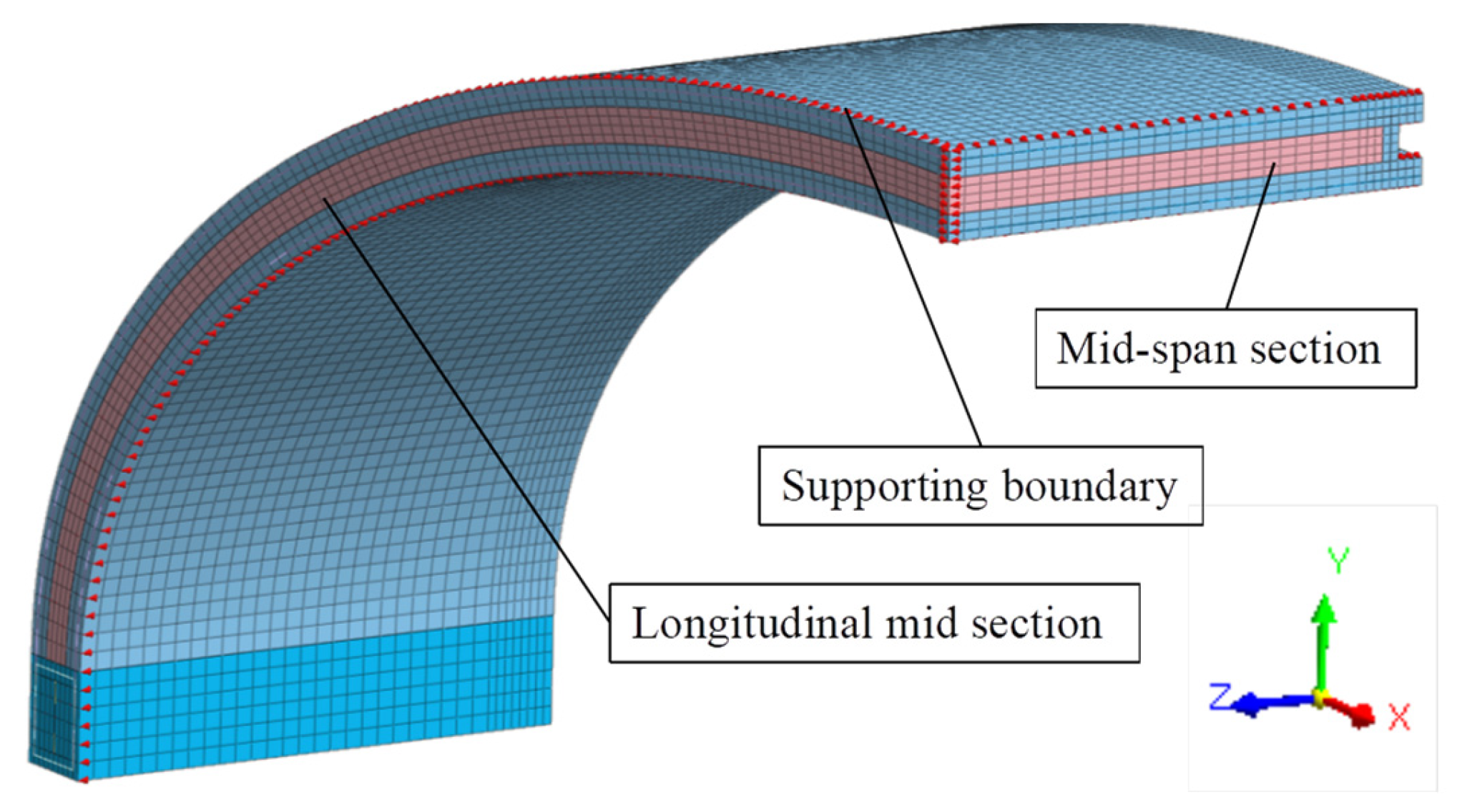
3.3. Finite Element Model
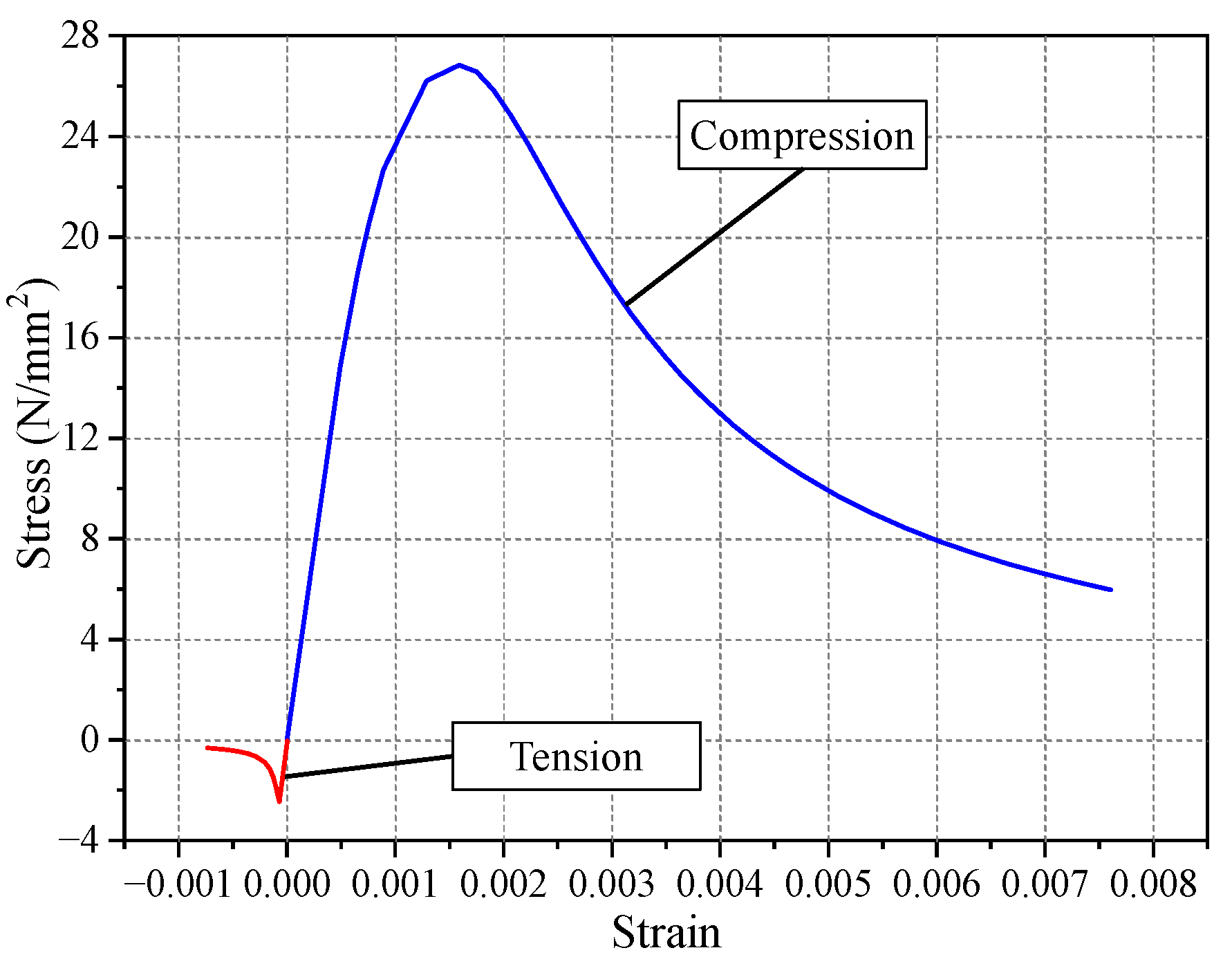
3.3.1. Materials

The upper and lower wythes, as well as the supporting beams, of the arched steel–concrete composite sandwich roof structure are made of concrete with a strength grade of C40. The elastic modulus (Ec) is 3.25 × 10⁴ N/mm2, the standard compressive strength value (fck) is 26.8 N/mm2, the standard tensile strength value (ftk) is 2.39 N/mm2, and the Poisson’s ratio (v) is 0.2. Taking into account the cracking and crushing of concrete, the shear transfer coefficients are taken as 0.95 and 0.5 for concrete crack closure and opening, respectively. The unit weight (Gc) is 2.4 × 10⁻⁵ N/mm3. The cracking behavior and non-linear mechanical behavior of the concrete material are simulated using the crack dispersion model. The stress–strain relationship for the uniaxial tensile and compressive stress of the concrete should satisfy Equation (1), and the stress–strain curve of the concrete is given in Figure 7.
σ c = ε c f tk ε tk · 1 α t ε c ε tk 1 1.7 + ε c ε tk for ε c ε tk ε c f tk ε tk · 1.2 0.2 ε c ε tk 5 for ε tk < ε c 0 ε c f ck ε ck · E c ε ck E c ε ck     f ck f ck E c ε ck     f ck + ε c ε ck E c ε ck E c ε ck     f ck for 0 < ε c ε ck ε c f ck ε ck · 1 α c ε c ε ck 1 2 + ε c ε ck for ε ck < ε c
According to the stress–strain relationship of C40 concrete in reference [27], where the parameter of the falling section of concrete under uniaxial tension (αt) is 1.81, the standard value of peak tensile strain of concrete (εtk) is 1.05 × 10⁻⁴; where the parameter of the falling section of concrete under uniaxial compression (αc) is 1.18, the standard value of peak compression strain of concrete (εck) is 1.6 × 10⁻³.
In the sandwich panel structure, the HRB335 grade steel reinforcement and Q235 grade composite I-shaped steel possess an elastic modulus (Es) of 2.0 × 10⁵ N/mm2. The standard yield strength values (fyk) for HRB335 grade steel reinforcement and Q235 grade steel amount to 300 N/mm2 and 235 N/mm2, respectively. The Poisson’s ratio (v) is 0.3. The steel is modeled as an elastic–perfectly plastic material both under tension and compression. Its stress–strain relation is given as:
σ s = E s ε s for ε s ε y ± E s ε y for ε y ε s
The insulation layer of the sandwich panel adopts XPS polystyrene board, with a modulus of elasticity (Ej) of 5 N/mm2 and a unit weight (Gj) of 3 × 10⁻⁷ N/mm3. The stress–strain relationship of the polystyrene board material follows the linear elastic behavior.

3.3.2. Elements

The concrete entities in the steel–concrete sandwich panel structure are simulated using 3D solid elements with a dimension of 50~100 mm per element. The composite I-beam steel is simulated using 2D shell elements, with the element thickness determined based on the dimension of the steel slab. The shell element dimensions are coordinated with the concrete element dimensions to ensure node coincidence and coupling of degrees of freedom. The simulation assumes no bonding or slip between the steel slab and the concrete. The reinforcement is simulated using 1D embedded truss elements, with the program automatically considering the interaction between the reinforcement and the concrete.

3.3.3. Boundary

According to the structural design of the arched steel–concrete sandwich roof model, two fixed-hinge supports are positioned on each side of the roof segment beam to create a two-hinged arch calculation model for the roof.
In order to improve computational efficiency and reduce calculation errors, a quarter model of the arched sandwich roof was established for simulation analysis. The boundary constraints at the cross-section at the mid-span of the roof and the longitudinal mid-section need to be set according to the loading conditions of the finite element model. According to the load arrangement in Section 3.2, for the working condition of uniformly distributed symmetric load over the entire span, constraints are implemented at the mid-span section of the roof to limit horizontal displacement and rotation of the section. Figure 8 shows the finite element model of the arched steel–concrete sandwich roof.

4. Results Analysis

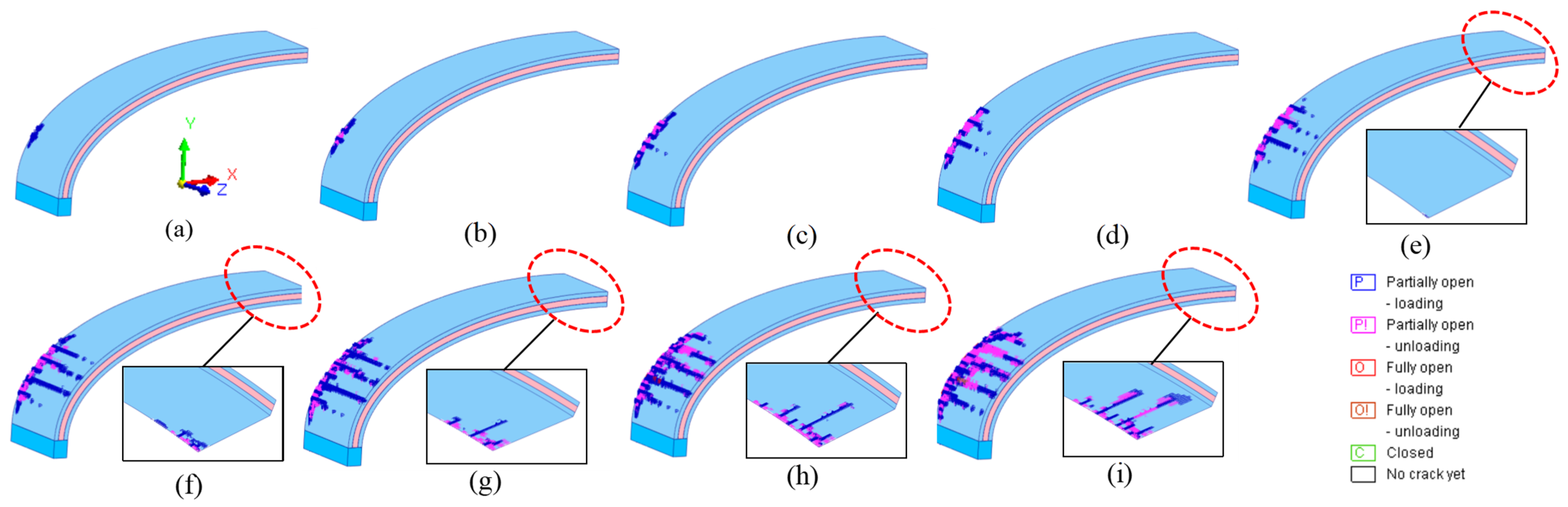
4.1. Concrete Cracking

Under vertical loading, the arch-shaped steel–concrete composite sandwich roof structure experiences significant bending moments and axial forces at different cross-sections. The concrete sandwich panels undergo various modes of failure, such as concrete cracking and crushing, under the compression–bending internal forces. Figure 9 presents the cracking situation of the concrete in the steel–concrete composite sandwich roof structure under different load levels.
Based on the analysis of the cracking of the roof concrete in Figure 9, it can be observed that the steel–concrete composite sandwich roof structure first exhibits cracking under a uniform load of 7.5 kN/m2. The cracking occurs at a location approximately x = 1.15 m (l/16) from the left support, specifically at the end of the steel–concrete composite section. As the roof load increases, the cracks in the upper wythe of the roof expand and the range widens. The results indicate that the cracking load (qcr) of the arch-shaped steel–concrete composite sandwich roof is 7.5 kN/m2, and the cracking occurs near the support in the steel–concrete composite section. This indicates that the increased steel–concrete composite form at the end of the arch-shaped roof enhances the local bending stiffness, resulting in higher distributed bending internal forces, and thus leading to the initiation of cracking at the section. Additionally, the elongated axis of the roof’s elliptical profile results in a higher negative bending moment at the l/16 section near the support, increasing the risk of tensile cracking in the concrete of the upper wythe of the sandwich roof.
When the roof load increases to q = 11 kN/m2, tension cracking and failure occur in the lower concrete wythe at the mid-span section of the arch-shaped roof. Similar to the previous case, the cracking occurs in the steel–concrete composite end of the roof. The roof exhibits a mode of failure characterized by positive bending moment at the mid-span section. As the roof load increases, the cracking area of the lower plate concrete continues to widen. Due to the presence of two distinct areas in the roof span where the concrete cracking occurs with opposite internal force characteristics, the increase in the roof load level leads to a rapid expansion of cracks in both the positive and negative bending moment cracking regions. This significantly reduces the flexural stiffness of the roof.
When the roof load continues to increase to 15.0 kN/m2, the analysis calculation is terminated due to the inability of the force and displacement of the finite element model of the roof to converge. This indicates that the sandwich panel roof structure has reached its ultimate bearing capacity state, with the ultimate load being qu = 15.0 kN/m2. Based on the cracking pattern and condition of the concrete wythe in the roof, the roof structure exhibits internal force inflection points between l/16 and l/2. The development of cracks in the arch-shaped concrete sandwich roof follows a typical four-part form compression–bending failure mode.

4.2. Deformation

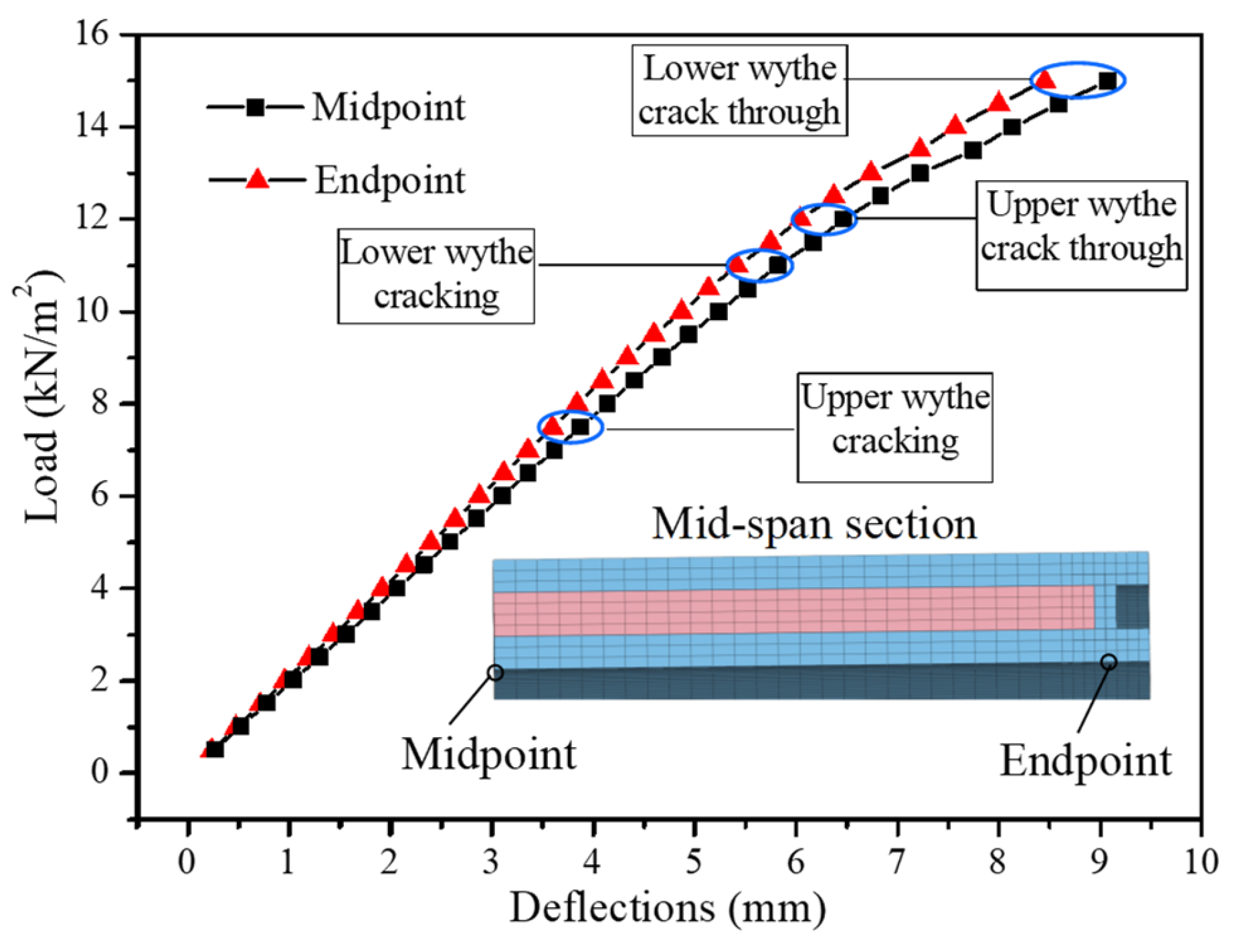
4.2.1. Vertical Deflection of Mid-Span Section

The ends of the arch-shaped sandwich roof are equipped with steel–concrete composite sections, which increase the local axial stiffness and bending stiffness of the roof, leading to varying bending characteristics along the longitudinal direction of the roof under the influence of force and moment internal forces. Figure 10 displays the vertical deflection curves of the roof endpoint and midpoint at the mid-span section of the sandwich roof under the load.
Based on the analysis of Figure 10, it can be observed that the load–deflection curves of the characteristic points of the roof exhibit a certain stiffness variation trend before and after q = 11 kN/m2. However, there is no distinct yield point or significant decrease in load-bearing capacity. This indicates that the steel–concrete composite sandwich roof has a high overall load-bearing capacity and minimal vertical deflection. Under the ultimate load qu = 15.0 kN/m2, the maximum vertical deflection at the midpoint of the mid-span section of the roof is yu = 9.07 mm, and the value is approximately l/2000 and is significantly smaller than the requirement of l/400 for vertical deflection of the roof specified in [27]. By comparing the vertical deflection at the endpoint and midpoint of the mid-span section of the roof, it can be observed that the vertical deflection at the midpoint is approximately 7% larger than that at the endpoint under the same level of load. This is primarily due to the steel–concrete composite sections at the ends of the sandwich roof, which enhance the local axial and bending stiffness of the structure, reducing the vertical deflection of the roof under load.

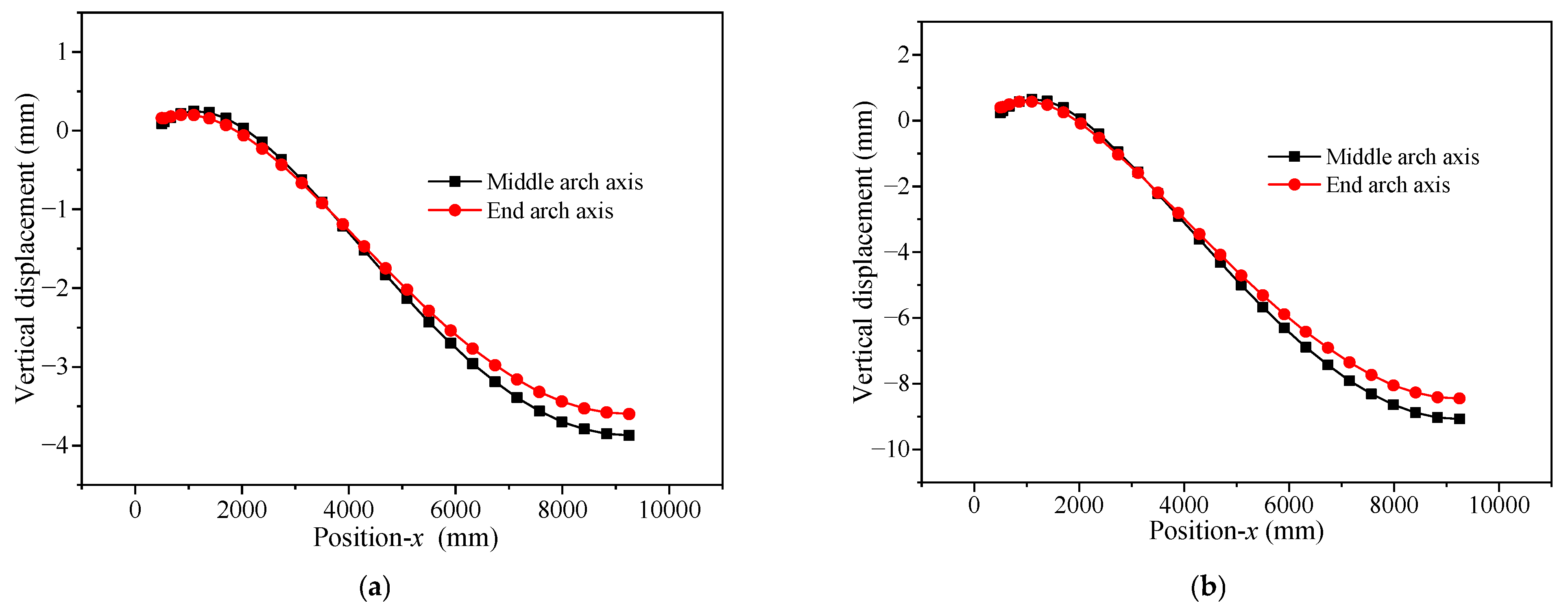
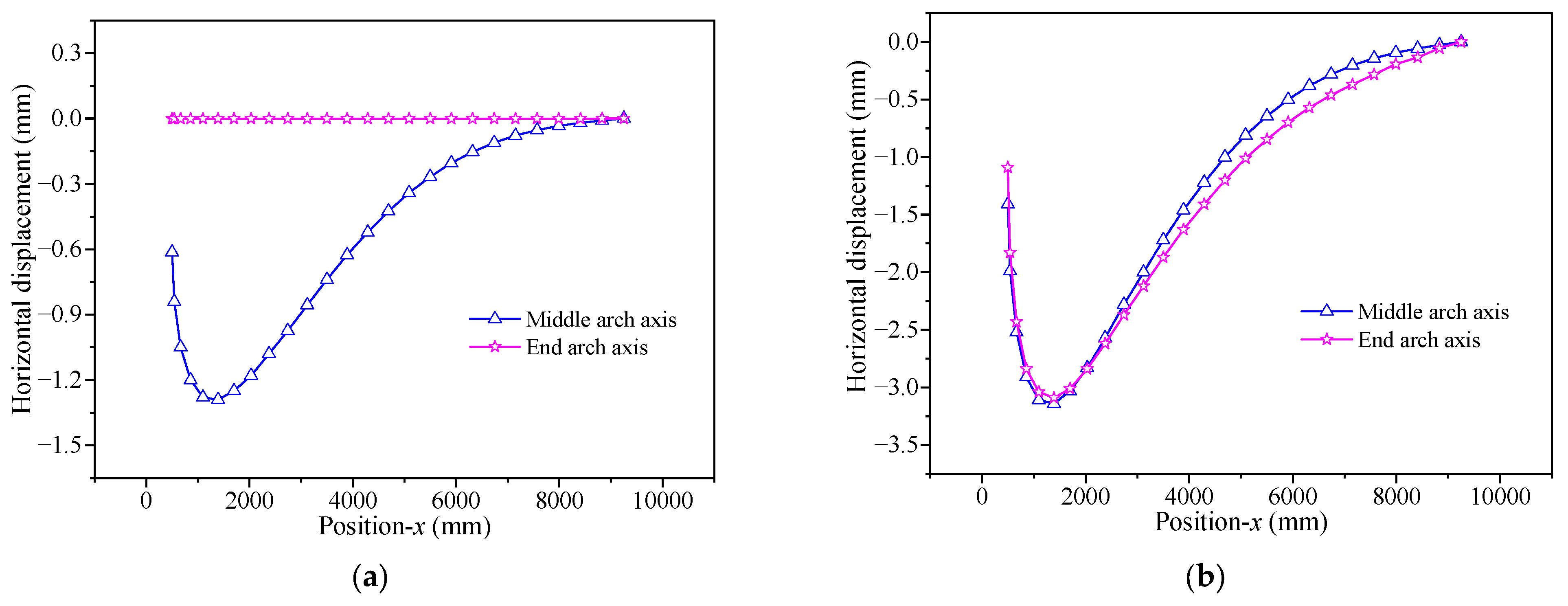
4.2.2. Arch Axis Deformation

The elliptical arch roof undergoes vertical and horizontal deformations along the arch axis under the influence of internal forces produced by the uniformly distributed vertical load. Figure 11 and Figure 12 provide the vertical and horizontal deformations of the arch axis of the elliptical arch roof under cracking loads and ultimate loads, respectively.
By analyzing Figure 11, it can be seen that the vertical deformation patterns of the arch axis at the end and middle of the roof are generally consistent under cracking loads and ultimate loads. As the load increases, the vertical deformation of the arch axis also increases. The vertical deformation of the arch axis at the middle of the roof is greater than that at the end, which is consistent with the conclusion in Section 4.2.1 that the vertical displacement at the midpoint is greater than at the endpoint. Moreover, the rapid increase in vertical deflection at the mid-span section of the roof leads to tensile cracks in the lower concrete wythe of the arched sandwich panel. Additionally, the length and extent of cracks in the concrete at that position increase with the growth of the load.
The analysis of Figure 12 shows that the horizontal deformation of the arch axis at the end of the roof under the cracking load is very small and basically increases linearly from the arch foot support to the mid-span section, while for the middle arch axis of the roof, there is a significant negative horizontal displacement at the distance of 1.15 m from the arch foot, which is due to the expansion of the elliptical arch axis under vertical load. The horizontal displacement causes the sandwich arch slab to crack in the concrete of the upper wythe under tension. As the load increases to the ultimate load qu = 15.0 kN/m2, both the end and middle sections of the roof exhibit peak horizontal displacement at a distance of l/16 from the foot of the arch. This indicates that as the load increases, the cracking and damage in the roof concrete continue to develop. The redistribution of internal forces in the roof structure exacerbates the failure mode of the negative bending moment at the l/16 section.

4.3. Stress

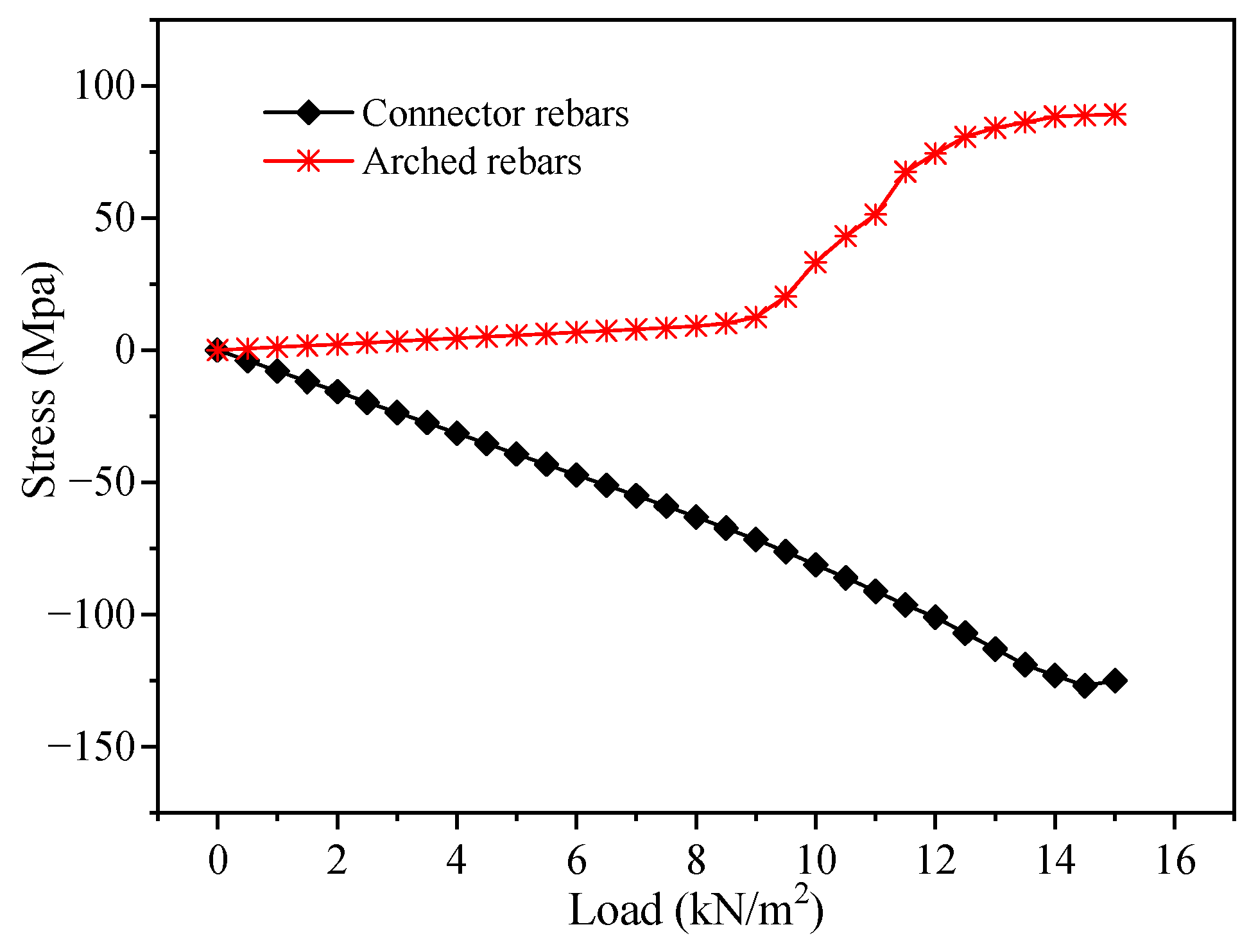
4.3.1. Steel Bar Stress

The upper and lower concrete wythes of the arch-shaped steel–concrete sandwich roof are arrangements with both load-bearing and structural steel bars. After the concrete cracking occurs in the roof, the steel bar plays a key role in enhancing the load-bearing capacity of the roof. Figure 13 illustrates the distribution of axial stress in the steel bar skeleton of the arch-shaped sandwich roof under cracking and ultimate loads.
The analysis of Figure 13 reveals that under the action of cracking loads, the overall stress level of the steel reinforcement in the arch-shaped roof is relatively low. Only a few connectors in the vicinity of the x = 1.15 m section near the foot of the arch experience higher compressive stress. When the roof load increases to the ultimate load, the stress level of the steel reinforcement in the upper and lower concrete wythes of the arch-shaped steel–concrete sandwich roof remains relatively low. However, there is a significant localized increase in stress near the l/16 section from the foot of the arch. At the upper wythe in the roof’s end section, the reinforcing bars experience peak tension stress, with σmax = 89.24 MPa. Conversely, the tension bars at this section exhibit peak compressive stress, with σmin = −125.03 MPa. Figure 14 presents the stress variations of the steel reinforcement elements with the increase in load.
From Figure 14, it can be observed that when the roof load is less than 9 kN/m2, the tension stress in the upper wythe shows a slow linear increase. Due to concrete cracking in the upper wythe at the l/16 section and the lower wythe at the l/2 section of the sandwich roof, the tension stress of the steel reinforcement increases rapidly when the roof load falls between 9 kN/m2 and 13 kN/m2. However, when the roof load exceeds 13 kN/m2, the rate of tension stress increases in the upper wythe slows down. Additionally, the stress variation curve of the tension bars in Figure 14 exhibits a clear unidirectional linear growth trend, indicating the significant role of the connectors in load transfer between the upper and lower wythes.

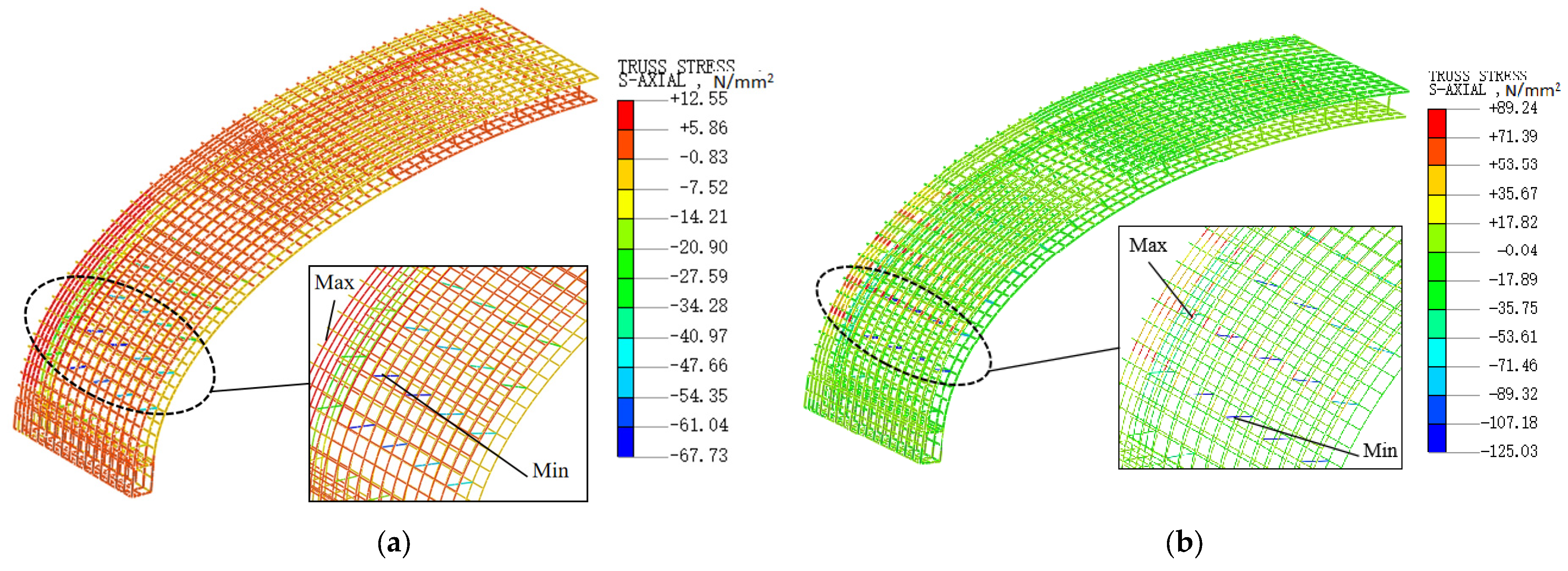
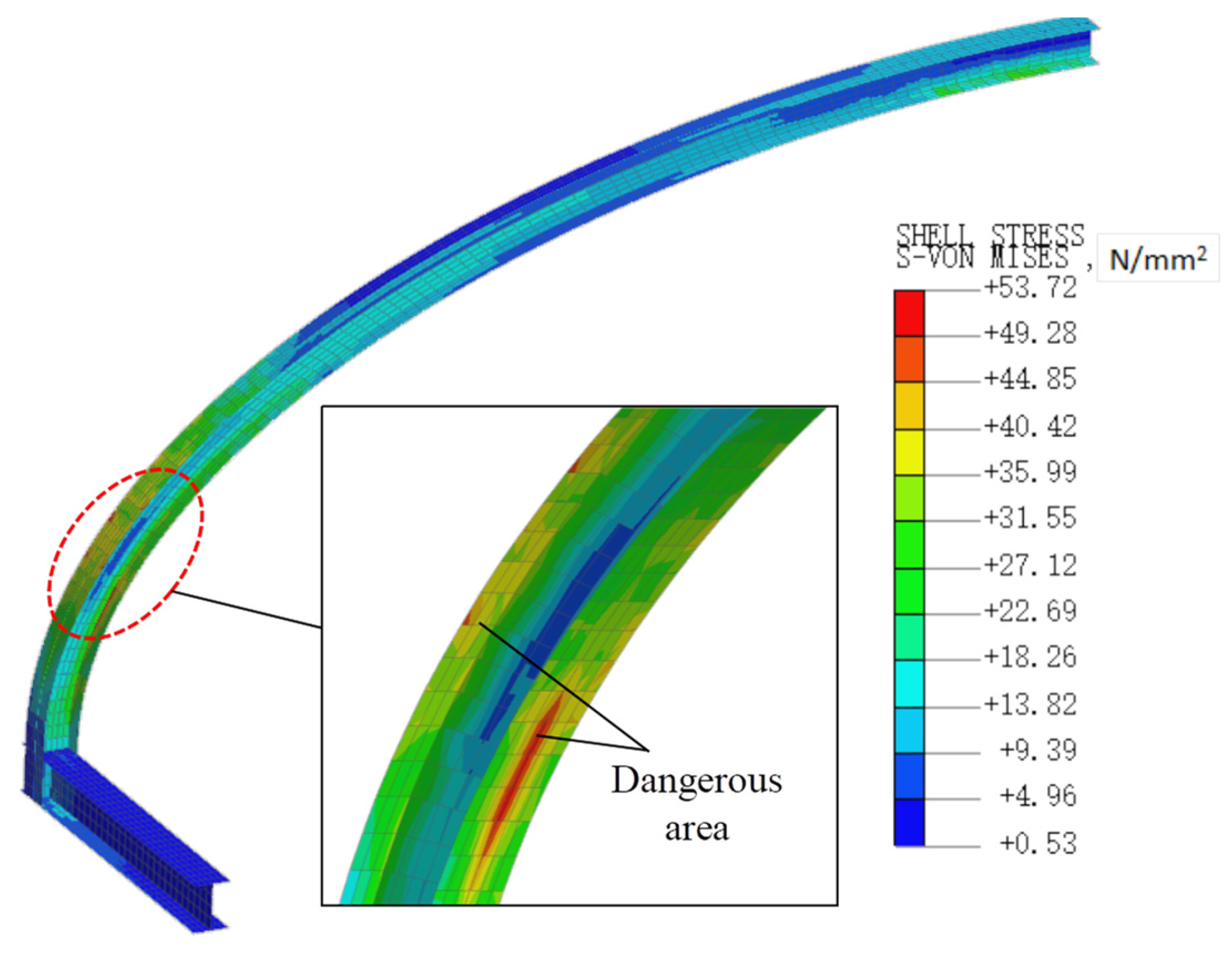
4.3.2. Steel Plate Stress

By introducing a steel–concrete composite section at the end of the arch-shaped roof, the axial and flexural stiffnesses of the roof are improved, effectively enhancing the vertical load-bearing performance of the arch-shaped roof. According to the analysis of concrete cracking in the arch-shaped roof, it can be observed that the end of the steel–concrete composite sandwich roof is the first region to crack, and the embedded I-section steel plate in this area plays a crucial role in the structural load-bearing performance stability. Figure 15 presents the distribution of von Mises stress in the I-section steel skeleton of the sandwich roof under the ultimate load of 15 kN/m2.
From Figure 15, it can be observed that the von Mises stress of the embedded I-section steel plate at the end of the roof is relatively high at the l/16 section. The peak stress (σs = 53.72 MPa) occurs at the upper and lower flange plates, indicating that the peak stress region in the upper and lower flanges at the l/16 section is the critical area for strength failure. Additionally, the overall equivalent stress of the I-section steel beam installed in the supporting beam is relatively low, allowing for flexibility in selection based on engineering design requirements.

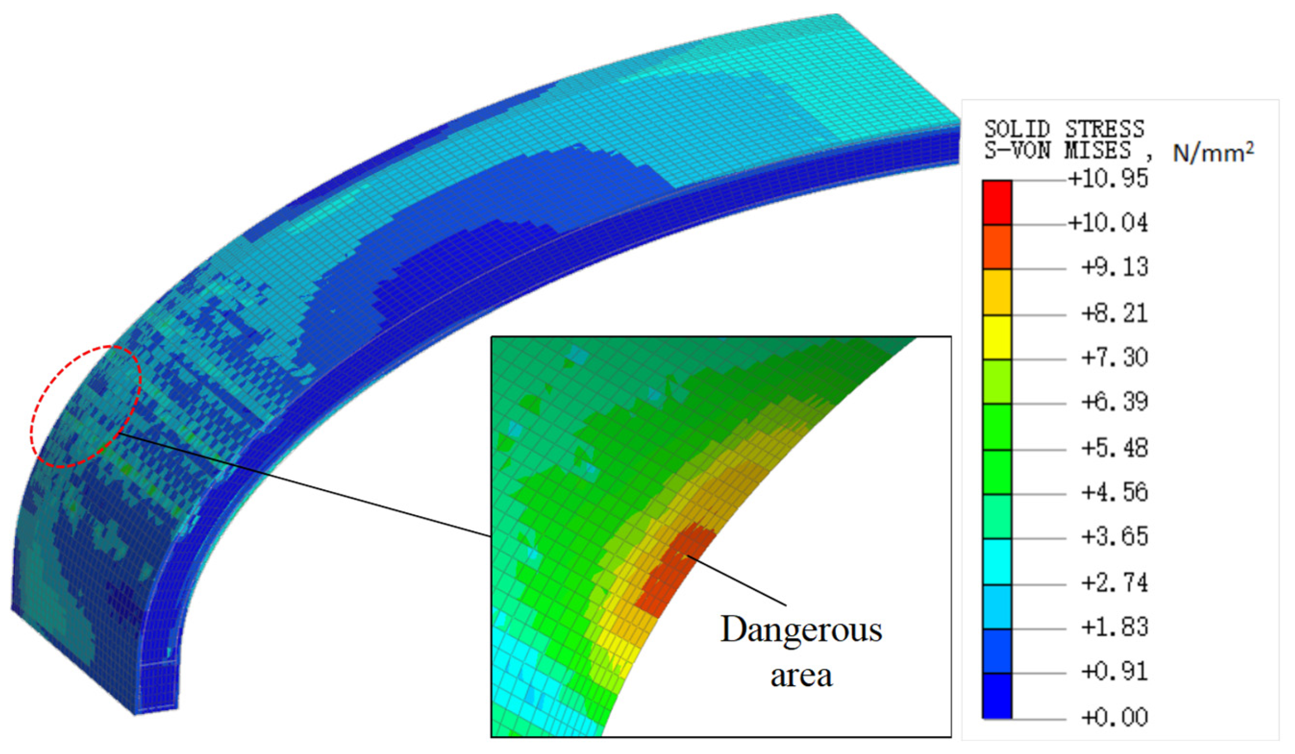
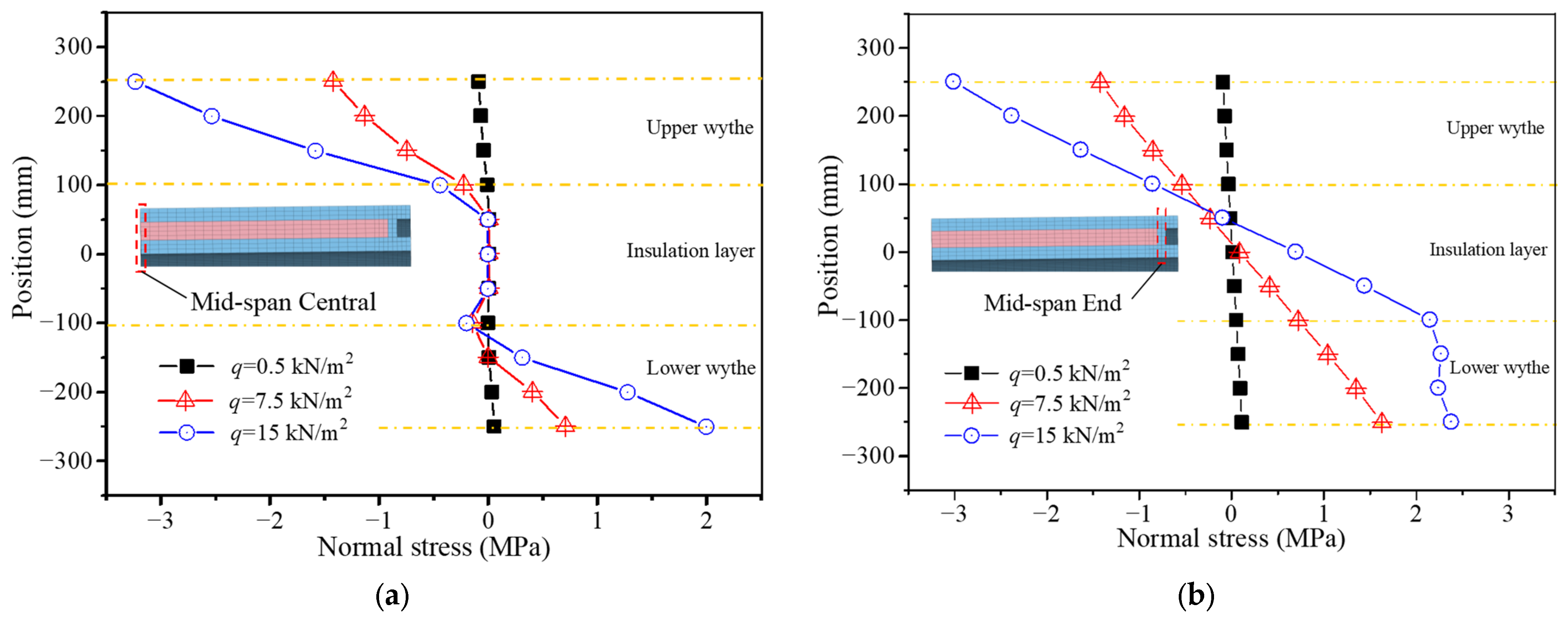
4.3.3. Concrete Stress
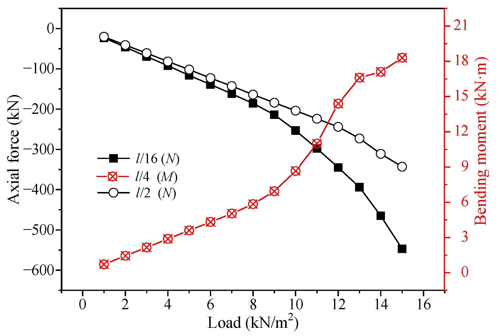
Due to the characteristic that the compressive strength of concrete material is significantly higher than its tensile strength, the concrete wythe in the steel–concrete composite sandwich roof structure experiences tensile cracking first under roof load. Figure 16 shows the distribution of von Mises stress in the concrete of the sandwich roof under the ultimate load of 15 kN/m2. Figure 16 demonstrates that the overall von Mises stress in the concrete wythe of the sandwich roof is relatively low under the ultimate load (15 kN/m2). However, at the l/16 section of the roof, there is a concentrated region of von Mises stress peaks in the lower wythe. This phenomenon is primarily caused by the combination of a larger negative bending moment and axial compression force at the l/16 section, resulting in non-uniform compressive stress. Based on the analysis of concrete cracking in the sandwich roof, it is evident that there is a tendency for the concrete in the lower wythe to be crushed in the l/16 section, indicating a potential failure trend.

4.4. Internal Force

The arch-shaped steel–concrete composite sandwich roof structure mainly experiences axial forces and bending moments under vertical loads. Table 1 presents the axial forces and bending moments for typical sections of the elliptical arch roof structure (x = 0 m, l/16, l/4, l/2) under the elastic load of 0.5 kN/m2, the cracking load of 7.5 kN/m2, and the ultimate load of 15 kN/m2. According to the principle of simplified eccentricity based on the axial force eccentricity formula e = M/N, the eccentricity index for the typical sections is calculated.
Analyzing Table 1 reveals that under different load levels, the axial forces for the typical sections of the arch-shaped roof are all compressive, and the compressive forces can improve the bending capacity of the concrete sandwich panels to some extent and reduce the risk of tensile cracking caused by bending moments. Comparing the bending moments for different cross-sections of the roof, it is observed that the moments near the support location are negative, while the moments near the mid-span are positive. Within the range of l/16 to l/4, there is a shift in the nature of bending moments, indicating that this range serves as a transition zone for the change in failure mode for the arch-shaped steel–concrete composite sandwich roof. This is in agreement with the conclusion of the analysis of concrete cracking in Section 4.1.
In addition, the internal forces for the different typical cross-sections generally exhibit a linear increase with the increase in load levels. However, the axial forces for the l/16 section, bending moments for the l/4 section, and axial forces for the l/2 section show different patterns. Figure 17 illustrates the variations of the axial forces for the l/16 and l/2 sections and bending moments for the l/4 section under different load levels. Analyzing Figure 17 reveals that when the load level is below the cracking load, the internal forces for all sections show a linear increase. However, when the load level reaches the ultimate load, the axial force for the l/16 and l/2 sections increases by 57.7% and 11.8% compared to the linear increase, and the bending moment for the l/4 section increases by 69.4% compared to the linear increase. This analysis indicates that as the cracking damage in the concrete panels of the arch-shaped roof develops, there is a redistribution of internal forces in the critical sections of the roof components.
Upon comparing the simplified eccentricities of the different typical sections under the various load levels in Table 1, it is evident that apart from the support section (x = 0 m), the eccentricities of the other sections change due to the redistribution of internal forces. When the roof load is less than the cracking load, the eccentricities of the typical sections remain relatively unchanged. However, as the roof load increases from the cracking load to the ultimate load, the simplified eccentricity for the l/16, l/4, and l/2 sections decreases by 44.4%, increases by 50%, and decreases by 8.0%, respectively. Considering the analysis of the variation in internal forces for the typical sections, it can be concluded that the occurrence of tensile cracking in the concrete sandwich roof leads to a redistribution of internal forces in the components, thereby increasing the complexity of analyzing the internal forces of steel–concrete composite sandwich roof structures.

5. Discussion

This study employs a crack diffusion model to simulate the non-linear mechanical properties of concrete materials. The suitability of this concrete crack model for simulating sandwich panels has been successfully verified in reference [10]. By comparing the established 2D and 3D finite element models with the theoretical analysis of concrete sandwich panels in [28] and the experimental results of full-scale concrete sandwich panel physical models in [29], it has been confirmed that the crack diffusion model is reliable for calculating concrete sandwich panel structures.
In view of the convergence error requirements of the finite element model calculations, the calculation of the load-bearing capacity of the arch-shaped concrete sandwich roof in this study did not involve concrete crushing and steel reinforcement yielding. Therefore, the load–displacement curve only reflects the cracking through the upper and lower concrete wythes in Section 4.1. It is pointed out in Section 4.1 that the cracking through the upper concrete wythe at the l/16 section of the roof and the cracking of the lower concrete wythe at the l/2 section have a good correspondence with the characteristic points of the load–displacement curve in Section 4.2. Similar research conclusions have been reported in Hamed [30].
Due to the close relationship between the load-bearing mode of concrete sandwich panels and the structural response, as the load level increases, the cracked damage zone of the sandwich roof structure expands continuously, and the stress distribution pattern of the concrete sandwich panels also changes. Figure 18 presents the distribution of normal stresses at the key points of the mid-span section in the steel–concrete composite sandwich roof structure under elastic load (q = 0.5 kN/m2), cracking load (qcr = 7.5 kN/m2), and ultimate load (qu = 15 kN/m2) conditions. A detailed analysis of Figure 18a reveals that the distribution of normal stresses along the height of the mid-span section is closely related to the magnitude of the roof load. The normal stresses are linearly distributed under the elastic load, indicating a fully composite action state in the sandwich panel. However, as the load increases to the cracking load and ultimate load, the stress distribution along the cross-section becomes irregular. Both the upper and lower wythes experience a compression–bending stress state. However, it is observed that the simplified axial force in the upper wythe has shifted to the sandwich core region, resulting in a non-uniform compressive stress distribution across the entire cross-section. In contrast, the simplified axial force in the lower wythe remains in the lower wythe region, causing a combination of small compressive stresses and significant tensile stresses in the lower wythe. Hence, the sandwich panel exhibits a partially composite action state. An analysis of Figure 18b reveals that the normal stresses at the ends of the mid-span section exhibit a linear distribution under the elastic load and the cracking load. However, as the roof load increases to the ultimate load, the tensile stress in the concrete of the lower wythe reaches a limit of 2.39 MPa, causing it to crack and cease to carry the load. As a result, the neutral axis of the cross-section moves upwards owing to the bending effect.
Based on the analysis above, it can be concluded that the stress distribution pattern of the arch-shaped roof sandwich panels has both similarities and differences compared to the computational model of the arch-shaped concrete sandwich structure discussed in Section 2 of this paper. The full composite action and independent composite action are two ideal load-carrying modes for concrete sandwich panels. However, the actual stress distribution of concrete sandwich panels often falls within a partially composite action mode, which is between the two ideal modes. This conclusion has been clearly verified in several references [3,10,16,28].
It should be noted that this paper focuses on the study of elliptical arch-shaped steel–concrete composite sandwich roofs, which have unique characteristics in terms of shape, size, and construction. These specific features limit the generalization of the research findings. Factors such as arch axis shape, type and quantity of connectors, and layout of supports can significantly influence the load-bearing performance of this type of structure. The investigation of these critical parameters will be conducted in future research.

6. Conclusions

This study investigates the regular deformation and cracking characteristics of arch-shaped steel–concrete composite sandwich roofs under full-span uniformly distributed load through numerical simulation analysis. Additionally, the load-carrying mode and failure mechanism of the steel–concrete composite sandwich roof are studied by analyzing stress and internal force. The following conclusions are drawn:
(1)
The cracking damage of an arched steel–concrete composite sandwich roof under a full-span uniformly distributed load exhibits multi-stage characteristics. The sandwich concrete roof is in a linear elastic working state before cracking occurs. As the load increases, cracking first appears on the upper wythe at the l/16 section, followed by tension cracking on the lower wythe at the l/2 section. Finally, the concrete cracks through, and the roof reaches its ultimate load capacity state.
(2)
The steel–concrete composite sandwich roof has high bearing capacity and minimal deflection. The horizontal thrust generated by the arch-shaped structure under vertical loads reduces the bending moment internal force in the arch axis, and the axial compression effectively decreases the risk of tensile cracking in the arch ring. At the same time, the steel–concrete composite section at the end of the sandwich concrete roof enhances its capacity to resist bending and compression.
(3)
The arched sandwich roof exhibits a favorable combination load-bearing mode under compression–bending forces. The sandwich roof operates in a fully composite action state during its linear elastic working phase. As the tensile cracking in the concrete wythe expands, there is a redistribution of internal forces in the arch-shaped roof, and the upper and lower wythes of the sandwich panel exhibit partial composite stress states, which have a better load-bearing capacity compared to the fully independent action mode of the wythes.
(4)
The arched rebars and the radial connector bars are crucial for the structural load-bearing performance of the arched sandwich roof. The cracking of the arch-shaped sandwich roof’s wythe leads to a rapid increase in tensile stress on the arch direction steel bars at the roof’s end, and the compressive stress on the connector bars at the critical section continues to linearly increase. The stress levels on the steel bars in the localized sections of the roof are relatively prominent, highlighting the need to prioritize strengthening the control and verification of the strength of the reinforcing materials at the critical sections.

Author Contributions

Methodology, M.-L.C. and Z.-P.H.; Software, M.-L.C.; data curation, S.-H.G.; writing—original draft, M.-L.C.; writing—review and editing, M.-L.C. All authors have read and agreed to the published version of the manuscript.

Funding

This study was funded by the National Natural Science Foundation of China (Grant No. 52368026); Science and Technology Plan Project of Shaanxi Province (No. 2023-JC-YB-437); and Science and Technology Plan Project of Yan’an (No. 2022SLZDCY-005).

Data Availability Statement

The authors acknowledge that data supporting the results of this study are available in the article. More detailed data can be obtained from the corresponding author (M.-L.C.), upon reasonable request. The data are not publicly available due to the fact that the research data in this paper represents interim research findings, the overall project has not been completed yet, and the related data is still in a confidential stage.

Conflicts of Interest

The authors declare no conflicts of interest.

References

  1. Hou, H.T.; Ji, K.F.; Wang, W.H.; Bing, Q.; Fang, M.J.; Qiu, C.X. Flexural behavior of precast insulated sandwich wall panels: Full-scale tests and design implications. Eng. Struct. 2019, 180, 750–761. [Google Scholar] [CrossRef]
  2. O’Hegarty, R.; Kinnane, O. Review of precast concrete sandwich panels and their innovations. Constr. Build. Mater. 2020, 233, 117145. [Google Scholar] [CrossRef]
  3. Joseph, J.D.R.; Prabakar, J.; Alagusundaramoorthy, P. Precast concrete sandwich one-way slabs under flexural loading. Eng. Struct. 2017, 138, 447–457. [Google Scholar] [CrossRef]
  4. Xie, J.H.; Chen, F.M.; Zhao, J.B.; Lu, P.; Liu, F.; Li, L.J. Flexural behaviour of full-scale precast recycled concrete sandwich panels with BFRP connectors. J. Build. Eng. 2022, 56, 104816. [Google Scholar] [CrossRef]
  5. Ding, R.; Sun, Y.T.; Fan, J.S.; Chen, D.Q. Experimental and theoretical study on flexural behaviour of a new UHPC sandwich slab. Eng. Struct. 2022, 267, 114673. [Google Scholar] [CrossRef]
  6. Cao, J.; He, H.; Zhang, Y.; Zhao, W.; Yan, Z.; Zhu, H. Crack detection in ultrahigh-performance concrete using robust principal component analysis and characteristic evaluation in the frequency domain. Struct. Health Monit. 2023. online first. [Google Scholar] [CrossRef]
  7. Lameiras, R.; Barros, J.A.O.; Valente, I.B.; Poletti, E.; Azevedo, M.; Azenha, M. Seismic behaviour of precast sandwich wall panels of steel fibre reinforced concrete layers and fibre reinforced polymer connectors. Eng. Struct. 2021, 237, 112149. [Google Scholar] [CrossRef]
  8. Upender Bishnoi, U.; Danie Roy, A.B.; Kwatra, N. Out of plane performance of novel concrete sandwich panel using different geosynthetics. Constr. Build. Mater. 2021, 300, 124186. [Google Scholar] [CrossRef]
  9. Yang, T.; Zhu, D.J.; Guo, S.C.; Rahman, M.Z.; Chen, C. Flexural behaviors of sandwich panels with AR-glass textile reinforced concrete under low-velocity impact. J. Build. Eng. 2023, 69, 106238. [Google Scholar] [CrossRef]
  10. Huang, Q.; Hamed, E. Nonlinear finite element analysis of composite precast concrete sandwich panels made with diagonal FRP bar connectors. Compos. Struct. 2019, 212, 304–316. [Google Scholar] [CrossRef]
  11. Lou, X.H.; Xue, W.C.; Bai, H.Y.; Li, Y.; Huang, Q. Shear behavior of stainless-steel plate connectors for insulated precast concrete sandwich panels. Structures 2022, 44, 1046–1056. [Google Scholar] [CrossRef]
  12. Chen, J.; Hamed, E.; Gilbert, R.I. Structural performance of concrete sandwich panels under fire. Fire Saf. J. 2021, 121, 103293. [Google Scholar] [CrossRef]
  13. He, Z.Z.; Pan, P.; Xiao, G.Q.; Shen, S.D.; Ren, J.Y. Test and analysis on axial performances of GFRP restraint connectors for sandwich insulation wall panels. J. Build. Eng. 2022, 45, 103457. [Google Scholar] [CrossRef]
  14. Liewa, J.Y.R.; Yan, J.B.; Huang, Z.Y. Steel-concrete-steel sandwich composite structures-recent innovations. J. Constr. Steel Res. 2017, 130, 202–221. [Google Scholar] [CrossRef]
  15. Kumar, S.; Chen, B.Q.; Xu, Y.Y.; Dai, J.G. Axial-flexural behavior of FRP grid-reinforced geopolymer concrete sandwich wall panels enabled with FRP connectors. J. Build. Eng. 2022, 47, 103907. [Google Scholar] [CrossRef]
  16. Kim, J.H.; You, Y.C. Composite behavior of a novel insulated concrete sandwich wall panel reinforced with GFRP shear grids: Effects of insulation types. Materials 2015, 3, 899–913. [Google Scholar] [CrossRef]
  17. Ahmad, A.; Singh, Y. Flexural behavior of expanded polystyrene core reinforced concrete sandwich panels with different construction methods and end conditions. Structures 2021, 34, 2900–2911. [Google Scholar] [CrossRef]
  18. Huang, H.; Yuan, Y.; Zhang, W.; Li, M. Seismic behavior of a replaceable artificial controllable plastic hinge for precast concrete beam-column joint. Eng. Struct. 2021, 245, 112848. [Google Scholar] [CrossRef]
  19. Huang, H.; Li, M.; Zhang, W.; Yuan, Y.J. Seismic behavior of a friction-type artificial plastic hinge for the precast beam-column connection. Arch. Civ. Mech. Eng. 2022, 22, 201. [Google Scholar] [CrossRef]
  20. Huang, H.; Li, M.; Yuan, Y.J.; Bai, H. Theoretical analysis on the lateral drift of precast concrete frame with replaceable artificial controllable plastic hinges. J. Build. Eng. 2022, 62, 105386. [Google Scholar] [CrossRef]
  21. He, J.X.; Xu, Z.D.; Zhang, L.Y.; Lin, Z.H.; Hu, Z.W.; Li, Q.Q.; Dong, Y.R. Shaking table tests and seismic assessment of a full-scale precast concrete sandwich wall panel structure with bolt connections. Eng. Struct. 2023, 278, 115543. [Google Scholar] [CrossRef]
  22. Oliveira, T.F.; de Carvalho, J.M.F.; Mendes, J.C.; Souza, G.Z.; Carvalho, V.R.; Peixoto, R.A.F. Precast concrete sandwich panels (PCSP): An analytical review and evaluation of CO2 equivalent. Constr. Build. Mater. 2022, 358, 129424. [Google Scholar] [CrossRef]
  23. Zhao, Y.J.; Song, S.K.; Chen, D.W.; Kang, L.D.; Liu, B.L. Analytical calculation model and influencing factors for sound insulation of asymmetric sandwich plates. Acta Acust. 2022, 1, 114–125. [Google Scholar]
  24. Kadhim, M.M.A.; Jawdhari, A.; Fam, A. Design equations for thermal bowing and composite degree of concrete sandwich panels. Eng. Struct. 2023, 290, 116341. [Google Scholar] [CrossRef]
  25. Yu, S.S.; Liu, Y.F.; Wang, D.J.; Ma, C.; Liu, J.P. Theoretical, experimental and numerical study on the influence of connectors on the thermal performance of precast concrete sandwich walls. J Build. Eng. 2022, 57, 104886. [Google Scholar] [CrossRef]
  26. Huang, J.Q.; Xu, Y.Y.; Huang, H.; Dai, J.G. Structural behavior of FRP connector enabled precast geopolymer concrete sandwich panels subjected to one-side fire exposure. Fire Saf. J. 2022, 128, 103524. [Google Scholar] [CrossRef]
  27. GB 50010-2010; Code for Design of Concrete Structures. China Architecture & Building Press: Beijing, China, 2017. (In Chinese)
  28. Hamed, E. Modelling, analysis, and behaviour of load-carrying precast concrete sandwich panels. J. Struct. Eng. 2016, 7, 04016036. [Google Scholar] [CrossRef]
  29. Salmon, D.C.; Einea, A.; Tadros, M.K.; Culp, T.D. Full scale testing of precast concrete sandwich panels. ACI Struct. J. 1997, 94, 239–247. [Google Scholar]
  30. Hamed, E. Load carrying capacity of composite precast concrete sandwich panels with diagonal fiber-reinforced-polymer bar connectors. PCI J. 2017, 4, 34–44. [Google Scholar] [CrossRef]
Figure 1. Structure of steel–concrete composite sandwich panel.
Buildings 14 00218 g001
Figure 2. Internal force analysis of arch sandwich panel. The blue arrow represents the section stress. The representation method is consistent with the color line legend in Figure 1. This is applicable to Figure 3, Figure 4 and Figure 5 as well.
Buildings 14 00218 g002
Figure 3. Fully composite force mode of sandwich panel; (a) internal force distribution; (b) stress distribution.
Buildings 14 00218 g003
Figure 4. Fully independent force mode of sandwich panel; (a) internal force distribution; (b) stress distribution.
Buildings 14 00218 g004
Figure 5. Stress analysis of upper wythe under compression–bending force.
Buildings 14 00218 g005
Figure 6. Structure and dimensions of arched steel–concrete composite sandwich roof; (a) cross-section view; (b) sectional view. This representation method is consistent with the color line legend in Figure 1.
Buildings 14 00218 g006
Figure 7. Stress–strain curve of concrete.
Buildings 14 00218 g007
Figure 8. Finite element model of arched sandwich roof.
Buildings 14 00218 g008
Figure 9. Concrete cracking of arch steel–concrete composite sandwich roof; (a) q = 7.5 kN/m2; (b) q = 8.0 kN/m2; (c) q = 9.0 kN/m2; (d) q = 10.0 kN/m2; (e) q = 11.0 kN/m2; (f) q = 12.0 kN/m2; (g) q = 13.0 kN/m2; (h) q = 14.0 kN/m2; (i) q = 15.0 kN/m2.
Buildings 14 00218 g009
Figure 10. Load–deflection curve of mid-span of the roof.
Buildings 14 00218 g010
Figure 11. Vertical displacement of arch axis; (a) q = 7.5 kN/m2; (b) q = 15.0 kN/m2.
Buildings 14 00218 g011
Figure 12. Horizontal displacement of arch axis; (a) qcr = 7.5 kN/m2; (b) qu = 15.0 kN/m2.
Buildings 14 00218 g012
Figure 13. Axial stress of steel bar; (a) qcr = 7.5 kN/m2; (b) qu = 15.0 kN/m2.
Buildings 14 00218 g013
Figure 14. Stress variation law of typical steel bar.
Buildings 14 00218 g014
Figure 15. Von Mises stress of steel shell.
Buildings 14 00218 g015
Figure 16. Stress distribution of concrete solid.
Buildings 14 00218 g016
Figure 17. Variation law of internal force in characteristic section.
Buildings 14 00218 g017
Figure 18. Normal stress distribution in mid-span section: (a) Mid-span Central; (b) Mid-span End.
Buildings 14 00218 g018
Table 1. Internal force of sandwich roof section.
Load
/kN·m−2
Indexx = 0 ml/16
x = 1.125 m
l/4
x = 4.5 m
l/2
x = 9 m
0.5N/kN−7.66−11.56−10.94−10.22
M/kN·m−4.38−11.440.368.99
e/m0.570.99−0.03−0.88
7.5N/kN−114.92−173.28−164.08−153.31
M/kN·m−65.68−171.615.40134.91
e/m0.570.99−0.03−0.88
15N/kN−226.58−546.87−323.07−342.64
M/kN·m−130.79−303.4518.29276.21
e/m0.580.55−0.06−0.81
Disclaimer/Publisher’s Note: The statements, opinions and data contained in all publications are solely those of the individual author(s) and contributor(s) and not of MDPI and/or the editor(s). MDPI and/or the editor(s) disclaim responsibility for any injury to people or property resulting from any ideas, methods, instructions or products referred to in the content.

