Article

Effect of Expansion Agent and Glass Fiber on the Dynamic Splitting Tensile Properties of Seawater–Sea-Sand Concrete

School of Civil and Transportation Engineering, Guangdong University of Technology, Guangzhou 510006, China
*
Author to whom correspondence should be addressed.
Buildings 2024, 14(1), 217; https://doi.org/10.3390/buildings14010217
Submission received: 7 December 2023 / Revised: 9 January 2024 / Accepted: 11 January 2024 / Published: 13 January 2024
(This article belongs to the Special Issue New Concrete Materials: Performance Analysis and Research)

Abstract

:
In marine structural engineering, the impact resistance of concrete holds high significance. The determination of whether the combined use of expansion agent (EA) and glass fiber (GF) has a synergistic effect on the impact resistance of seawater–sea-sand concrete (SSC) and plays a role in its performance and application. In this study, the dynamic Brazilian disc test at various strain rates was carried out with an SHPB device to investigate the effect of mixing 0% and 6% EA with 0% and 1% GF on the dynamic splitting tensile properties of SSC. The results show that strain rate effect on EA and GF-reinforced SSC during dynamic splitting tensile tests at higher strain rates, indicating strong strain rate sensitivity. The synergistic reinforcement of EA and GF consumed more energy under impact loading, thus maintaining the morphological integrity of concrete. However, the dynamic splitting tensile strength obtained in the Brazilian disc test had a significant overload effect which cannot be ignored. EA doped at 6% and GF doped at 1% showed a synergistic enhancement of SSC’s dynamic splitting tensile properties.

1. Introduction

Under evolving international circumstances and changing thematic priorities, countries around the world are intensifying their efforts in the development and utilization of marine resources [1,2]. In marine construction projects, the environment poses significant challenges for concrete structures, which are marked by complexity and harsh conditions [3]. Various loads, such as sea-ice impact, waves, aircraft landings, heavy falls, explosion impacts, and rock penetration, are prevalent. These loads exhibit accidental, transient, and high strain rate characteristics, posing substantial risks to concrete structures [4,5]. Analyzing statistical data from marine platform accidents revealed that incidents caused by falling objects, fire and explosion, waves, wind, ice, and currents collectively contribute to over 95% of accidents [6,7]. For marine platforms specifically, approximately one-fourth of accidents are attributable to impact loads [8]. Consequently, stringent requirements for the mechanical properties of concrete exist in the marine environment. Concrete, as a strain rate-sensitive building material, exhibits notable differences in mechanical properties between dynamic and static loading conditions. In marine environments where high-strain impact loads are prevalent, comprehensive consideration of their dynamic effects on concrete structures is imperative. The dynamic splitting tensile properties play a pivotal role in particular [9,10,11]. Against this engineering backdrop, the development of concrete with the dynamic splitting properties holds great significance for advancing marine engineering.
Due to the poor cracking and tensile resistance of concrete, scholars have been exploring new types of concrete to satisfy the requirements for practical engineering [12,13,14]. Some studies propose enhancing the overall tensile strength, impact toughness, and energy-absorbing capacity of concrete through the incorporation of fibers [15,16]. Fibers can be uniformly distributed in concrete, fostering strong bonding with the cement paste and forming an effective fiber network. This network prevents the propagation of micro-cracks, thereby improving the cracking and tensile strength of concrete, as well as enhancing its toughness [17,18,19]. Among various fiber-reinforced materials, glass fiber-reinforced concrete is widely employed in engineering due to its excellent impact resistance, good workability, high tensile strength, and cost-effectiveness. Mastali et al. [20] observed that the addition of glass fibers enhances the mechanical properties and impact resistance of self-compacting concrete, with notable improvements in concrete toughness. Liu et al. [21] investigated the impact of four groups of alkali-resistant glass fibers with different admixtures on the compressive strength of concrete. The test results showed that, with increasing glass fiber admixture, the concrete compressive strength followed a pattern of initial increase and subsequent decrease, reaching its optimal dosage at 2%, resulting in an 11.3% increase in compressive strength.
To enhance the mechanical properties of fiber-reinforced concrete and meet the increasing demands of infrastructure, scholars proposed the synergistic use of expansion agents and fibers as a more effective method compared to mixing different fiber types [22]. The research indicates that an appropriate quantity of expansion agent can enhance the internal structure of concrete, positively impacting its mechanical properties [23,24]. The addition of an expansion agent can lead to a larger volume of calcium hydroxide or calcium alumina, compensating for the self-shrinkage of concrete, preventing cracking, and reducing the adverse effects of micro-cracks on performance. However, Mo et al. [25] caution that excessive expansion agent admixture may result in negative expansion stress, causing microcracks and reducing concrete compactness. Therefore, the dosage of the expansion agent should be carefully controlled. Wang et al. [26] found that concrete mixed with 8% expansion agent and 1% steel fiber exhibited a 10% increase in splitting tensile strength and a 4% increase in compressive strength after 28 days of curing compared to concrete without an expansion agent. Xiong et al. [27] explored the impact of expansion agents and glass fibers on the compressive properties of sea-sand concrete. The findings revealed that the best compression properties were achieved with 18 mm long glass fibers at a 1% dosage and 6% expansion agent dosage, showcasing the synergistic reinforcing effect of combining fibers and expansion agents.
In marine engineering construction, a significant challenge appears due to the remote locations of most marine projects, resulting in higher transportation costs for essential construction materials like fresh water, sand, and stone, which are conventionally used in large quantities [28,29]. Meanwhile, the extensive use of concrete depletes crucial resources in its production process, particularly fresh water and natural river sand [30,31,32]. To address these challenges, a strategic approach involves leveraging marine resources, preserving the ecological environment, and substituting fresh water and river sand with seawater and sea sand in concrete raw materials. This approach not only effectively resolves the immediate raw material shortages but also reduces construction costs and shortens the construction period, providing substantial benefits to marine engineering projects [33,34]. Successful examples of utilizing sea sand as a raw material for concrete can be found in projects such as the urban expansion of Singapore and large-scale reclamation in the Middle East [35]. The research indicates that seawater–sea-sand concrete exhibits slightly higher early compressive strength than ordinary concrete, while its long-term compressive strength is comparable to that of ordinary concrete, highlighting its practical viability [36,37].
Moreover, the mechanical properties of seawater–sea-sand concrete under dynamic impact loading is vital for evaluating the long-term stability of marine construction engineering, particularly in locations with frequent saltwater washouts or airplane landings. Guan et al. [38] investigated the splitting tensile strength, flexural strength, compressive strength and stress–strain relationship of seawater–sea-sand concrete and performed micro-structural analyses. However, there are some limitations in the study of tensile properties. It is well known that concrete is a brittle material with a much lower tensile strength compared to its compressive strength, and the lack of tensile strength often causes internal damage to the member, a key property that directly influences the safety of the structure [39]. Thus, understanding the dynamic tensile properties of seawater–sea-sand concrete is critical to assess the feasibility of its widespread application in marine construction projects.
There is little research on the synergistic effect of expansive agents and glass fibers. Su et al. [33] conducted three-point bending experiments using an SHPB to explore the synergy between glass fiber and expansive agent on the dynamic bending performances of seawater–sea-sand concrete at high strain rates. However, it is necessary to investigate whether the expansion agent and glass fibers can continue to maintain synergistic reinforcement under dynamic impact loading. It is difficult for brittle materials to achieve a uniaxial tensile stress state using direct tension, and the Brazilian disc test is commonly adopted to measure the tensile properties [40]. The Split Hopkinson Pressure Bar (SHPB) is currently the main device for testing the dynamic mechanics of brittle materials. Ross et al. [41] were the first to use an SHPB device to conduct Brazilian disc tests and investigate the dynamic tensile characteristics of concrete materials, which was the beginning of the application of SHPB devices in dynamic tensile strength testing of rocks. Therefore, it is essential to carry out Brazilian disc tests using an SHPB device to investigate the dynamic splitting tensile properties of expansion agent and glass fiber-reinforced seawater–sea-sand concrete.
The current investigation focused on examining the dynamic splitting tensile properties of EA and GF-reinforced SSC through the widely employed indirect Brazilian disc splitting tensile test. By conducting the test at various strain rates, the strain rate sensitivity of EA and GF-reinforced SSC was analyzed and compared with SSC. This comparative analysis aimed to elucidate the dynamic splitting tensile properties of EA and GF-reinforced SSC when subjected to impact splitting tensile forces. The results of this study provide support for the development of SSC with excellent dynamic splitting tensile properties.

2. Materials and Methods
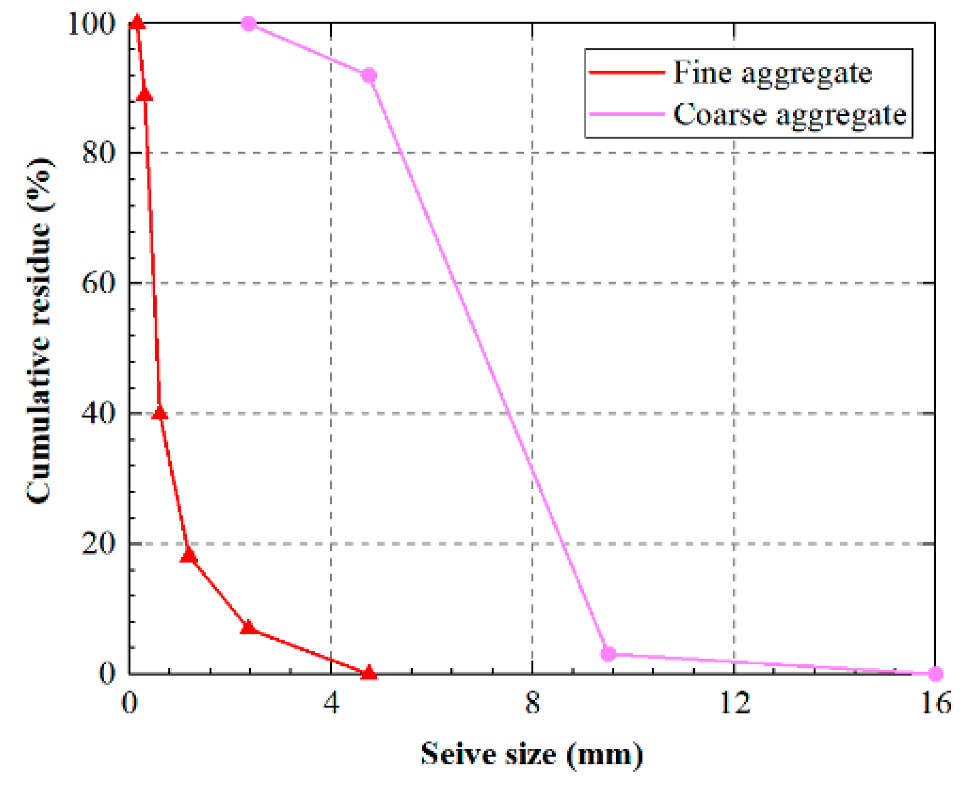
2.1. Raw Materials

Ordinary Portland cement (P.O 42.5R, specific gravity 3.112) served as the cementing material for concrete preparation. Seawater from Zhuhai, Guangdong Province, China, (specific gravity 1.003) was used. Sea sand, characterized by a medium grain size less than 4.75 mm, specific gravity 2.60, water content 3.36%, water absorption 4.27%, and fineness modulus 2.54, was employed as the fine aggregate. Crushed granites (particle size distribution of 5-10 mm, specific gravity of 2.64, water content of 1.39%, water absorption of 1.74%) were utilized as the coarse aggregate. The particle size distribution of both the fine and coarse aggregates is illustrated in Figure 1. The expansion agent predominantly consisted of calcium sulfoaluminate. An aqueous solution of the polycarboxylic acid base mixture (specific gravity 1.03, solids content 20%) was selected as the superplasticizer. Alkali-resistant glass fibers were used for the glass fibers. The glass fibers used had a length of 18 mm, density of 2680 kg/m3, elastic modulus of 72 GPa, and tensile strength of 1700 MPa.

2.2. Specimen Preparation

Seawater–sea-sand concrete was enhanced with an expansion agent and glass fibers, employing both single and combined methods to create reinforced concrete. According to the ISRM guidelines, the specimen thickness for the Brazilian splitting tensile test should ideally fall within the range of approximately 0.5 to 1 times the diameter [42]. Consequently, for the splitting tensile test in this study, the specimen size was specifically designed to be Ø100 × 50 mm.
To investigate the synergistic impact of the expansion agent and glass fibers under dynamic conditions, and drawing on previous research findings [27,33], specific admixture proportions were chosen. These included an expansion agent admixture (representing the ratio of expansion agent volume to the total volume of fine aggregate) set at 0% and 6%, and a glass fiber admixture (indicating the ratio of glass fiber volume to the total volume of concrete) at 0% and 1%. The water/cement (w/c) ratio was held constant at 0.40. Four distinct mix ratios of seawater–sea-sand concrete, designated as F-EA, were formulated. F0 and F1 signify glass fiber admixture proportions of 0% and 1%, while EA0 and EA6 represent expansion agent admixture proportions of 0% and 6%, as outlined in Table 1.

2.3. Testing Methods

2.3.1. Static Splitting Tensile Test

The static splitting tensile test device utilized a specialized fixture comprising a circular-shaped pad and a padded strip positioned between the upper and lower platens and the specimen. This fixture was aligned with the centerline and oriented perpendicular to the top surface of the molding. The specimen was placed at the center of the lower plate of the testing machine, ensuring that the splitting surface, or the splitting bearing surface, was perpendicular to the top surface of the specimen during formation. For loading, a test rate of 0.05 MPa/s (equivalent to a strain rate of approximately 1 × 10⁻⁵ s−1) was used. The static splitting tensile strength (fts) of the concrete was determined as follows:
f t s = 2 F t s π A
where Fts is the breaking load during splitting and stretching, and A is the area of the splitting surface of the specimen.

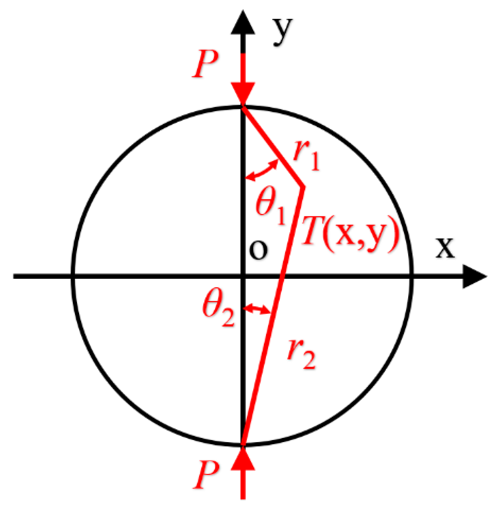
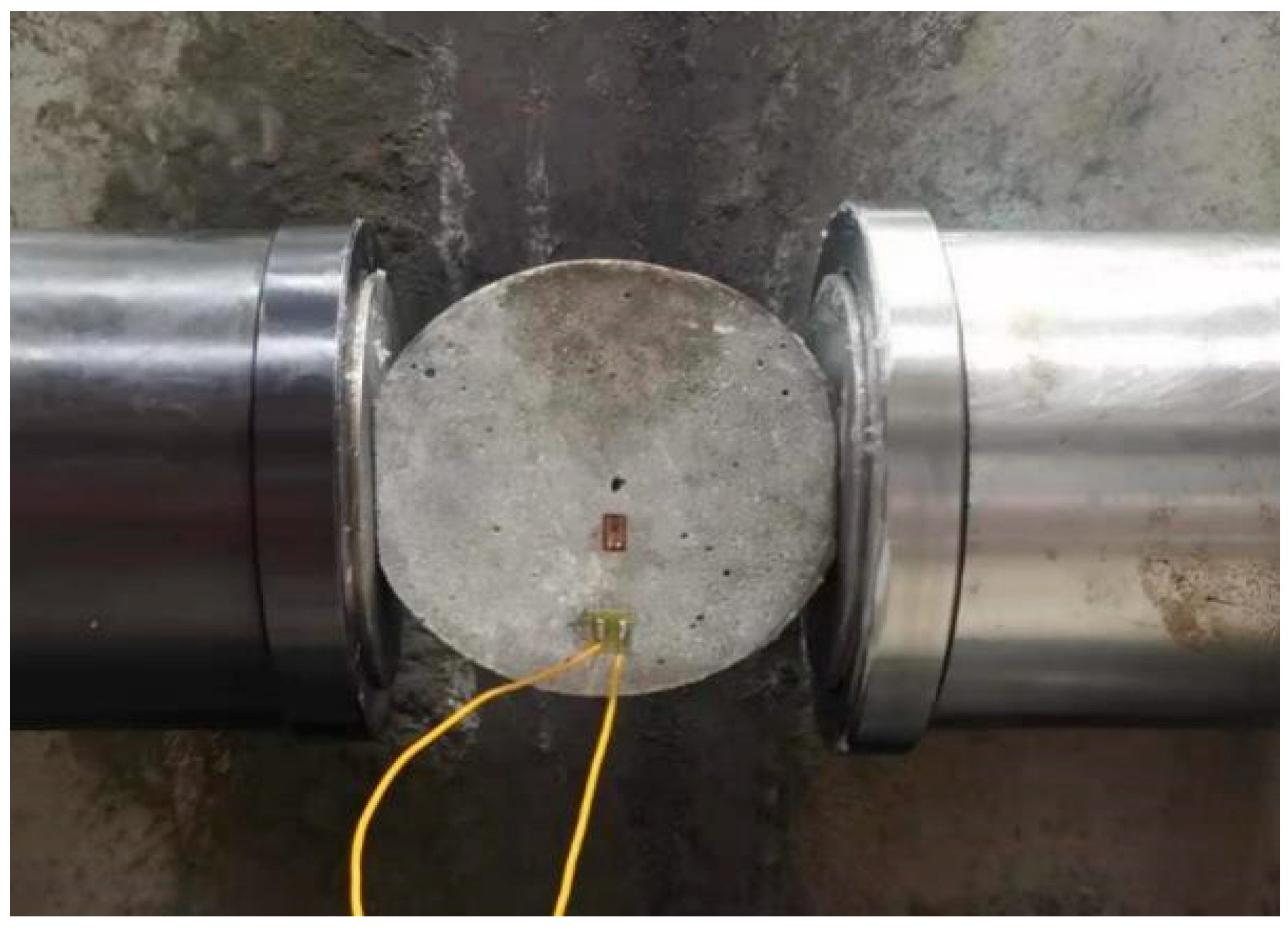
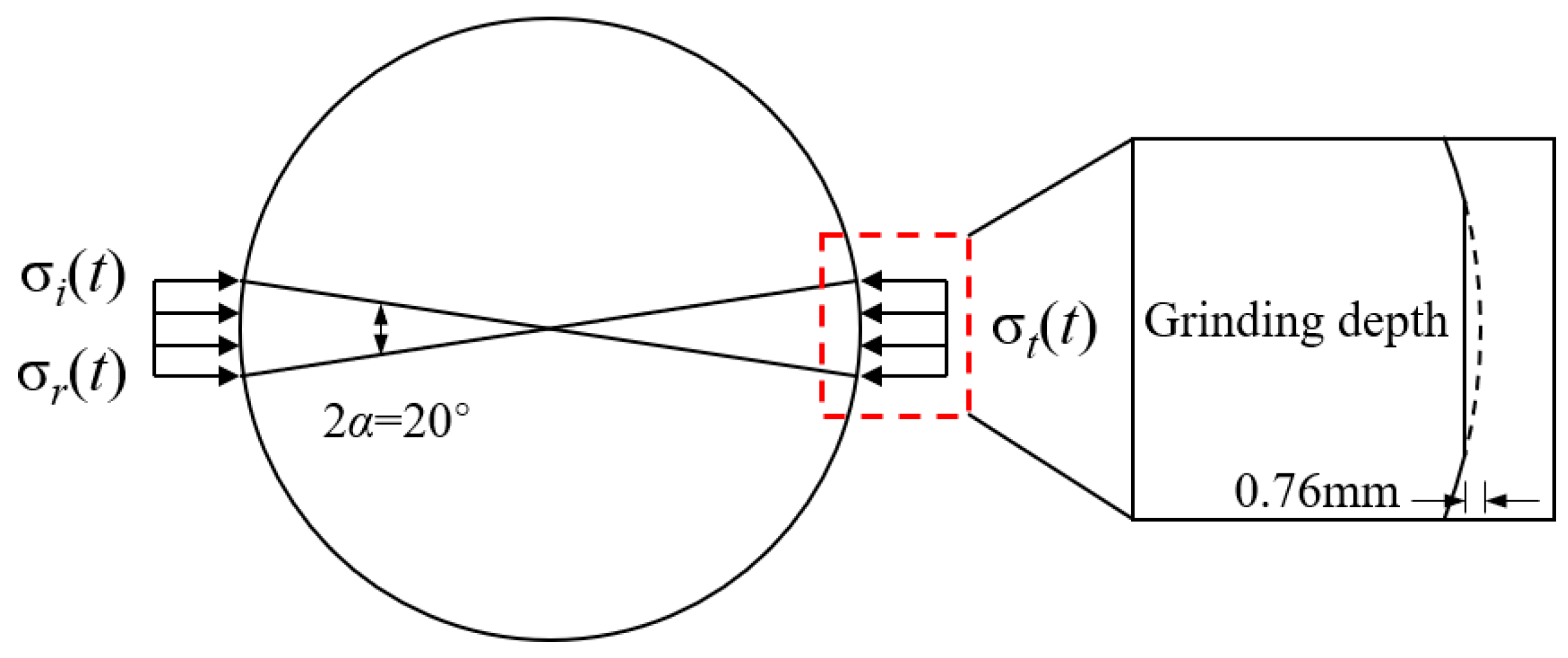
2.3.2. Dynamic Splitting Tensile Test

Brazilian disc splitting tests typically involve applying a relative linear load to the center of a cylindrical specimen. Following the principles of elastic mechanics, radial compression of the specimen induces horizontal tensile stress perpendicular to the center plane [42]. If this tensile stress surpasses the tensile strength of the material, the specimen fractures along its vertical midplane. The force analysis of the specimen in the Brazilian disc splitting test is illustrated in Figure 2.
The traditional Brazilian disc splitting strength formula in dynamic splitting tensile tests falls short of meeting the assumption of center crack initiation due to stress concentration at the loading end. Scholars have enhanced this formula [43,44] by introducing two platforms with central symmetry and mutual parallelism as the loading plane. This modification ensures that the crack originates from the center of the specimen during dynamic splitting tests. Following the findings of Wang et al. [45] and Huang et al. [46], the center angle of the platform was assumed to be 2α, and a correction factor (k) for the center tip of the platform was introduced. Specifically, when 2α = 20°, k was set to 0.95. Consequently, the dynamic splitting tensile strength of the Brazilian disc (ftd1) can be expressed as:
f t d 1 = 0.95 2 P π B D
where B and D are the thickness and diameter of the specimen, respectively, and P is the destructive load of the disk.
The dynamic Brazilian disc test was conducted using a Split Hopkinson Pressure Bar (SHPB), comprising test bars (a striker, an incident bar, and a transmitted bar), specimens, and a data acquisition system. Given the low tensile strength of concrete, semiconductor strain gauges were employed for the precise measurement of incident, reflected, and transmitted pulses. These strain gauges had a resistance of 120.0 ± 0.1 Ω and a sensitivity coefficient of 110 ± 5%. Two semiconductor strain gauges were affixed in the cross-section diameter direction of the incident and transmitted rods, forming a half-bridge to eliminate bending modes. Specifically, the strain gauges on the incident rods were positioned 2880 mm away from the specimen, while those on the transmitted rods were 1890 mm away, as illustrated in Figure 3. In addition, each specimen was fitted with an additional resistive strain gauge with a sensitive grid length of 5 mm, a resistance of 120.0 ± 0.1 Ω, and a sensitivity factor of 2.22 ± 1%. This gauge was strategically placed to capture the cracking moment at the center of the specimen during each test, facilitating the computation of the true split tensile strength, as depicted in Figure 4. The force–time scale (P(t)) during the test is represented as:
P ( t ) = E b A b 2 [ ε i ( t ) + ε r ( t ) + ε t ( t ) ]
where Eb and Ab are the modulus of elasticity and cross-sectional area of the bars in the SHPB device, respectively. εi(t) and εr(t) are the incident and reflected wave pulses captured by the strain gauges affixed to the incident bars, respectively. εt(t) is the transmitted wave pulse captured by the strain gauges attached to the transmission bars.
The force sketch for the dynamic Brazilian disk splitting test is shown in Figure 5, where σi(t), σr(t), and σt(t) are the stresses corresponding to εi(t), εr(t), and εt(t), respectively. A high-precision grinder with a parallelism accuracy of 0.01/300 mm and a smoothness accuracy of Ra 0.1 μm was used for grinding and processing. From the center angle of the platform to take 2α = 20°, the grinding depth of the platform was calculated to be 0.76 mm, and the parallelism error could be controlled within 0.02 mm. The SHPB test follows the one-dimensional stress wave assumption as well as the uniformity of the force applied to the specimen during the test:
σ i t + σ r t = σ t t
From Equations (2)–(4), the dynamic splitting tensile strength ftd of SHPB can be calculated as:
f t d = 0.95 2 σ t , m a x A 0 π D L
where σt,max is the peak value of the stress σt(t) corresponding to the transmitted wave pulse.
In the dynamic splitting test, the strain rate and dynamic enhancement factor (DIF) are important parameters used to evaluate the dynamic tensile properties of concrete. Equations (6) and (7) could be used to calculate the stress rate, strain rate, and DIF values of the specimens.
σ ˙ = f t d τ ;   ε ˙ = σ ˙ E 0
D I F = f t d f t s
In Equation (6), τ represents the time interval from the initial point to the peak value on the stress–time curve of the specimen, while E0 stands for the modulus of elasticity of the specimen. Studies have indicated [47] that the modulus of elasticity in concrete exhibits low sensitivity to strain rate, with the enhancement effect notably lower than that observed in compressive and tensile strengths. Consequently, in the current study, the static modulus of elasticity was employed for estimating the strain rate of the specimens.

3. Results and Discussion

3.1. Analysis of Results of Dynamic Splitting Tensile Test

Utilizing the F1EA6 set of specimens as an illustrative case, Figure 6 shows the dynamic response to the incident stress pulse. Notably, the peak stress σt,max corresponding to the transmitted wave pulse registered at 20.09 MPa. The stress between the starting point and the peak (τ) was approximately 315 μs, with a modulus of elasticity and thickness measuring 39.11 GPa and 50.74 mm, respectively. The SHPB device rod boasts a modulus of elasticity of 206 GPa. Referring to Equations (5)–(7) from Section 2.3, the dynamic splitting tensile strength of F1EA6-2 was calculated as 18.81 MPa, featuring a stress rate of 59.84 GPa/s and a strain rate of 1.53 s−1. This methodology is applicable across all specimens for determining the dynamic splitting tensile strength, stress rate, and strain rate. The test results for the SHPB dynamic splitting tensile specimens, encompassing four groups under five distinct approximate strain rates, are tabulated in Table 2.

3.2. Failure Mode

In Figure 7, the damage modes of four groups of SSC under varying approximate strain rates are illustrated. Following the SHPB dynamic splitting test, these SSC groups displayed evident cracking damage in the horizontal radial direction along the center, resulting in the final rupture into two parts. This damage mode aligns with prior studies on dynamic splitting tensile tests [48]. At a lower strain rate (around 1.10 s−1), the middle crack of the specimen was relatively small, dividing it into two halves along the developed crack. During this phase, the platform effectively served as a stress buffer. However, as the strain rate increased, the cracks of specimens gradually widened. At a strain rate of about 2.24 s−1, a broad horizontal crack emerged in the middle, accompanied by the appearance of crushing triangles at the platforms on both ends. Notably, there was a more extensive crushing area at the end in contact with the projectile rod. Importantly, the damage modes across all specimens did not exhibit a “T”-shaped three-piece split, consistent with findings in dynamic Brazilian disk splitting tests conducted on rock materials [49].
This study attributes the observed damage modes to the platforms at both ends of the specimen, which mitigate the stress concentration at the loaded contact end [50]. As the incident energy increases, the horizontal force on the platform intensifies, leading to a shorter duration of the shock wave acting on the specimen. Considering the brittle nature of concrete, rapid transmission of the stress wave and impact energy is essential near the end close to the incident pulse. Consequently, concrete produces multiple cracks to dissipate the impact energy, resulting in the eventual formation of a triangular crushing zone in the loading region after central cracking. It is noteworthy that at higher strain rates, the stress concentration at both ends of the specimen may impact the strain rate effect of the experiment.
A comparison of damage modes among the four groups of SSC at three different approximate strain rates (1.10 s−1, 1.79 s−1, and 2.24 s−1) indicates that at lower strain rates (1.10 s−1), the SSC groups with the expansion agent or glass fibers show greater damage mode integrity, in the following decreasing order of intactness: F1EA6, F1EA0, F0EA6, and F0EA0. Glass fiber incorporation was found to be more effective than the expansion agent in enhancing damage mode integrity. Conversely, at a higher strain rate (2.24 s−1), the damage integrity of the two groups of SSC with either the expansion agent or glass fibers alone was similar, while the SSC with a combination of the expansion agent and glass fibers outperformed the other three. The addition of glass fibers contributed to better toughening effects on SSC. However, this toughening development seemed to weaken at high strain rates. This might be attributed to the impact high energy and short duration, causing the glass fiber to slip and not fully exert its tensile properties. Among these, the damage mode of F1EA6 exhibited greater completeness, suggesting that the expansion agent can resist shrinkage within the concrete. It can even pre-pressurize the cement paste before external loading, resulting in a more compact contact between the glass fibers and cement paste. In essence, the combination of the expansion agent and glass fibers in SSC can better leverage the excellent tensile properties of glass fibers compared to glass fiber-reinforced concrete [20,39]. This enhancement contributes to improving the cracking strength and tensile strength of the concrete.

3.3. Overload Correction

Numerous studies have utilized an SHPB device to conduct dynamic Brazilian disc tests, examining the dynamic tensile characteristics of various rock and concrete materials [51,52]. However, some scholars [53,54] have observed that the dynamic Brazilian disc tensile strength tends to surpass the dynamic direct tensile strength based on test results. In their investigation of different rock materials, Zhang et al. [55] found that the dynamic increase factor (DIF) obtained from the Brazilian disc test was higher than that from direct tensile tests under similar loading rates. Similarly, Xia et al. [53] measured the dynamic tensile strength of granite using various testing methods, both direct and indirect, and discovered that the dynamic splitting tensile strength exceeded the dynamic direct tensile strength at equivalent loading rates. They concluded that this phenomenon results from overload effects and internal friction effects.
Hence, in the Brazilian disc test, it was observed [54] that the load-carrying capacity of specimens continued to increase even after tensile damage occurred at the center point, a phenomenon referred to as overload. To quantitatively analyze this overload effect, a strain gauge was affixed at a distance of d = 5 mm from the center of the specimen. The time difference in the acquired signal was then employed to capture the moment of dynamic splitting onset of the Brazilian disc specimen, enabling the determination of the tensile stress at the center point of the disc at the initiation of the splitting, as depicted in Figure 8. This approach was employed in the current study to address and correct the overload effect of the specimen.
In the dynamic tensile test utilizing the SHPB device, it is imperative to achieve dynamic force balance conditions at both ends of the specimen. The forces on the incident and transmitted bars and the specimen ends are denoted as P1 and P2. Only when the dynamic details at both ends of the specimen are balanced, and P1 equals P2, can the SHPB device be deemed valid. This ensures that the data collected by the strain gauges can be simplified and processed using Equation (2). Throughout this study, all specimens met the dynamic stress equilibrium criteria. Figure 9 illustrates the dynamic stress balance verification for a representative specimen, F1EA6-5.
According to Xia et al. [53], the initiation of cracking at the center of the disc prompts stress release in the surrounding region, leading to a notable inflection point in the strain gauge signal of the specimen. The moment corresponding to this inflection point signifies the cracking moment of the disk center. Assuming that tc represents the starting moment of the cracking of the disk center, the elastic wave speed of the specimen is known as c0, the elastic wave speed of the bar is cb = 5169 m/s, the diameter of the disk is D = 98.48 mm, and the distance between the strain gauges on the transmission bar and the left end is L = 1.89 m; then, the moment of the inflection point T1 of the captured signal by the strain gauge on the specimen is calculated as:
T 1 = t c + d c 0
By translating the transmitted signal according to the distance between the strain gauges on the transmission bar and the specimen center point, the corresponding moment T2 at which the center of the specimen starts to crack can be obtained as:
T 2 = t c + D 2 c 0 + L c b
Utilizing Equations (8) and (9), the strain gauge’s initial signal from the specimen serves as the reference point. By shifting the transmitted wave’s time-range signal to the left by |T2T1|, stress signals at both ends of the specimen can be computed. This process yields time-range signals of tension at the specimen ends, normalized against the cracking moment of the disc, facilitating the determination of tensile stresses at the center of disc at the point of cracking.
The calculation of a typical specimen (F1EA6-5) based on the above method yielded |T2T1| = 378 μs, and its tensile strength and crack initiation time-course signals after normalizing the time axis are shown in Figure 10. The peak value of the stress time-course curve of the specimen is defined as the nominal tensile strength ftd, and the overload-corrected strength is the true tensile strength ftd. Thus, we can calculate that the nominal tensile strength of F1EA6-5 was 23.98 MPa, and the true tensile strength was 17.34 MPa. In previous studies [50,55], it was found that the larger the loading rate, the more significant the difference between the stress at the moment of disc cracking initiation and the nominal tensile strength is, the more pronounced the overload phenomenon will be. Therefore, based on this method, the four groups of SSC were corrected for overloading, and after correction, the true tensile strengths of the specimens were determined and are shown in Table 2.
It can be found from Table 2 that there is a non-negligible difference between the nominal tensile strength ftd and the true tensile strength ftd′ of the four groups of SSC. To understand this phenomenon, we plotted the nominal tensile strength versus the true tensile strength in Figure 11 and found that the higher the loading rate, the larger the deviation of ftd from ftd′ is and the more pronounced the overload effect is. Therefore, the ftd obtained from the uncorrected overloaded Brazilian disc tests at higher strain rates is larger than ftd′ and does not truly reflect the material properties. In order to quantitatively analyze this degree of overloading, this study introduced S0 to denote the overload ratio of the specimen, which is calculated as:
S 0 = f t d f t d f t d
Using Equation (10), we calculated the overload ratios for the four groups of SSC, as detailed in Table 2. The correlation between the overload ratios and stress rates is illustrated in Figure 12. The overload ratios exhibited a logarithmic increase with the ascending stress rate, and their growth rate diminished gradually as the stress rate rose. Linear fitting of the experimental data resulted in a modified equation to represent the overload ratio of the compounded expansion agent and glass fiber-reinforced SSC, with the fitting parameters outlined in Table 3. The fitting outcomes highlight the highest linear fit correlation for F1EA6, reaching 0.928, and the trend of the overload ratio increasing with the strain rate followed a more logarithmic pattern. According to the fitting equation, it can be computed that the splitting tensile strength derived from the dynamic Brazilian disc test of compounded expansion agent and glass fiber-reinforced SSC would be overestimated by 38% when the stress rate is approximately 100 GPa/s. Therefore, its overload effect cannot be neglected.

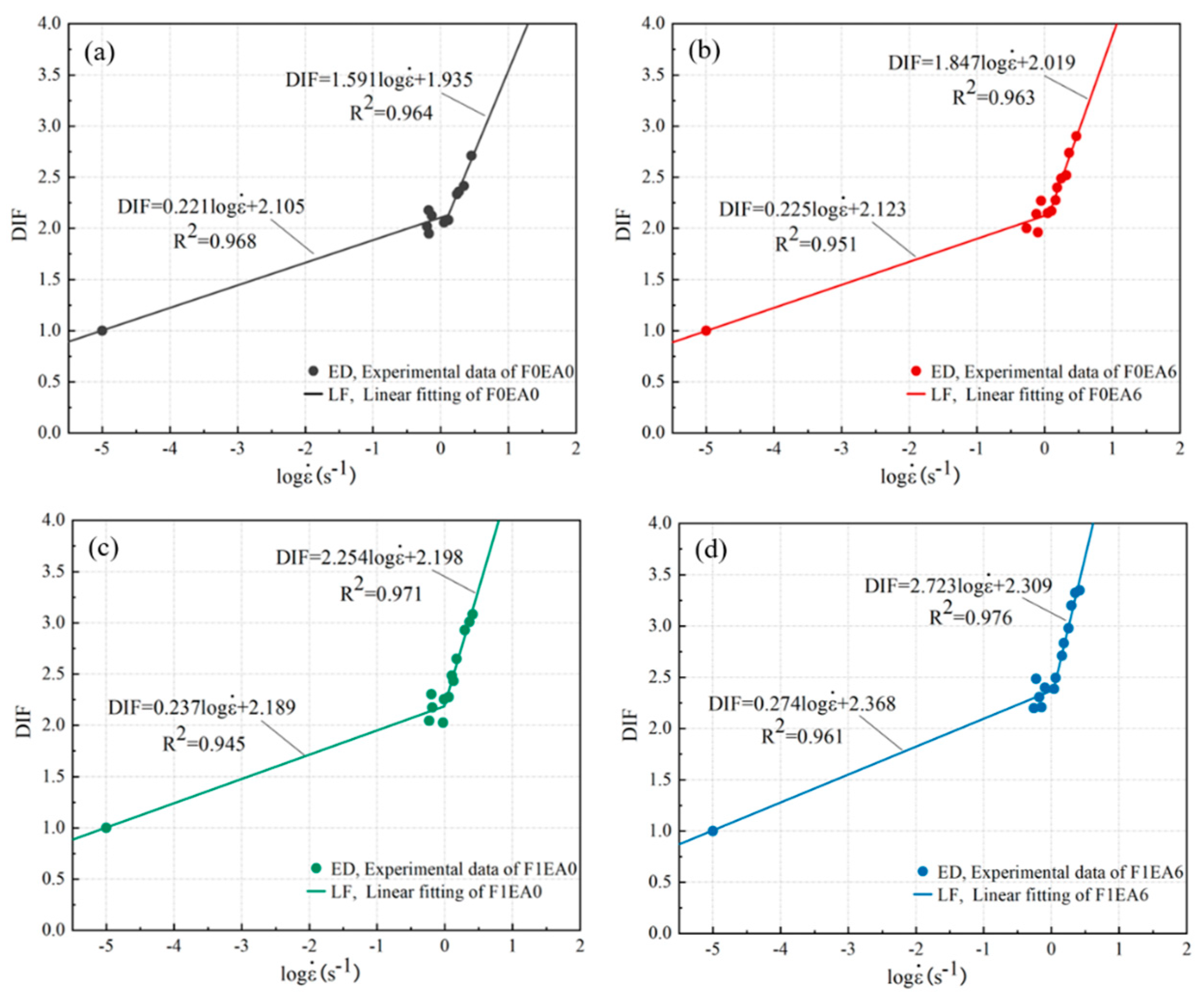
3.4. Strain Rate Effect

The DIF, serving as an indicator of the strain rate effect of concrete, exhibits an increasing trend with strain rate variations [47]. Table 2 illustrates the DIF values for the four SSC groups, revealing an augmentation of the DIF with escalating strain rates. Notably, F1EA6 boasted a higher DIF compared to the other groups at equivalent strain rates, underscoring the pronounced strain rate effect in the mixed expansion agent and glass fiber-reinforced SSC.
In a comprehensive synthesis of the literature and experimental findings, Zhou et al. [56] established a logarithmic relationship between the DIF and concrete strain rate. This relationship is divided into two segments to delineate below-critical strain rates (Equation (11)) and above-critical strain rates (Equation (12)) [55]:
D I F = a log ε ˙ + b ;   ε ˙ ε i ˙
D I F = c log ε ˙ + d ;   ε ˙ > ε i ˙
where ε i ˙ is the critical strain rate, and a, b, c, and d are the fitting parameters.
The overload-corrected Dynamic Increase Factor (DIF) plotted against the logarithmic strain rate for the four groups of SSC has been fitted using Equations (11) and (12), and is depicted in Figure 13. The fitted parameter values are detailed in Table 4. The critical strain rates for these groups fall within the range of 1.06–1.31 s−1, aligning with the critical strain rate observed in ordinary concrete, approximately 1.00 s−1 [57]. Notably, the slopes of the fitted curves for the four SSC groups exhibited a considerable increase in the high critical strain rate stage compared to the low critical strain rate stage. This observation suggests that the strain rate effect on the dynamic splitting behavior becomes more pronounced at higher strain rates, consistent with prior research findings [58]. At below-critical strain rates, the strain rate effect on expansion agent and glass fiber-reinforced SSC was minimal, with the dynamic splitting tensile strength experiencing gradual growth with increasing strain rate. However, at above-critical strain rates, the strain rate sensitivity of the SSC significantly intensified, revealing a robust rate sensitivity. This heightened sensitivity may be attributed to the synergistic impact of the expansion agent and glass fibers. The expansion agent’s compacting effect enhances the bond between glass fibers and mortar interfaces, allowing the glass fibers to optimize their properties. Simultaneously, the concrete experiences internal pre-pressure, enabling the glass fibers to withstand external forces with pre-tension. This comprehensive enhancement contributes to improved crack resistance and tensile properties for the concrete.

3.5. Energy Dissipation Analysis

In the dynamic splitting test, the splitting damage mechanism of specimens involves the absorption and release of energy. Impact loading is typically characterized by a short duration and high energy. Effective impact resistance requires the material to exhibit superior energy dissipation capabilities under such loading conditions. The axial strain observed in dynamic splitting tests is a non-uniform strain. To quantify the energy dissipation capacity of brittle specimens under dynamic splitting tensile tests using a Split Hopkinson Pressure Bar (SHPB), Song et al. [59] introduced the concept of energy dissipation, denoted as Ws(t). This measure is derived by subtracting the reflected wave energy (Wr(t)) from the total incident wave energy (Wi(t)), with the transmitted wave energy (Wt(t)) contributing to the calculation, as shown in Equation (13). The specific calculations for Wi(t), Wr(t), and Wt(t) are detailed in Equation (14), Equation (15), and Equation (16), respectively.
W s ( t ) = W i ( t ) - W r ( t ) - W t ( t )
W i ( t ) = E b C b A b 0 t ε i 2 ( t ) d t
W r ( t ) = E b C b A b 0 t ε r 2 ( t ) d t
W t ( t ) = E b C b A b 0 t ε t 2 ( t ) d t
where Eb is the modulus of elasticity of the bar of the SHPB device, Cb is the elastic wave velocity of the bar, and Ab is the cross-sectional area of the bar.
Table 5 summarizes the maximum values of Wi(t), Wr(t), Wt(t), and Ws(t), denoted as Wi, Wr, Wt, and Ws, respectively, reflecting the peak energy dissipation in the dynamic splitting tensile test for the four SSC groups. The table provides details on the incident, reflected, and transmitted energies, along with the energy dissipation and absorption under various impact loads. The energy dissipation ratio (Ws/Wi), defined as the ratio of transmitted energy (Ws) to incident energy (Wi), is crucial for understanding the dynamic behavior of the specimens. At a high impact energy, the energy dissipation ratio tended to decrease with increasing incident energy (Wi). This phenomenon is attributed to the short damage time of the specimen at high strain rates, leading to increased brittleness in concrete as the impact energy rises [58]. A higher energy dissipation ratio signifies that the specimen absorbed more energy during impact.
The energy consumption ratio curves for the four groups of single or mixed expansion agent and glass fiber-reinforced SSC are depicted in Figure 14. At similar impact energy levels, the energy consumption ratio of the mixed expansion agent and glass fiber-reinforced SSC surpasses that of the other three groups. This outcome underscores the superior ability of the expansion agent and glass fiber-reinforced SSC to cushion and dissipate energy when exposed to impact loads in comparison to the other groups. This finding aligns with prior research indicating that fiber admixtures enhance concrete crack resistance and improve energy absorption efficiency [60]. The synergistic effect between the compounded expansion agent and glass fibers further enhances the energy dissipation capacity of the glass fiber. Moreover, the trend of the energy dissipation ratio curves for the four SSC groups revealed a decline with increasing impact energy. This suggests that at high strain rates, the damage time of the specimens is exceedingly brief, rendering the SSC more brittle when subjected to elevated impact energies.

3.6. Limitations and Prospects

In this work, the authors initially investigated the effects of single and mixed admixtures of expansion agent and glass fibers in seawater–sea-sand concrete on the concrete’s dynamic splitting properties. Based on the results of the splitting tensile experiments under static and impact conditions, it can be concluded that a mixed admixture of expansion agent and glass fiber can enhance the internal structure of concrete and improve the overall tensile strength, impact toughness, and energy dissipation capacity. To this end, the advantages and limitations of this study are summarized in Table 6. However, there are some limitations of these research results.
While this study delved into the dynamic splitting performance of composite seawater–sea-sand concrete, specifically focusing on damage mode, strain rate effects, and energy dissipation capacity, it did not thoroughly explore the microscopic aspects of the dynamic damage process and the changing pattern of crack formation. In essence, the analysis was macroscopic, covering the damage mode and stress changes under dynamic splitting. Future research could provide a more comprehensive understanding by employing SEM, DIC, and other technical methods to scrutinize the dynamic damage mode and crack expansion under different strain rates. This microscopic perspective would offer a more realistic and concrete portrayal of the dynamic splitting performance of the expansion agent and glass fiber-reinforced seawater–sea-sand concrete.
In this study, an SHPB device was employed to conduct dynamic Brazilian disc tests. The measured dynamic tensile strengths in the indirect Brazilian disc tests tended to surpass the dynamic direct tensile strengths, indicating an observed overloading phenomenon. This overload effect was particularly pronounced at higher strain rates. To address this, the study focused on capturing the central cracking moment by analyzing the time difference in acquired signals, allowing for the determination of tensile stress at the disc center point at the cracking moment. The overload effect was quantitatively analyzed by setting the overload ratio to obtain the true tensile strength. While the overload correction of the dynamic tensile strength is feasible experimentally and yields conclusions, certain practical deficiencies exist. These include an incomplete reflection of the real damage morphology in the damage process, the omission of friction in the simulation process, and the oversight of specimen defects. The subsequent research should delve into the dynamic damage process and crack extension laws from a microscopic perspective, supplementing the numerical analysis of microscopic models and comparing them with experimental tests. Meanwhile, the dynamic splitting performance of expansion agent and glass fiber-reinforced seawater–sea-sand concrete remains in the laboratory research stage. Further investigations should extend the research to practical applications in engineering.

4. Conclusions

In this study, four sets of seawater–sea-sand concrete (SSC) mixtures with varying ratios were designed to explore the impact of single and combined admixtures of expansion agent and glass fibers on the dynamic splitting properties of SSC. The primary conclusions drawn from the results of the static and impact splitting tensile experiments are as follows:
(1)
The damage modes of the four groups of SSC at three different approximate strain rates all exhibited clear horizontal radial cracking along the center, which was less pronounced at lower strain rates. Nevertheless, the cracks in the specimens gradually widened with increasing strain rates. At low strain rates (1.10 s−1), the incorporation of glass fibers proved to be more effective than the addition of the expansion agent in enhancing damage modal integrity. However, at a high strain rate (2.24 s−1), the SSC with the combined admixture of expansion agent and glass fibers demonstrated better damage modal integrity than the other three groups.
(2)
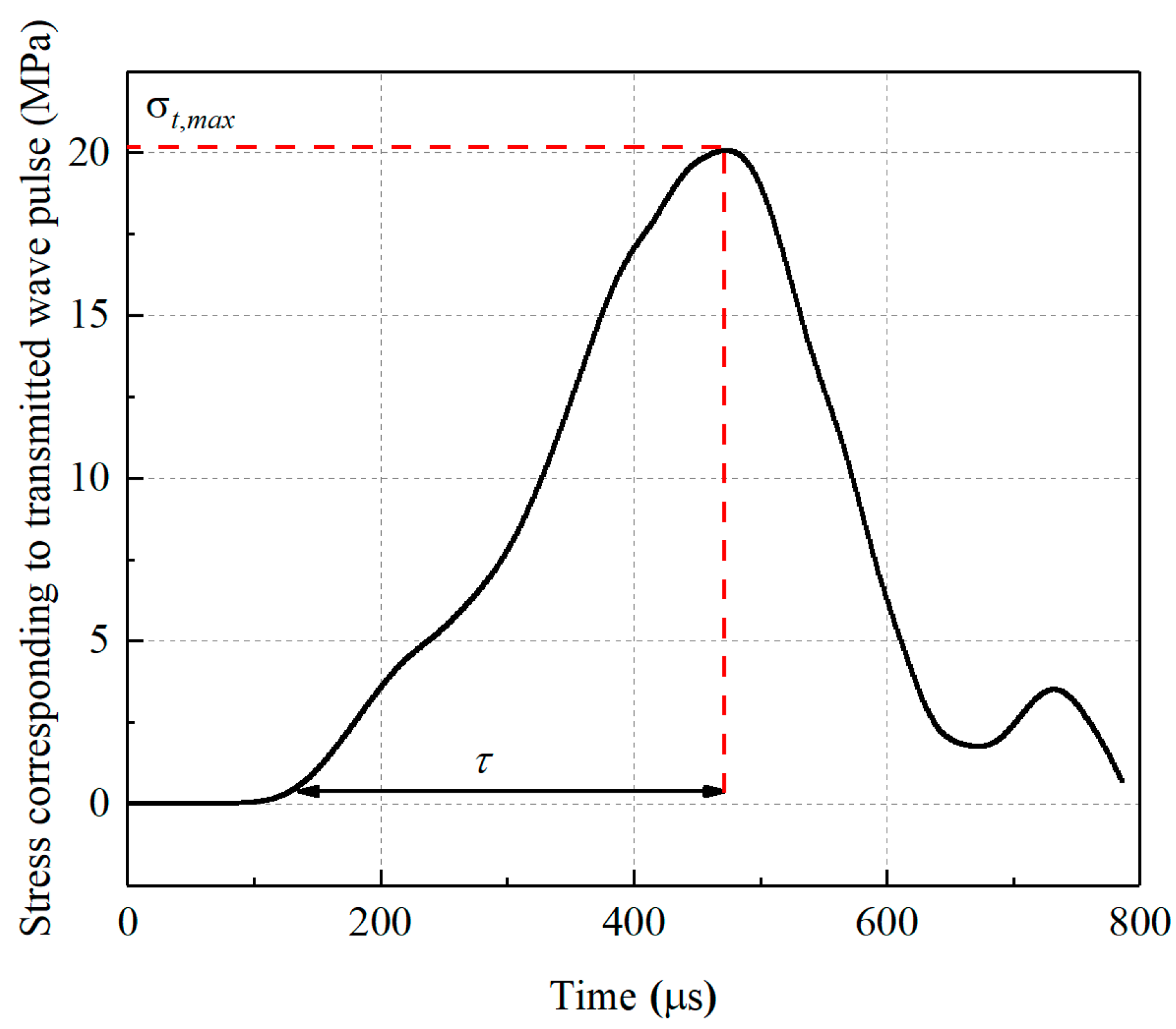
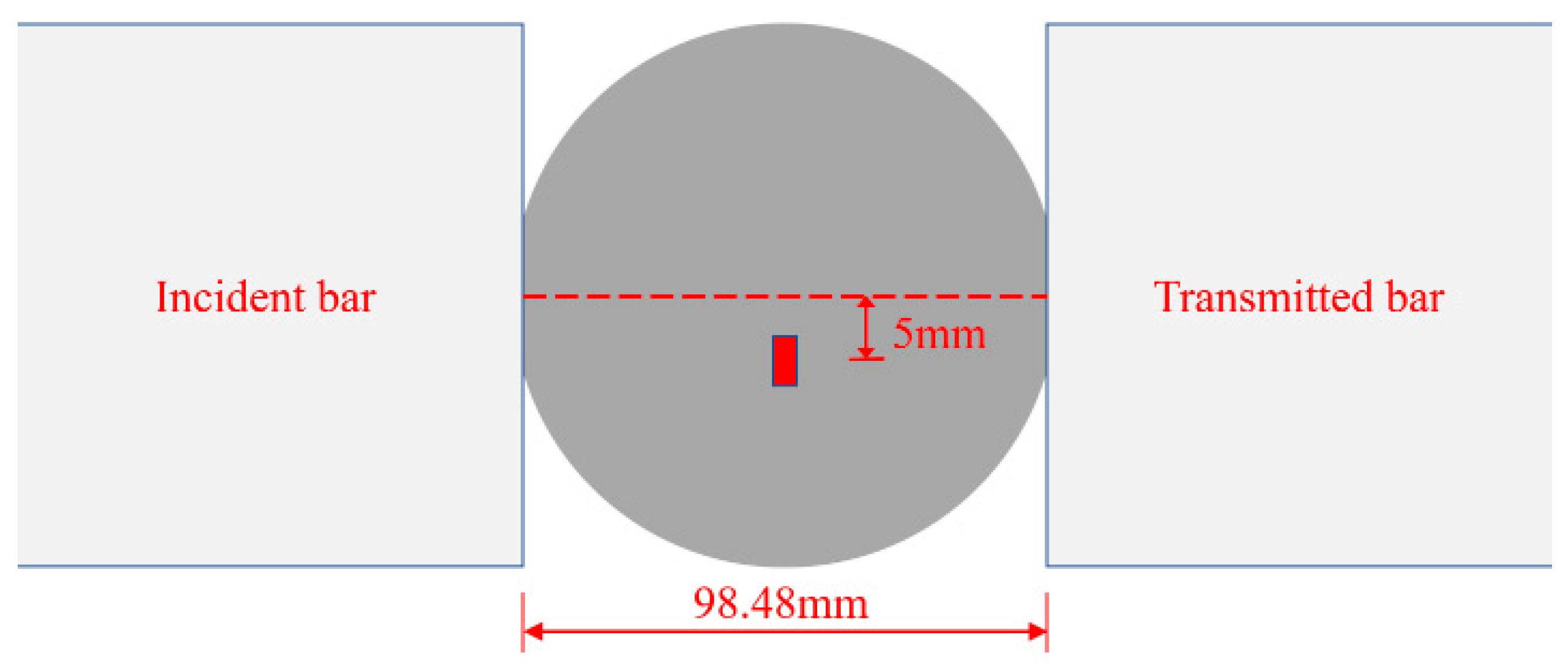
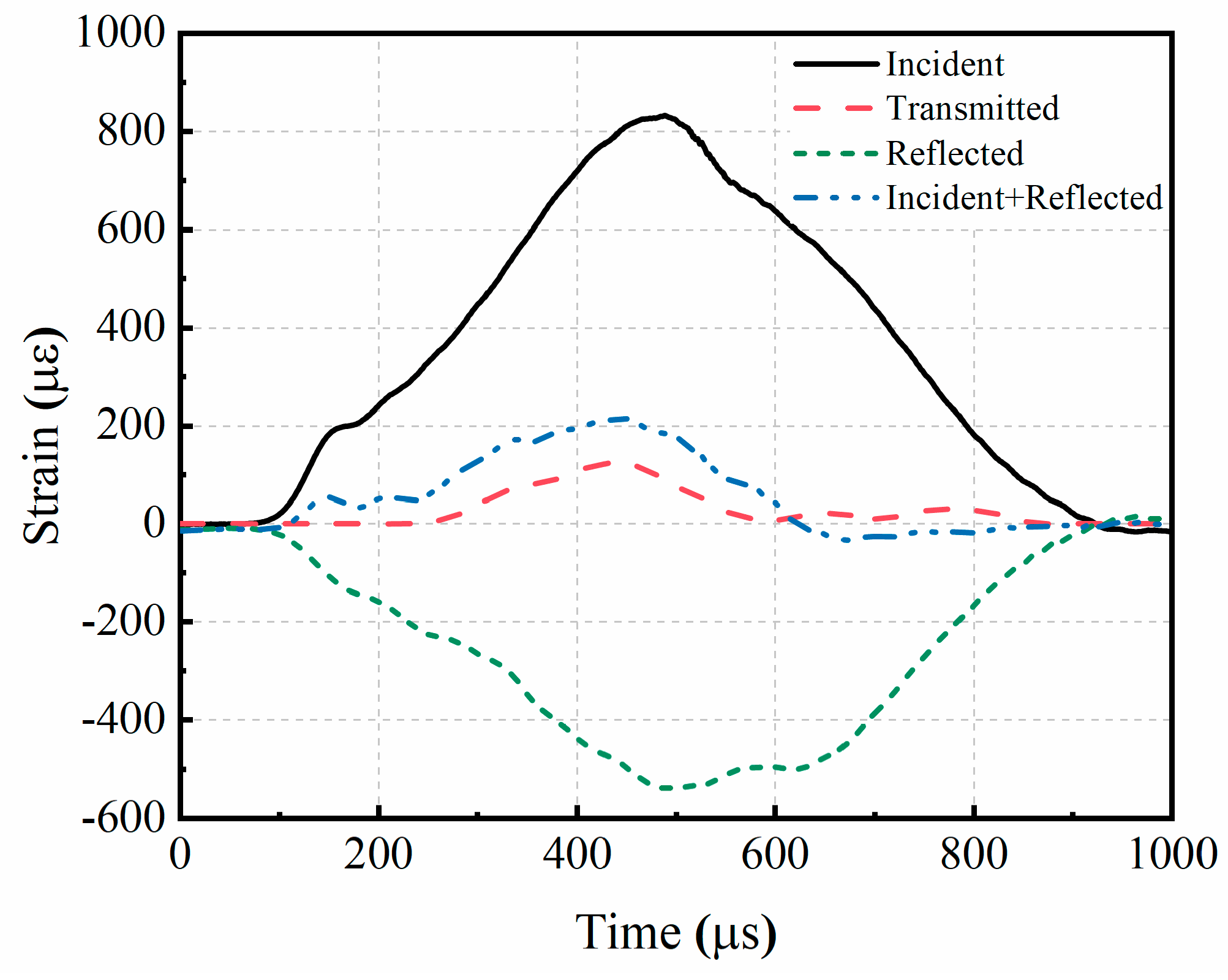
The dynamic splitting tensile strength of the four SSC groups, as measured in the dynamic Brazilian disc test, exhibited significant overload, with higher strain rates amplifying the overload effect. To monitor crack initiation at the center of the disc and correct for overload, strain gauges were strategically placed. The overload ratio, denoted as S0, was introduced for the quantitative analysis. The overload ratio displayed a logarithmic increase with the stress rate. When the stress rate reached approximately 100 GPa/s, the measured dynamic splitting tensile strength of the mixed expansion agent and glass fiber-reinforced SSC was overestimated by 38%. At this point, the overload effect became substantial and cannot be overlooked.
(3)
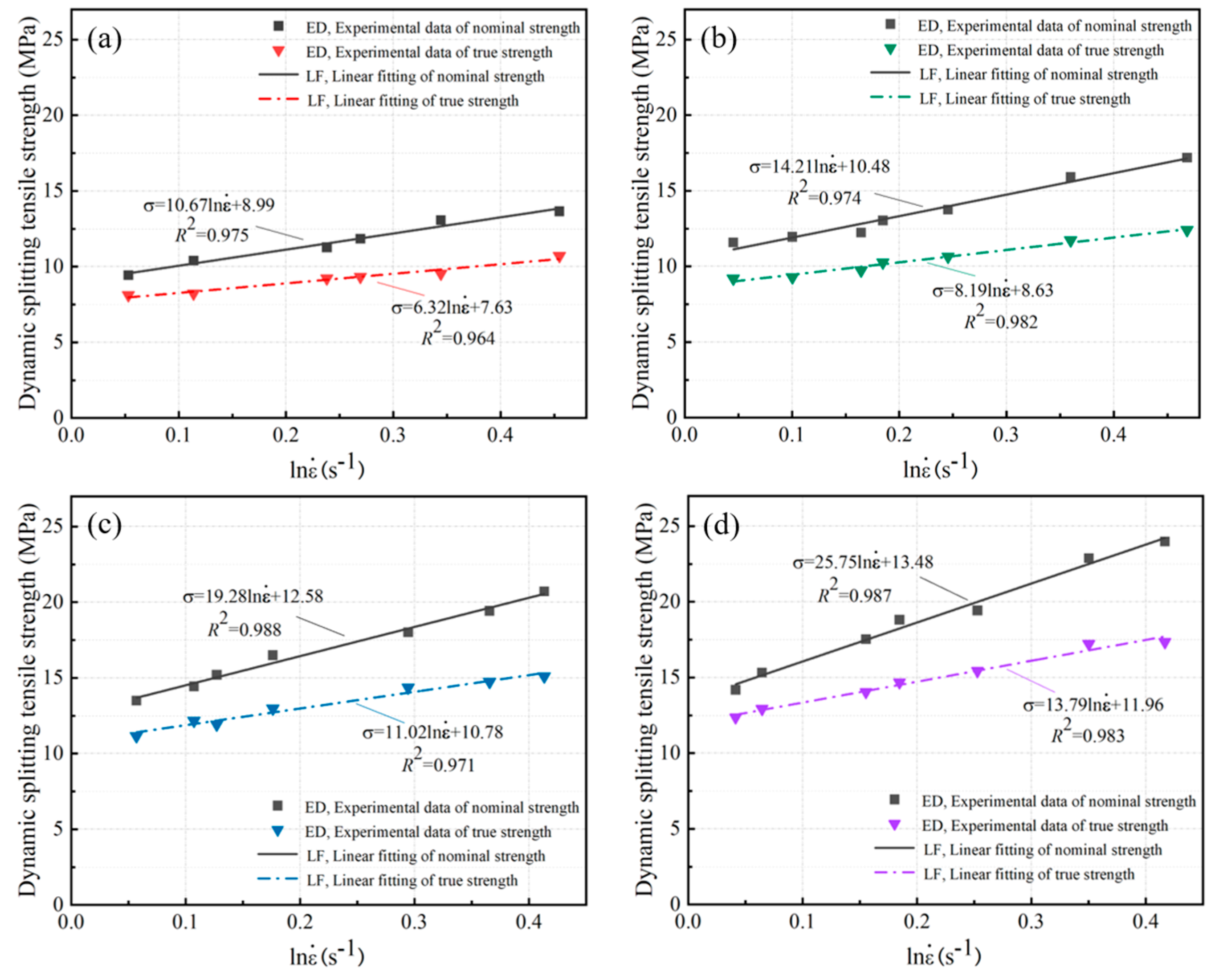
The critical strain rates for the four SSC groups fell within the range of 1.06–1.31 s−1, similar to the critical strain rate of ordinary concrete, which is approximately 1.00 s−1. At below-critical strain rates, the strain rate effect of the mixed expansion agent and glass fiber-reinforced SSC was negligible. However, at above-critical strain rates, the specimens exhibited a significant strain rate effect, demonstrating heightened sensitivity, particularly showcasing a robust rate sensitivity.
(4)
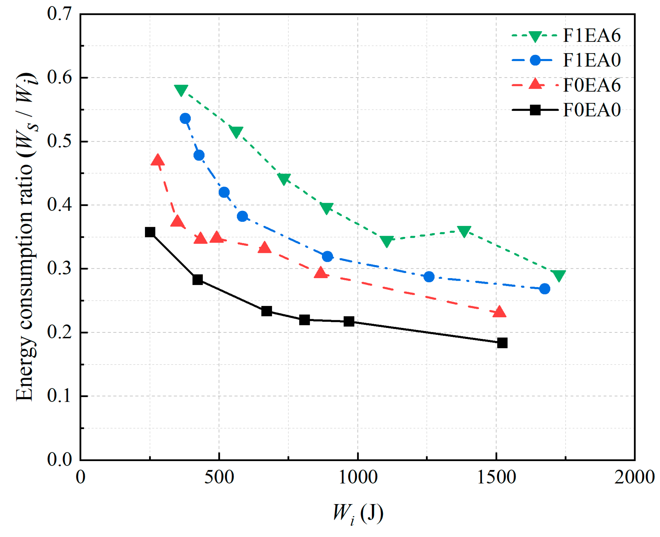
The energy dissipation ratio of the mixed expansion agent and glass fiber-reinforced SSC surpasses that of the other three groups at comparable impact energy levels. The synergistic effect between the expansion agent and glass fiber contributed to superior cushioning and energy dissipation under impact loading. The energy consumption ratio curves for the four SSC groups showed a decreasing trend with escalating impact energy. This indicates that SSC becomes more brittle when subjected to higher impact energy levels.
(5)
At present, the research on the mechanical properties of seawater–sea-sand concrete is still based on compressive strength; in comparison, the investigation of tensile strength has received less research interest. However, the research on the synergistic reinforcement effect of expansion agents and fibers is still based on static mechanical properties, with the dynamic impact property receiving less research interest. Using static loading methods may not authentically reflect the dynamic splitting tensile properties of concrete. Therefore, the SHPB device was employed in this study to conduct Brazilian disc tests. The tested nominal tensile strength was corrected for overload using a quantitative analysis to obtain the true tensile strength. Investigating the dynamic tensile properties of the expansion agent and glass fiber-reinforced seawater–sea-sand concrete under impact can support the development of seawater–sea-sand concrete with excellent dynamic splitting tensile properties.

Author Contributions

Conceptualization, H.Z., Z.X. and Y.S. (Yuying Song); Data curation, Y.S. (Yuying Song), K.Z. and Y.S. (Yue Su); Formal analysis, H.Z. and Z.X.; Funding acquisition, Z.X.; Investigation, K.Z. and Y.S. (Yue Su); Methodology, Y.S. (Yuying Song) and Z.X.; Project administration, Z.X.; Resources, Z.X.; Software, H.Z.; Supervision, Z.X.; Writing—original draft, K.Z. and Y.S. (Yuying Song); Writing—review and editing, H.Z. and Y.S. (Yuying Song). All authors have read and agreed to the published version of the manuscript.

Funding

This research was funded by the National Natural Science Foundation of China under Grants No. 12032009 and No. 12002091.

Data Availability Statement

The original data are available upon request. The data are not publicly available due to project privacy.

Acknowledgments

The authors thank all the technical personnel from the Structural Laboratory of Guangdong University of Technology for their assistance during the experiments.

Conflicts of Interest

The authors declare no conflicts of interest.

References

  1. Nham, N.T.H.; Ha, L.T. The role of financial development in improving marine living resources towards sustainable blue economy. J. Sea Res. 2023, 195, 102417. [Google Scholar] [CrossRef]
  2. Jiang, S.-S.; Li, J.-M. Exploring the motivation and effect of government-enterprise collusion in the utilization of marine resources: Evidence from China’s coastal areas. Ocean. Coast. Manag. 2021, 212, 105822. [Google Scholar] [CrossRef]
  3. Yang, Z.; Zhan, X.; Zhu, H.; Zhang, B.; Feng, P.; Li, H.; Kua, H.W. Performance-based alkali-activated seawater sea-sand concrete: Mixture optimization for mechanical, environmental, and economical objectives. Constr. Build. Mater. 2023, 409, 134156. [Google Scholar] [CrossRef]
  4. Liu, X.; Asghari, V.; Lam, C.-M.; Hsu, S.-C.; Xuan, D.; Angulo, S.C.; John, V.M.; Basavaraj, A.S.; Gettu, R.; Xiao, J.; et al. Discrepancies in life cycle assessment applied to concrete waste recycling: A structured review. J. Clean. Prod. 2024, 434, 140155. [Google Scholar] [CrossRef]
  5. Tayebani, B.; Said, A.; Memari, A. Less carbon producing sustainable concrete from environmental and performance perspectives: A review. Constr. Build. Mater. 2023, 404, 133234. [Google Scholar] [CrossRef]
  6. Liu, F.; Zhang, J.; Sun, J.; Zhao, D.; Gao, D.; Ma, Z.; Song, H.; Wu, R.; Zhang, W. The ice resistance of self-centering jacket offshore platform with concrete filled double-skin legs: Experimental study and numerical analysis. Ocean Eng. 2023, 287, 115876. [Google Scholar] [CrossRef]
  7. Jiang, S.; Chen, G.; Zhu, Y.; Li, X.; Shen, X.; He, R. Real-time risk assessment of explosion on offshore platform using Bayesian network and CFD. J. Loss Prev. Process. Ind. 2021, 72, 104518. [Google Scholar] [CrossRef]
  8. Demirci, S.E.; Elçiçek, H. Scientific awareness of marine accidents in Europe: A bibliometric and correspondence analysis. Accid. Anal. Prev. 2023, 190, 107166. [Google Scholar] [CrossRef]
  9. Yan, Z.-W.; Bai, Y.-L.; Ozbakkaloglu, T.; Gao, W.-Y.; Zeng, J.-J. Rate-dependent compressive behavior of concrete confined with Large-Rupture-Strain (LRS) FRP. Compos. Struct. 2021, 272, 114199. [Google Scholar] [CrossRef]
  10. Bai, Y.-L.; Yan, Z.-W.; Ozbakkaloglu, T.; Gao, W.-Y.; Zeng, J.-J. Mechanical behavior of large-rupture-strain (LRS) polyethylene naphthalene fiber bundles at different strain rates and temperatures. Constr. Build. Mater. 2021, 297, 123786. [Google Scholar] [CrossRef]
  11. Yan, Z.-W.; Bai, Y.-L.; Ozbakkaloglu, T.; Gao, W.-Y.; Zeng, J.-J. Axial impact behavior of Large-Rupture-Strain (LRS) fiber reinforced polymer (FRP)-confined concrete cylinders. Compos. Struct. 2021, 276, 114563. [Google Scholar] [CrossRef]
  12. Xiang, J.; Qiu, J.; Zhao, Y.; Zheng, P.; Peng, H.; Fei, X. Rheology, mechanical properties, and hydration of synergistically activated coal gasification slag with three typical solid wastes. Cem. Concr. Compos. 2024, 147, 105418. [Google Scholar] [CrossRef]
  13. Yang, L.; Xie, H.; Zhang, D.; Zhang, F.; Lin, C.; Fang, S. Acoustic emission characteristics and crack resistance of basalt fiber reinforced concrete under tensile load. Constr. Build. Mater. 2021, 312, 125442. [Google Scholar] [CrossRef]
  14. Xiang, J.; Qiu, J.; Wu, P.; Zhang, Q.; Song, Y.; Yang, L. Autolytic capsules incorporating alkali-activated slag system for self-healing cementitious composites. Cem. Concr. Compos. 2024, 105439. [Google Scholar] [CrossRef]
  15. Liang, N.; Geng, S.; Mao, J.; Liu, X.; Zhou, X. Investigation on cracking resistance mechanism of basalt-polypropylene fiber reinforced concrete based on SEM test. Constr. Build. Mater. 2024, 411, 134102. [Google Scholar] [CrossRef]
  16. Zhen, H.; Xiong, Z.; Song, Y.; Li, L.; Qiu, Y.; Zou, X.; Chen, B.; Chen, D.; Liu, F.; Ji, Y. Early mechanical performance of glass fibre-reinforced manufactured sand concrete. J. Build. Eng. 2024, 83, 108440. [Google Scholar] [CrossRef]
  17. Ahmed, S.; Ali, M. Use of agriculture waste as short discrete fibers and glass-fiber-reinforced-polymer rebars in concrete walls for enhancing impact resistance. J. Clean. Prod. 2020, 268, 122211. [Google Scholar] [CrossRef]
  18. Wang, W.; Zhang, Y.; Mo, Z.; Chouw, N.; Jayaraman, K.; Xu, Z.-D. A critical review on the properties of natural fibre reinforced concrete composites subjected to impact loading. J. Build. Eng. 2023, 77, 107497. [Google Scholar] [CrossRef]
  19. Xie, C.; Cao, M.; Khan, M.; Yin, H.; Guan, J. Review on different testing methods and factors affecting fracture properties of fiber reinforced cementitious composites. Constr. Build. Mater. 2021, 273, 121766. [Google Scholar] [CrossRef]
  20. Mastali, M.; Dalvand, A.; Sattarifard, A. The impact resistance and mechanical properties of reinforced self-compacting concrete with recycled glass fibre reinforced polymers. J. Clean. Prod. 2016, 124, 312–324. [Google Scholar] [CrossRef]
  21. Liu, L.; Wang, X. Research on test of alkali-resistant glass fibre enhanced seawater coral aggregate concrete. In Proceedings of the 1st International Conference on Frontiers of Materials Synthesis and Processing (FMSP 2017), Changsha, China, 28–29 October 2017. [Google Scholar]
  22. Sun, W.; Chen, H.; Luo, X.; Qian, H. The effect of hybrid fibers and expansive agent on the shrinkage and permeability of high-performance concrete. Cem. Concr. Res. 2001, 31, 595–601. [Google Scholar] [CrossRef]
  23. Fan, Q.; Fan, L.; Quach, W.-M.; Zhang, R.; Duan, J.; Sand, W. Application of microbial mineralization technology for marine concrete crack repair: A review. J. Build. Eng. 2023, 69, 106299. [Google Scholar] [CrossRef]
  24. Liu, K.; Shui, Z.; Sun, T.; Ling, G.; Li, X.; Cheng, S. Effects of combined expansive agents and supplementary cementitious materials on the mechanical properties, shrinkage and chloride penetration of self-compacting concrete. Constr. Build. Mater. 2019, 211, 120–129. [Google Scholar] [CrossRef]
  25. Mo, L.; Deng, M.; Tang, M.; Al-Tabbaa, A. MgO expansive cement and concrete in China: Past, present and future. Cem. Concr. Res. 2014, 57, 1–12. [Google Scholar] [CrossRef]
  26. Wang, A.G.; Deng, M.; Sun, D.S.; Mo, L.W.; Wang, J.; Tang, M.S. Effect of Combination of Steel Fiber and MgO-type Expansive Agent on Properties of Concrete. J. Wuhan Univ. Technol. -Mater. Sci. Ed. 2011, 26, 786–790. [Google Scholar] [CrossRef]
  27. Xiong, Z.; He, S.; Kwan, A.; Li, L.; Zeng, Y. Compressive behaviour of seawater sea-sand concrete containing glass fibres and expansive agents. Constr. Build. Mater. 2021, 292, 123309. [Google Scholar] [CrossRef]
  28. Yang, G.; Zhao, J.; Wang, Y. Durability properties of sustainable alkali-activated cementitious materials as marine engineering material: A review. Mater. Today Sustain. 2022, 17, 100099. [Google Scholar] [CrossRef]
  29. Li, Y.; Chen, G.; Yang, Z.; Li, Y.; Xu, M. Experimental study on the reaction process and engineering characteristics of marine calcareous sand reinforced by eco-friendly methods. Appl. Ocean Res. 2023, 138, 103641. [Google Scholar] [CrossRef]
  30. Xiao, J.; Qiang, C.; Nanni, A.; Zhang, K. Use of sea-sand and seawater in concrete construction: Current status and future opportunities. Constr. Build. Mater. 2017, 155, 1101–1111. [Google Scholar] [CrossRef]
  31. Zhao, Y.; Hu, X.; Shi, C.; Zhang, Z.; Zhu, D. A review on seawater sea-sand concrete: Mixture proportion, hydration, microstructure and properties. Constr. Build. Mater. 2021, 295, 123602. [Google Scholar] [CrossRef]
  32. Xiang, J.; Qiu, J.; Li, Z.; Chen, J.; Song, Y. Eco-friendly treatment for MSWI bottom ash applied to supplementary cementing: Mechanical properties and heavy metal leaching concentration evaluation. Constr. Build. Mater. 2022, 327, 127012. [Google Scholar] [CrossRef]
  33. Su, Y.; Xiong, Z.; Hu, Z.; Zhu, W.; Zhou, K.; Wang, J.; Liu, F.; Li, L. Dynamic bending study of glass fiber reinforced seawater and sea-sand concrete incorporated with expansive agents. Constr. Build. Mater. 2022, 358, 129415. [Google Scholar] [CrossRef]
  34. Xiong, Z.; Zeng, Y.; Li, L.; Kwan, A.; He, S. Experimental study on the effects of glass fibres and expansive agent on the bond behaviour of glass/basalt FRP bars in seawater sea-sand concrete. Constr. Build. Mater. 2021, 274, 122100. [Google Scholar] [CrossRef]
  35. Chen, L.; Zhou, Q.; Yue, L.; Wu, M.; Huang, R.; Yuen, K.F.; Su, R. A theoretical model for preventing marine litter behaviour: An empirical evidence from Singapore. J. Clean. Prod. 2023, 427, 139109. [Google Scholar] [CrossRef]
  36. Chen, Y.; Li, P.; Zhang, S. Experimental investigation on triaxial mechanical properties of coral coarse aggregate-sea sand seawater concrete. Constr. Build. Mater. 2023, 409, 134213. [Google Scholar] [CrossRef]
  37. Zhang, B.; Zhu, H. Compressive stress–strain behavior of slag-based alkali-activated seawater coral aggregate concrete after exposure to seawater environments. Constr. Build. Mater. 2023, 367, 130294. [Google Scholar] [CrossRef]
  38. Guan, H.; Hao, B.; Zhang, G. Mechanical properties of concrete prepared using seawater, sea sand and spontaneous combustion coal gangue. Structures 2023, 48, 172–181. [Google Scholar] [CrossRef]
  39. Choi, D.-U.; Chun, S.-C.; Ha, S.-S. Bond strength of glass fibre-reinforced polymer bars in unconfined concrete. Eng. Struct. 2012, 34, 303–313. [Google Scholar] [CrossRef]
  40. Guo, R.; Ren, H.; Zhang, L.; Long, Z.; Jiang, X.; Wu, X.; Wang, H. Direct dynamic tensile study of concrete materials based on mesoscale model. Int. J. Impact Eng. 2020, 143, 103598. [Google Scholar] [CrossRef]
  41. Ross, C.A.; Thompson, P.Y.; Tedesco, J.W. Split-hopkinson pressure-bar tests on concrete and mortar in tension and compression. Mater. J. 1989, 86, 475–481. [Google Scholar]
  42. Guo, H.; Tao, J.; Chen, Y.; Li, D.; Jia, B.; Zhai, Y. Effect of steel and polypropylene fibers on the quasi-static and dynamic splitting tensile properties of high-strength concrete. Constr. Build. Mater. 2019, 224, 504–514. [Google Scholar] [CrossRef]
  43. Wang, Q.; Jia, X.; Kou, S.; Zhang, Z.; Lindqvist, P.-A. The flattened Brazilian disc specimen used for testing elastic modulus, tensile strength and fracture toughness of brittle rocks: Analytical and numerical results. Int. J. Rock Mech. Min. Sci. 2004, 41, 245–253. [Google Scholar] [CrossRef]
  44. Wang, Q.Z.; Wu, L.Z. The flattened Brazilian disc specimen used for determining elastic modulus, tensile strength and fracture toughness of brittle rocks: Experimental results. Int. J. Rock Mech. Min. Sci. 2004, 41, 357–358. [Google Scholar] [CrossRef]
  45. Wang, Q.; Li, W.; Xie, H. Dynamic split tensile test of Flattened Brazilian Disc of rock with SHPB setup. Mech. Mater. 2009, 41, 252–260. [Google Scholar] [CrossRef]
  46. Huang, Y.G.; Wang, L.G.; Lu, Y.L.; Chen, J.R.; Zhang, J.H. Semi-analytical and Numerical Studies on the Flattened Brazilian Splitting Test Used for Measuring the Indirect Tensile Strength of Rocks. Rock Mech. Rock Eng. 2015, 48, 1849–1866. [Google Scholar] [CrossRef]
  47. Xie, F.; Jin, Z.; Yang, T.; Han, X.; Chen, X.; Zhang, Y. Experimental study of dynamic splitting-tensile properties of precast concrete samples under different strain rates. Constr. Build. Mater. 2023, 372, 130748. [Google Scholar] [CrossRef]
  48. Li, J.; Yang, L.; Xie, H.; Wei, P.; Li, D.; Xu, Y.; Zhang, F. Research on impact toughness and crack propagation of basalt fiber reinforced concrete under SHPB splitting test. J. Build. Eng. 2023, 77, 107445. [Google Scholar] [CrossRef]
  49. Du, W.; Zhang, D.; Yu, B. Mechanical and fractal characteristics of sandstone with Pre-existing fissures of different lengths under varying impact loads in SHPB tests. Theor. Appl. Fract. Mech. 2023, 125, 103884. [Google Scholar] [CrossRef]
  50. Wu, N.; Fu, J.; Zhu, Z.; Sun, B. Experimental study on the dynamic behavior of the Brazilian disc sample of rock material. Int. J. Rock Mech. Min. Sci. 2020, 130, 104326. [Google Scholar] [CrossRef]
  51. Wu, B.; Chen, R.; Xia, K. Dynamic tensile failure of rocks under static pre-tension. Int. J. Rock Mech. Min. Sci. 2015, 80, 12–18. [Google Scholar]
  52. Lv, N.; Wang, H.; Rong, K.; Chen, Z.; Zong, Q. The numerical simulation of large diameter split Hopkinson pressure bar and Hopkinson bundle bar of concrete based on mesoscopic model. Constr. Build. Mater. 2022, 315, 125728. [Google Scholar] [CrossRef]
  53. Xia, K.; Yao, W.; Wu, B. Dynamic rock tensile strengths of Laurentian granite: Experimental observation and micromechanical model. J. Rock Mech. Geotechnol. Eng. 2017, 9, 116–124. [Google Scholar] [CrossRef]
  54. Mellor, M.; Hawkes, I. Measurement of tensile strength by diametral compression of discs and annuli. Eng. Geol. 1971, 5, 173–225. [Google Scholar] [CrossRef]
  55. Zhang, Q.B.; Zhao, J. A Review of Dynamic Experimental Techniques and Mechanical Behaviour of Rock Materials. Rock Mech. Rock Eng. 2014, 47, 1411–1478. [Google Scholar] [CrossRef]
  56. Zhou, H.Y.; Chen, Y.B.; Zhang, Y.R.; Wang, H.Q. Research Progress of Strain-Rate Effect on Mechanical Properties of Concrete. Appl. Mech. Mater. 2014, 638–640, 1391–1396. [Google Scholar] [CrossRef]
  57. Malvar, L.J.; Ross, C.A. Review of strain rate effects for concrete in tension. ACI Mater. J. 1998, 95, 735–739. [Google Scholar]
  58. Feng, W.; Liu, F.; Yang, F.; Li, L.; Jing, L. Experimental study on dynamic split tensile properties of rubber concrete. Constr. Build. Mater. 2018, 165, 675–687. [Google Scholar] [CrossRef]
  59. Song, B.; Chen, W. Energy for Specimen Deformation in a Split Hopkinson Pressure Bar Experiment. Exp. Mech. 2006, 46, 407–410. [Google Scholar] [CrossRef]
  60. Xie, H.; Yang, L.; Zhang, Q.; Huang, C.; Chen, M.; Zhao, K. Research on energy dissipation and damage evolution of dynamic splitting failure of basalt fiber reinforced concrete. Constr. Build. Mater. 2022, 330, 127292. [Google Scholar] [CrossRef]
Figure 1. Particle size distribution diagram of aggregates.
Buildings 14 00217 g001
Figure 2. Force analysis of the specimen in the Brazilian disc splitting test.
Buildings 14 00217 g002
Figure 3. SHPB device for the dynamic splitting tensile tests.
Buildings 14 00217 g003
Figure 4. The FBD specimen is placed between two bars.
Buildings 14 00217 g004
Figure 5. Stress diagram of the specimen during dynamic splitting tension.
Buildings 14 00217 g005
Figure 6. Dynamic response of F1EA6-2.
Buildings 14 00217 g006
Figure 7. Failure modes at different strain rates: (a) F0EA0-1.13 s−1, (b) F0EA0-1.73 s−1, (c) F0EA0-2.21 s−1, (d) F0EA6-1.11 s−1, (e) F0EA6-1.76 s−1, (f) F0EA6-2.29 s−1, (g) F1EA0-1.14 s−1, (h) F1EA0-1.97 s−1, (i) F1EA0-2.32 s−1, (j) F1EA6-1.10 s−1, (k) F1EA6-1.79 s−1, and (l) F1EA6-2.24 s−1.
Buildings 14 00217 g007
Figure 8. Arrangement of strain gauges on the specimen.
Buildings 14 00217 g008
Figure 9. Dynamic stress balance verification of F1EA6-5.
Buildings 14 00217 g009
Figure 10. Tensile stress and crack initiation time history signal of F1EA6-5.
Buildings 14 00217 g010
Figure 11. The relationship between nominal tensile strength and true tensile strength: (a) F0EA0, (b) F0EA6, (c) F1EA0, and (d) F1EA6.
Buildings 14 00217 g011
Figure 12. Overload ratio of the specimens: (a) F0EA0, (b) F0EA6, (c) F1EA0, and (d) F1EA6.
Buildings 14 00217 g012
Figure 13. Relationship between DIF and logarithmic strain rate: (a) F0EA0, (b) F0EA6, (c) F1EA0, and (d) F1EA6.
Buildings 14 00217 g013
Figure 14. Energy consumption ratio curve.
Buildings 14 00217 g014
Table 1. Mix proportions of sea water and sand concrete mixture.
Aggregate TypeF0EA0F1EA0F0EA6F1EA6
Cement (kg/m3)552.27546.74552.08546.56
Sea water (kg/m3)221.61219.40220.75218.54
Sea sand (kg/m3)774.59766.84744.79737.34
Coarse aggregate (kg/m3)788.60780.71788.60780.71
Glass fibers (kg/m3)0.0026.800.0026.80
Swelling agent (kg/m3)0.000.0033.1232.79
Superplasticizer (kg/m3)11.0510.9311.7011.59
Table 2. Dynamic split tensile test results of F0EA0--F1EA6.
SpecimenB (mm)σ (GPa/s)ε (s−1)ftd (MPa)ftd′ (MPa)fts (MPa)DIFS0
F0EA0-144.8039.731.139.448.123.952.060.16
F0EA0-248.2445.771.3010.398.223.952.080.26
F0EA0-349.1961.151.7311.289.223.952.330.22
F0EA0-449.5078.052.2113.079.533.952.410.37
F0EA0-547.45100.752.8513.6510.703.952.710.28
F0EA6-150.7540.511.1111.589.204.282.150.26
F0EA6-251.0056.071.5313.0410.264.282.400.27
F0EA6-350.4064.541.7613.7510.654.282.490.29
F0EA6-450.0183.942.2915.9111.724.282.740.36
F0EA6-549.92107.462.9417.1912.414.282.900.39
F1EA0-155.7741.461.1413.4911.154.902.280.21
F1EA0-253.5354.451.5016.512.974.902.650.27
F1EA0-353.5071.471.9718.0214.354.902.930.26
F1EA0-452.7884.152.3219.4314.744.903.010.32
F1EA0-552.5493.942.5920.7115.104.903.080.37
F1EA6-151.5542.971.1014.1812.365.182.380.15
F1EA6-250.7459.791.5318.8114.675.182.830.28
F1EA6-351.0270.171.7919.4315.435.182.980.26
F1EA6-451.8087.512.2422.8817.215.183.320.33
F1EA6-550.68102.132.6123.9817.345.183.340.38
Table 3. Fitting parameters of stress rate to overload ratio.
SpecimenabR2Fitting Equation
F0EA00.1310.2810.526S0 = 0.131 lnσ-0.281
F0EA60.1360.2590.849S0 = 0.136 lnσ-0.259
F1EA00.1690.4260.832S0 = 0.169 lnσ-0.426
F1EA60.2410.7340.928S0 = 0.241 lnσ-0.734
Table 4. The fitting parameters for DIF of SSC.
SpecimenabcdCritical Strain Rate (s−1)
F0EA00.2212.1051.5911.9351.31
F0EA60.2252.1231.8472.0191.28
F1EA00.2372.1892.2542.1981.06
F1EA60.2742.3682.7232.3091.08
Table 5. Energy characteristics of four groups of SSC during SHPB experiments.
SpecimenWi (J)Wr (J)Wt (J)Ws (J)Ws/Wi
F0EA0-1251.31156.385.0789.860.358
F0EA0-2423.02299.453.88119.690.283
F0EA0-3672.00510.304.73156.970.234
F0EA0-4968.61751.216.83210.570.217
F0EA0-51522.711235.947.02279.740.184
F0EA6-1278.64137.979.98130.690.469
F0EA6-2491.06311.818.62170.630.347
F0EA6-3664.46434.519.49220.450.332
F0EA6-4866.82599.9713.46253.400.292
F0EA6-51512.101150.9312.41348.760.231
F1EA0-1378.60162.2113.51202.880.536
F1EA0-2584.48339.5621.62223.300.382
F1EA0-3891.83590.5516.45284.830.319
F1EA0-41257.96878.5817.71361.660.288
F1EA0-51675.571204.5121.69449.380.268
F1EA6-1363.17144.097.60211.480.582
F1EA6-2888.08517.7517.89352.440.397
F1EA6-31105.52708.2515.84381.440.345
F1EA6-41384.49862.0623.29499.140.361
F1EA6-51726.761206.2217.95502.590.291
Table 6. The advantages and limitations of this study.
Tensile Strength TestingTest MethodAdvantageLimitation
Static tensile strengthDirect stretchingSimple and directly operable.High precision requirements for experimental operation.
Difficult to realize the uniaxial tensile stress state.
It is easy to lead to the local stress concentration of the specimen.
The appearance of a non-standard damage mode.
Static Brazilian disc testAvoids localized stress concentration, easy and convenient to conduct the experiments.It is difficult to truly characterize the dynamic tensile properties by static loading.
Dynamic tensile strengthBrazilian disc test with an SHPB deviceClever measurement method to more accurately reflect the damage pattern under dynamic impact loading.The measured intensity is anticipated to exceed the real value.
Disclaimer/Publisher’s Note: The statements, opinions and data contained in all publications are solely those of the individual author(s) and contributor(s) and not of MDPI and/or the editor(s). MDPI and/or the editor(s) disclaim responsibility for any injury to people or property resulting from any ideas, methods, instructions or products referred to in the content.

