Abstract
This study aims to investigate and identify the most effective thermal energy storage (TES) system configuration for the collective heating of buildings. It compares three TES technologies, i.e., sensible, latent, and cascade latent shell and tube storage, and examines their respective performances. A fast and accurate lumped thermal dynamic model to efficiently simulate TES system performances under different operation conditions is developed. The validation of this model’s accuracy is achieved by aligning numerical findings with data from prior experimental studies. Key findings indicated that the latent and cascade latent shell and tube storage systems demonstrate superior thermal energy storage capacities compared to the sensible configuration. Using a single-phase change material (PCM) tank increases the duration of constant thermal power storage by about 50%, and using a cascade PCM tank further enhances this duration by approximately 65% compared to the sensible TES case. Moreover, the study revealed that adjusting the PCM composition within the cascade TES significantly influenced both thermal power storage durations and pumping energy consumption. In summary, the recommended cascade PCM configuration for collective heating of buildings offers a balanced solution, ensuring prolonged stable thermal power production, elevated HTF outlet temperatures, and improved energy efficiency, presenting promising prospects for enhancing TES systems in district heating applications.
1. Introduction
In the European Union (EU), buildings account for approximately 40% of total energy use and 36% of greenhouse gas emissions [1]. Within building energy systems, space heating (SH) and domestic hot water (DHW) systems play a crucial role, constituting about 80% of the energy used in the residential sector of EU countries [2]. The predominance of heating in energy consumption significantly contributes to greenhouse gas emissions [3]. Fossil fuel boilers provided 54% of the heat in buildings in 2017, with electric heaters contributing 24%, whereas district heating (DH), renewable energy, and heat pumps comprised smaller percentages [4].
In alignment with the 2015 Paris climate agreement, governments committed to peaking global greenhouse gas emissions “as soon as practicable” and achieving GHG neutrality by the second half of the century. Consequently, mitigating the carbon footprint of the heating sector is imperative. DH systems emerge as environmentally friendly and energy-efficient solutions for meeting heating demands [5], particularly in urban areas with high heat requirements [6]. These systems leverage local renewable sources and recovered energy, contributing to the energy transition in urban settings.
To gain a competitive advantage and success, current heating systems are undergoing upgrades to fourth- and fifth-generation DH systems [7,8,9], characterized by a significant integration of renewable energy sources. However, the intermittent nature of renewable energy, coupled with fluctuating heat demands, poses challenges in balancing heat supply and demand. Thermal energy storage (TES) solutions offer a potential resolution, allowing for the storage of heat [10,11] or cold [12] on daily, weekly, and seasonal scales. These TES systems are categorized into three types: The first type is sensible TES, where thermal energy is stored/released due only to the temperature variation in the storage medium. The second TES type is the latent TES mode, where heat is stored/released due to the physical state variation in the storage medium (e.g., solid to liquid or liquid to solid). The third type is thermochemical TES, where heat is stored due to endothermic and exothermic chemical reactions.
Academic research has explored the integration of TES devices into heating networks [10,11,13]; their locations are shown in Figure 1. In this figure, the source of energy in the DH network is a combination of both renewable energy sources, i.e., concentrated solar collectors and non-renewable energy sources (burning fossil fuels). This produced thermal energy is then distributed by well-insulated piping systems in order to meet the buildings’ energy needs. A part of this thermal energy produced is stored in the TES system located in the substations to be used during the peak-period demands.
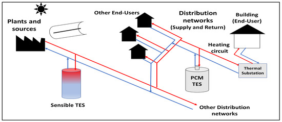
Figure 1.
Location of the thermal energy storage system in the building heating network.
Studies have shown reductions in central heating production by up to 14.8% through optimization of DH systems [14,15,16]. However, investigations into the dynamic behavior of DH networks’ latent storage systems remain limited [17]. These latent storage systems utilize phase change materials (PCMs) within tube and shell structures to store heat [18]. In this published work [17], the shell-and-tube TES system is used and only one PCM type (RT-70HC) is considered as storage medium. This TES is considered to power a DH substation in the Grenoble urban heating network during the peak-period demand of the day. In another recent work [19], a conventional water tank is used as a TES to provide the necessary thermal energy for an existing urban area in Loughborough, UK. It was found that using this type of TES (sensible) is advantageous in order to address the mismatch between heat generation and demand; however, due to its low energy storage density, the required TES volume in this DH system is high. To optimize the TES system, several numerical studies have aimed to evaluate the TES energy performance by employing cascade PCMs [20,21,22]. In these studies, three different PCMs are used to achieve a high volumetric storage capacity and high storage efficiency. These PCMs are either placed in spherical capsules or in shell-and-tube heat exchangers. Based on their results, they demonstrated that using cascade PCMs is advantageous and achieves better performance when compared to a single PCM system.
Efforts to enhance the thermal performance of latent storage systems have led researchers to focus on utilizing multiple PCMs [23,24,25]. Hassanpour et al. [24] proposed the integration of a cascade TES with geothermal resources for a DH system. The TES system is designed to supply the building’s energy consumption. In this study, fatty acids are used as PCMs with a melting temperature ranging between 31.5 °C and 63 °C. This shows that employing cascade PCMs is suitable for use with geothermal resources and can successfully provide the necessary thermal energy for heating buildings. Several studies suggest that employing multiple cascading stages of PCMs can significantly improve the performance of TES systems [26,27,28]. In [26], the performances of cascade PCMs placed in spherical capsules are investigated, and they demonstrated that using more than three stages does not add any appreciable improvement. Despite the mentioned advantages, only sensible and single PCM TES systems have generally been used in DH networks. For example, Xiang et al. [29] proposed the integration of a seasonal borehole TES for powering a DH system in Geneva city, Switzerland. The same TES has also been used by several researchers [30]. In addition to this type of TES, sensible water tanks TES by using is also one of the most used systems in DH networks [31]. As an example of these works, Yang et al. [32] studied the performance of a TES using water as storage medium in a DH system. Th authors showed that the TES contributes successfully to limiting the peak load and reduces the DH energy consumption. Based on the previous literature review, there is a dearth of research on the use of cascade PCM TES in DH networks, and few case studies have attempted to evaluate their comparative performances with conventional sensible and latent TES systems. Therefore, this study aims to identify the optimal TES configuration for DH systems by comparing three types of TES systems: sensible, latent, and cascade latent shell and tube storage systems. A fast-lumped thermal dynamic model is developed to simulate these systems’ operations; this is validated against experimental data. Through comprehensive comparative and parametric analyses, this research aims to guide decision making for implementing TES systems in DH applications, considering efficiency and adaptability to varying operating conditions.
2. System Description
A DH consists of a heat source, a network for distributing hot water to users, and a return network. Heat is transferred from the primary network to the secondary network via a sub-station for each user. Hot water is generally delivered to users at a temperature below 100 °C. Over the year, the production units of a DH run at only a quarter of their capacity. This means that peak consumption is four times higher than the average load. During a typical heating day, these peaks account for around 30% of the total thermal consumption. It is common for back-up generators to be polluting and expensive thermal power plants. The use of latent thermal storage system, which would store heat when demand is low and release it to the DH when demand is high, could address this problem. PCMs are employed in this sort of storage. A major benefit of this method is that the phase shift occurs at constant pressure and temperature, allowing for more energy storage per unit volume (and mass). Storage volumes are reduced as a result, lowering the cost of the system, and limiting heat losses that are proportionate to the tank’s external surface.
As a means of latent heat storage, tube and shell technology is frequently adopted (see Figure 2). The PCM fills the space left by the fluid that moves through the tubes to transfer heat. The functioning of all considered case studies, i.e., case 1, case 2 and case 3, can be described as follows: During the charging process, the hot heat transfer fluid heats up to a higher temperature than the storage medium (water or PCM). In this process, thermal energy is transferred from the working fluid to the storage medium which increases its temperature (thermal storage process). If water is used as storage medium (case 1), its temperature increases, and only sensible heat is stored. If one PCM or multiple PCMs are used as storage medium (case 2 and case 3), its physical phase is also changed from solid to liquid (melting process), and the heat is stored as sensible and latent forms. During the discharging process, the cold heat transfer fluid flows through the TES tank and the heat is then transferred from the storage medium to the working fluid and leads to the discharge of the TES. If water is used as a storage medium (case 1), its temperature is decreased during this process and only the sensible heat is released. If one PCM or multiple PCMs are used as storage medium (case 2 and case 3), the solidification process (liquid to solid phase change process) starts, and the TES releases the stored sensible and latent thermal energy.
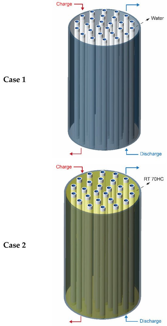
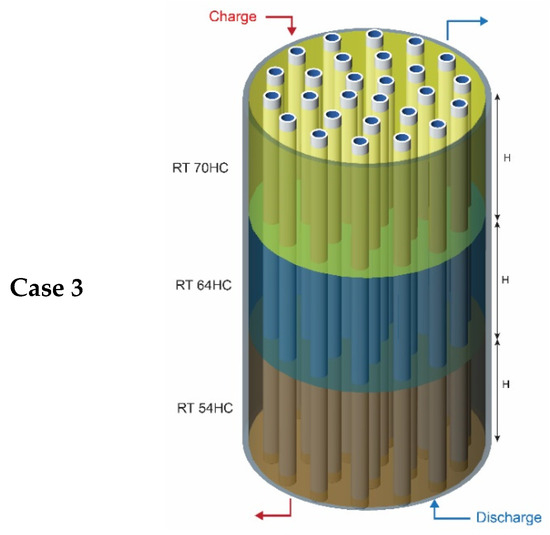
Figure 2.
The investigated thermal energy storage systems.
The main goal of using this kind of latent storage tank is to store a high amount of energy in a small space while making sure that charging and discharging takes only a few hours. For this TES, three configurations are investigated, namely the sensible water storage mode (case 1), latent storage mode (case 2), and cascade latent storage mode (case 3). The main objective is to define the suitable configuration for DH substations and to evaluate the influence of design and operations parameters on the system performances. The adopted TES volume is fixed at about 2 m3 with 400 vertical tubes. The used properties of each storage medium are summarized in Table 1.

Table 1.
Properties of the considered storage meduims [33].
3. Physical Modelling and Validation
The approach utilized in this study to model TES systems relies on the application of the first law of thermodynamics to each individual medium involved. This fundamental law links changes in internal energy within a given volume to the rate of thermal energy exchange. For the TES configurations under investigation, two distinct mediums are identified: the HTF medium and the storage medium, with the latter being either water for sensible storage units or PCMs for latent storage units. To capture the dynamic thermal behavior of the storage systems, the study employs transient energy balances and adopts the lumped-capacitance (LC) modeling approach. The LC approach is favored due to its simplicity and computational efficiency when compared to more intricate computational fluid dynamics (CFD) methods that involve solving multiple coupled partial differential equations (PDEs). In contrast, the LC approach entails solving ordinary differential equations (ODEs) for each domain (HTF and storage medium), resulting in significantly faster computations. The storage unit is discretized into several control volumes, each encompassing both the HTF and storage medium domains (as depicted in Figure 3). The entire system is assumed to be well-insulated, and uniform temperatures are considered within each domain of every control volume. Furthermore, owing to the staggered arrangement of tubes in the thermal storage system, a symmetry region surrounding each tube is considered, where heat transfer through conduction is neglected. As a result, studying a single storage unit is deemed sufficient to represent the overall behavior of the entire system. It is noteworthy that the assumption of a symmetrical system and the selection of the LC modeling approach have been verified through experimental validation by numerous researchers in the literature [23,34,35], specifically for shell-and-tube TES systems. This validation provides confidence in the appropriateness and accuracy of the chosen modeling method for the objectives of this study.
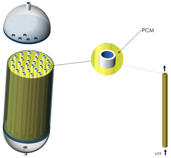
Figure 3.
The considered shell and tube TES.
By adopting the previous assumptions, the transient energy balance for each storage medium can be given as follows:
- For the HTF medium:
Control volume 1:
Control volume 2:
Control volume N:
where:
is the mass flow rate in one tube which is equal to the total mass flow rate divided by the total number of tubes in the storage system. A represents the heat transfer area that exists between the HTF and the storage media in each control volume. According to Gnielinski’s correlation, the convective heat transfer coefficient (hf) is calculated as follows [36,37]:
Dh is the hydraulic tube diameter and f is the friction coefficient.
To ensure a reliable operation of the system, the necessary thermal power by users must remain constant during the operation of the heating network. Consequently, a Proportional–Integral–Derivative (PID) system must be used to control the HTF mass flow rate. During the charging or discharging process of the storage system, The DHN substation regulates the water pump speed, i.e., the HTF mass flow rate, to achieve the appropriate thermal power (P suitable). The previous real functioning strategy is modeled and included in the dynamic model as follows:
Due to the fact that the capacity of commercial water pumps is capped by a maximum and a minimum flow rate, the variation in the HTF mass flow rate can be estimated using the following formula:
The suitable thermal power ranges from 40 kW to 70 kW; the maximum/minimum capacity of the water pump are taken from [17,23] and are equal to 0.86 kg/s and 0.2 kg/s, respectively. The energy consumption of the pump can also be estimated by using the Bell–Delaware method as follows:
where is the pump efficiency and the pressure drop is given by .
- For the storage medium (Sensible or latent):
By using the energy balance for the storage medium, the following system of equation is written as:
Control volume 1:
Control volume 2:
Control volume N:
Physical phase transition is simulated in the case of latent storage (PCM) by utilizing a temperature-dependent heat capacity of the PCM. When PCM is melting or solidifying, its heat capacity changes with temperature, allowing it to store more energy than a sensible storage medium whose heat capacity remains constant. The heat capacity of water (in the sensible storage case) is assumed to be 4.18 kJ/kg K in this study. On the other hand, the PCM heat capacity is computed as follows [38,39]:
where:
PCM liquid fraction is denoted by f(T), and the latent heat of fusion is denoted by Ls in [J/kg].
The baseline heat capacity of PCM can be calculated as follows:
is the heat capacity of solid PCM, and is the capacity in a liquid state.
The PCM liquid fraction is represented by the quantity f(T), and its value can range from 0 (for the solid state) to 1 at any given temperature (for the liquid state). The value of f(T) changes throughout the phase transition process, and this value can be expressed as a temperature-dependent function [39,40]:
By using Equation (15), the final form of the PCM heat capacity function can be given as:
For the purpose of simulating the transient heat transfer in PCM while the examined system is operating, the temperature-dependent function described above is incorporated into the energy equations (Equations (8)–(10)). This methodology, along with the PCM heat capacity function which was also utilized, has been tested and validated against experimental measurements such as those described in the literature [39,41,42]. Once the sensible storage case is considered, i.e., water tank, the previous heat balance equations are solved by substituting the temperature-dependent function with a constant value of heat capacity.
To assess the reliability of the previous described dynamic model, a real case study of a 180 kWh TES installed at Flaubert DH substation (France) [17] is considered. The same design and operation parameters from this study [17] are used as input parameters in the developed dynamic computational model and obtained numerical findings were compared with experimental data. In this experimental work a shell and tube TES system is considered and PCM RT-70HC is used as storage medium. The used PCM mass is equal to 1.68 tons and the HTF mass flow rate is regulated depending on the desired thermal power. The considered mass flow rate varies between 0.2 kg/s and 1.58 kg/s. It is interesting to note the considered 180 kWh TES designed to produce a constant thermal power with suitable water temperature during the peak load period in the DH substation. This constant thermal power is produced thanks to the mass flow regulation system. The same design and operation conditions are used as input parameters in the developed model; the obtained results are given in Figure 4. This figure shows the variation in the produced water temperature from the TES during the functioning of the DH system. It can be seen clearly that both the measured and the simulated produced water temperature from the TES tank follow the same dynamic behavior. The measured and predicted water temperature exhibits a maximum absolute error of 2.5 °C and a mean absolute error of 0.8 °C. Moreover, the maximum relative error for water temperature reaches 3.7%, while the mean relative error stands at 1.1%.
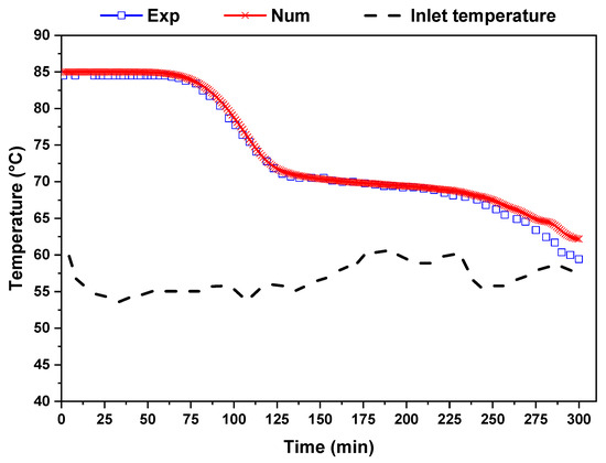
Figure 4.
Comparison between obtained numerical results and experimental data from [17].
4. Results and Discussion
In this section, we conduct a numerical investigation of the performances of the three studied TES systems, namely the sensible storage tank, latent storage tank, and cascade latent storage tank, specifically focusing on the charging process. To ensure a fair comparison, all cases involve the same volume for the shell and tube system, with only the type of storage medium being varied. The main criteria for comparing the performances of the TES systems are their ability to store and release a constant thermal power during the operation of the DH network, while maintaining a suitable temperature level. Additionally, a key consideration is to minimize the pumping energy consumption required for their functioning. By analyzing these parameters, we aim to determine which TES configuration demonstrates the best characteristics in terms of thermal energy storage and release efficiency, as well as their impact on the DH network’s overall performance. The investigation provides valuable insights into the capabilities and limitations of each TES system under consideration, aiding in the selection of the most suitable configuration for DH applications.
4.1. TES Functioning Analysis
This section presents and discusses the study of the TES systems’ functioning, in particular, how the cascade latent storage tank, sensible storage tank, and latent storage tank operate. Our main concern in this study is the charging procedure. The temperature change in the storage medium at three distinct shell and tube unit positions throughout the charging operation is shown in Figure 5. The behavior of the storage medium’s temperature is observed in the context of the sensible storage case study (shown in Figure 5a). The temperature of the storage medium rises from its starting point of 50 °C to begin the operation. The temperature rises throughout the process until it reaches the ultimate temperature of 85 °C, when it stabilizes. It is important to emphasize that the TES system charges from the top to the bottom section. This dynamic contributes to a rapid temperature increase in the storage medium situated at the top of the TES, relative to those positioned in the middle and at the bottom of the system. This distinct thermal distribution characteristic is of particular interest and sheds light on the intricacies of the charging mechanism within the sensible storage configuration. By closely examining Figure 5b, where the PCM RT 70HC is employed as the storage medium in place of water, a distinct behavior emerges. The temperature of the TES system displays a distinct pattern. Initially, the temperature ascends until it reaches the PCM’s melting point, situated at around 70 °C. At this juncture, the temperature remains steady, indicating the transition of heat storage in the latent form. Subsequent to this latent heat absorption phase, the TES temperature continues to rise until it ultimately stabilizes at the final temperature of 85 °C. This multifaceted thermal profile captures the progression of the TES system’s operation when utilizing PCM RT 70HC, offering valuable insights into the latent heat storage process within this specific configuration. Due to the sequential flow of the hot working fluid from the upper section to the lower section, a notable phenomenon is observed. The PCM situated near the upper region of the system experiences rapid heating. Consequently, it attains the final temperature of 85 °C before the PCM located in the middle and lower portions of the system. This trend is attributed to the sequential nature of the heating process, wherein the uppermost PCM encounters higher temperatures sooner, elucidating the nuanced thermal dynamics within the system. In the third case study, where a combination of multiple PCMs is employed as the storage medium within the TES system, the temperature variation in the storage medium is presented in Figure 5c. This observed temperature trend substantiates the authentic behavior of the cascade TES system. In this configuration, the storage medium’s temperature follows a distinct pattern. It progressively increases until it reaches the melting point of each PCM utilized within the system. For example, the PCM that is located close to the top part of the storage tank (RT 70HC) heats up quickly, reaching a temperature stability point of around 70 °C. In a similar manner, the PCM located in the center of the TES system (PCM RT 64HC) experiences heating before stabilizing at its assigned melting point, which is around 64 °C. In contrast to the other regions, the PCM RT 54HC used as the storage medium at the bottom of the TES system shows a slower rate of temperature rise. It then reaches stability at its unique melting point, which is around 54 °C. This complex temperature behavior illustrates the successive heating and stability of several PCMs within discrete system regions, capturing the intrinsic dynamics of the cascade TES system.
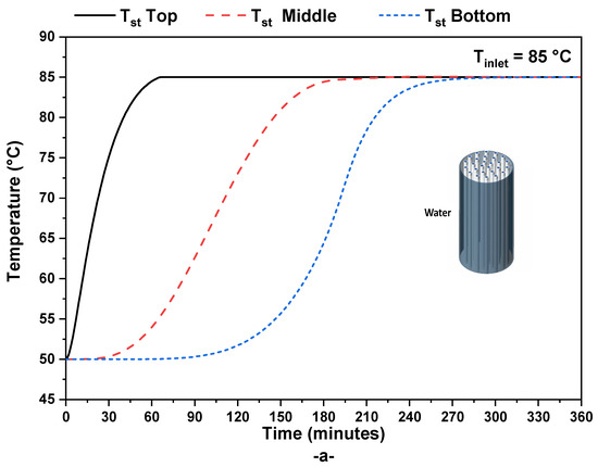
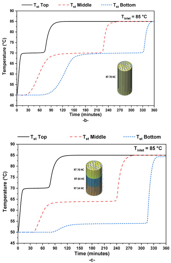
Figure 5.
Evolution of the storage medium temperature during the charging process: (a) sensible water tank, (b) RT 70HC Tank, and (c) cascade PCM tank.
To monitor the progression of the TES system’s charging process, a reliable indicator is utilized: the PCM liquid fraction. The variation in this indicator is illustrated for Case 2 (single PCM tank) and Case 3 (cascade PCM tank) in Figure 6. This physical parameter, namely the PCM liquid fraction, serves as a robust representation of the extent to which the PCM has melted within the TES system. Its values are indicative of the amount of PCM in the liquid state. Specifically, if the PCM liquid fraction is at zero, it signifies that the PCM tank is in a solid physical state, implying that the latent storage process has not yet commenced. Conversely, when this parameter attains a value of one, it signifies that the PCM tank has been completely charged, and the phase change process has been accomplished.
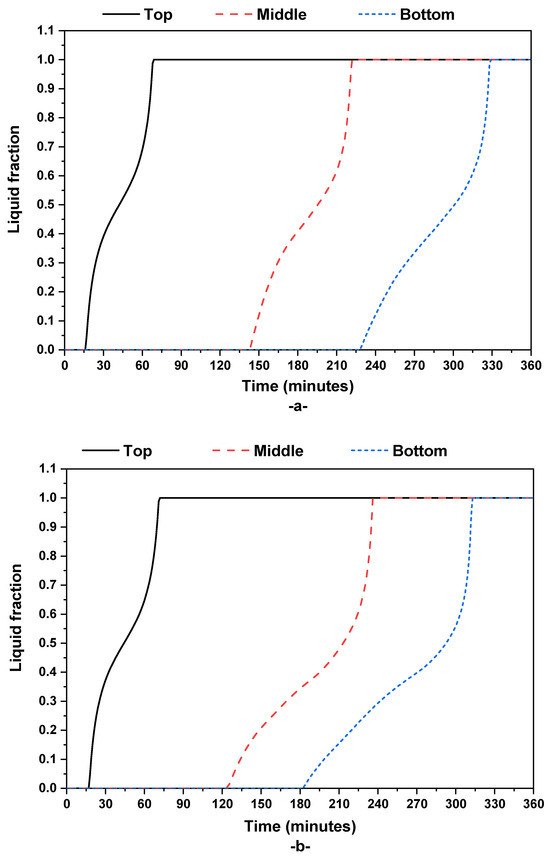
Figure 6.
Time-wise variation in the liquid fraction at different positions in the storage units: (a) RT 70HC PCM storage and (b) cascade PCMs storage.
The results presented in Figure 6 illuminate the charging dynamics of both Case 2 and Case 3. It is notable that both configurations achieve complete charging, where the PCM tanks transform from a solid to a fully melted state. Case 2 (See Figure 6a) achieves full charging after a duration of 330 min, whereas Case 3 (See Figure 6b), featuring the cascade PCM tank, achieves the same outcome in a slightly shorter timeframe of 310 min. These insights underscore the effectiveness and efficiency of both single PCM and cascade PCM tank configurations in facilitating the latent heat storage process.
4.2. Comparative Study
To perform a comparison investigation of the various TES systems’ performances, all three tanks are charged under the same operating circumstances. Figure 7a,b, respectively, show the working fluid’s temperature fluctuation at the top and bottom regions of the TES systems. There is a noticeable pattern that appears at the beginning of the charging process. There is a rapid drop in the HTF temperature at the top portion of the TES system (Figure 7a). The HTF temperature rapidly decreases from the starting TES temperature of 50 °C to the intake temperature of 85 °C, indicating this reduction. The significant quantity of heat transferred from the heated HTF to the top section of the TES system is responsible for this first decline. For the three case studies, distinct behaviors emerge as the storing process unfolds. The HTF temperature in the top area rises linearly in Case 1 (sensible storage) until it reaches the 85 °C inlet temperature. On the other hand, the HTF temperature in the top area stabilizes at around 80 °C for Case 2 (single PCM storage) and Case 3 (cascade PCM storage). The phase transition, or latent heat storage process, that takes place in this higher area is what causes this stability. The HTF temperature continues to rise once the phase shift in this area is finished, finally reaching the 85 °C inlet temperature.
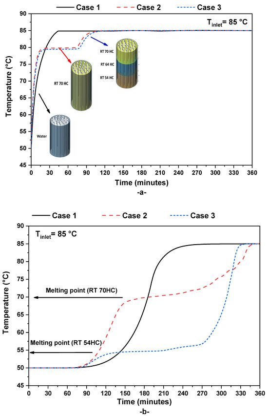
Figure 7.
Variation in HTF temperature at (a) the top of the storage unit and (b) at the bottom of the storage unit for the three case studies.
A distinctive behavior is observed at the bottom region of the TES system, depicted in Figure 7b. Notably, this behavior varies across the different case studies. In the context of the sensible case study, the HTF temperature at the TES outlet maintains a steady value of approximately 50° C. This constancy indicates that all the heat from the HTF has been successfully transferred to the storage medium as it traverses the tank from the top to the bottom. As the storage process advances, the HTF temperature at the bottom region experiences a linear increase until it matches the inlet temperature of 85 °C. This behavior is indicative of the culmination of the charging process, where the storage medium reaches the desired temperature of 85 °C, mirroring the HTF temperature at the end of the charging cycle.
In Case 2, where a single type of PCM is utilized (specifically RT 70HC) as the storage medium, a distinct pattern emerges in the behavior of the outlet HTF temperature. Initially, the HTF outlet temperature exhibits a gradual increase until it aligns with the transition point of the PCM, which is approximately 70 °C. During this phase, the HTF outlet temperature remains relatively stable, indicating that heat is being stored in the latent form within the PCM. Upon the successful completion of the latent heat storage process, the HTF outlet temperature commences a linear increase, reflective of the sensible heat storage process. This upward trend continues until it reaches the desired temperature of 85 °C.
In contrast, the cascade PCM storage configuration presents a unique behavior for the HTF outlet temperature. Here, the HTF outlet temperature stabilizes at around 54 °C, coinciding with the melting point of the PCM RT 54HC, which is positioned at the bottom of the TES system. This phase is characterized by the latent heat storage process, wherein the PCM undergoes melting and absorbs heat, maintaining the temperature stability. Subsequent to the complete melting of this PCM, the HTF outlet temperature follows a linear rise due to the sensible heat storage process. Eventually, this temperature ascends to the final temperature of 85 °C.
The cascade TES configuration attains full charging when all segments of the tank achieve the final temperature of 85 °C. This intricate interplay of latent and sensible heat storage mechanisms highlights the dynamic thermal behavior of the cascade TES system.
In DH networks, maintaining a stable thermal power output during peak-demand periods is crucial for ensuring the proper functioning of the system. Therefore, the ability to store a constant thermal power in the TES system over an extended duration is a key performance indicator. In Figure 8a, the instantaneous stored thermal power in three different TES systems is illustrated. It is worth noting that in all case studies, the target thermal power to be stored in the TES tank is fixed at 40 kW, and this level is achieved with the help of the regulating HTF pump, as described in Equations (5) and (6). The figure demonstrates that all three TES configurations are capable of storing a stable thermal power of 40 kW. However, the duration for which this constant thermal power can be stored varies among the different cases. In Case 1 (sensible storage), the duration of constant thermal power storage is relatively minimal. In contrast, in Case 3 (cascade PCM tank), which employs a combination of PCMs, the duration of constant thermal power storage is maximal. Specifically, using a single PCM tank (Case 2) increases the duration of constant thermal power storage by about 50%, and using a cascade PCM tank (Case 3) further enhances this duration by approximately 65% compared to the sensible TES case. This behavior can be attributed to the higher energy storage density of PCMs compared to sensible storage mediums such as water. The use of PCMs allows for a more efficient and prolonged storage of thermal energy. Moreover, employing a cascade TES system (Case 3) instead of a single PCM tank (Case 2) proves advantageous and further improves thermal storage performance. In summary, the results indicate that using PCMs, especially in a cascade configuration, significantly enhances the ability of a TES system to store a constant thermal power over an extended period, which is a critical factor for maintaining stability in DH networks during peak-demand periods.
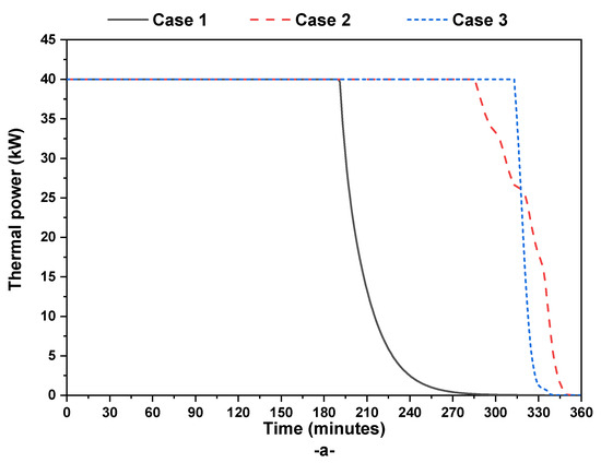
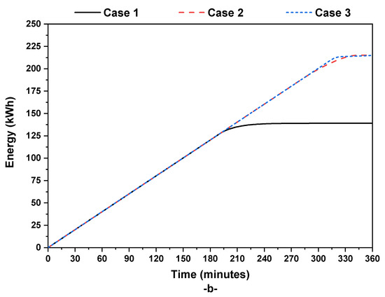
Figure 8.
Evolution of (a) instantaneous thermal power and (b) cumulated stored thermal energy in the three studied storage units.
As anticipated, the thermal energy storage capacity in Case 2 (single PCM tank) and Case 3 (cascade PCM tank) surpasses that of the conventional water tank storage, as shown in Figure 8b. The cumulative thermal energy stored in all three tanks exhibits a linear increase from the onset of the storage operation until it reaches its maximum value. In specific terms, for Case 1 (sensible water tank), the cumulative stored thermal energy reaches approximately 139 kWh. However, for both Case 2 and Case 3 (which employ PCM tanks), the cumulative stored thermal energy increases to around 215 kWh. This outcome affirms the superiority of PCM-based tanks for heating networks, as their energy storage capacity exceeds that of sensible water tanks by approximately 55%. This result underscores the advantages of utilizing PCM tanks in DH systems, where the higher energy storage capacity is advantageous for meeting the thermal demands of the network efficiently, especially during peak-demand periods.
The impact of the TES tank type on pumping energy consumption is evaluated through the variation in the used mass flow rate (Figure 9a) and the cumulative consumed energy by the pump system (Figure 9b). Notably, the water pump used in this context employs a regulation Proportional–Integral–Derivative (PID) system to control valve openings, thereby regulating the water flow rate within the tank based on the desired thermal power at the TES outlet. The influence of this PID regulation system is clearly reflected in Figure 8a, where the water flow rate exhibits distinct patterns for each TES type.
Figure 9.
Evolution of (a) instantaneous HTF mass flow rate and (b) consumed pumping energy in the three studied storage units.
In Case 1 (sensible TES tank), the flow rate remains minimal at the outset of the storage process as the desired thermal power is reached during this initial period. However, when the desired thermal power decreases (as observed in Figure 7a), the PID system rapidly increases the mass flow rate until it reaches the pump’s maximum capacity. This rapid increase is implemented to attain the fixed thermal power target within the TES tank.
In contrast, when PCM tanks are employed, the mass flow rate initially drops and eventually stabilizes at a plateau. During this phase, the phase change process occurs inside the tank at approximately constant temperature, resulting in a stable mass flow rate utilization. After the completion of the phase change phenomena, the mass flow rate increases until reaching the pump’s maximum capacity. Analyzing the mass flow rate utilization in Case 3 (cascade PCM tank), it can be observed that the mass flow rate remains minimal for an extended period compared to both Case 1 and Case 2. This behavior is attributed to the utilization of multiple PCMs with different melting points, ensuring a prolonged period of constant thermal power storage. Towards the end of the charging process, the mass flow rate drops and stabilizes at its maximal value.
To quantify the pumping energy consumption in each case study, the cumulative energy consumption is presented in Figure 9b. These results highlight the advantage of employing multiple PCMs in the TES tank (Case 3) over using a single PCM tank (Case 2) or a sensible water tank (Case 1). Specifically, minimal pumping energy consumption is achieved in Case 3, whereas both Case 2 and Case 1 exhibit higher and roughly similar energy consumption levels. The use of a cascade PCM tank reduces pumping energy consumption by approximately 30% when compared to both single PCM tank and water tank systems. These findings emphasize the efficiency and energy-saving benefits of employing cascade PCM tanks in TES systems, particularly for DH applications where minimizing pumping energy consumption is crucial.
4.3. Parametric Study
A thorough parametric study is carried out in an effort to improve the effectiveness and flexibility of TES systems for DH applications. The goal of this research is to provide clarity regarding the complex interactions between many factors and the TES system’s performance, with a particular focus on Case 3, which uses a cascade PCM tank arrangement. This parametric investigation’s primary goal is to analyze the impact of each PCM’s quantity used in the same TES volume. Comprehending this dependence is essential for customizing TES systems to satisfy the ever-changing requirements of DH networks while maximizing energy efficiency. By providing the foundation for wise design and operational choices, this parametric research makes it easier to create future heating systems that are more durable and energy-efficient. This section explores several PCM combinations in the cascading TES tank. The primary focus is to evaluate how these combinations impact both the HTF outlet temperature and the duration of constant thermal power storage. Four distinct cascade combinations come under scrutiny:
- (a)
- 33% PCM RT70, 33% PCM RT64, 33% PCM RT54
- (b)
- 80% PCM RT70, 10% PCM RT64, 10% PCM RT54
- (c)
- 10% PCM RT70, 80% PCM RT64, 10% PCM RT54
- (d)
- 10% PCM RT70, 10% PCM RT64, 80% PCM RT54
The aim of this investigation is twofold. Firstly, it seeks to understand how varying the quantity of each PCM within the TES tank influences the system’s performance. Secondly, it aims to identify the optimal combination of PCMs for the studied shell-and-tube cascade TES system.
Figure 10a illustrates the time-dependent evolution of the HTF outlet temperature from the cascade PCM tank for all the studied cases. It is evident that the outlet HTF temperature is significantly influenced by the specific combination of PCMs adopted. The maximal outlet temperature is observed in case (b), while the minimal outlet temperature is reached in case (d). The HTF outlet temperature is closely tied to the predominant PCM used in the tank. For instance, in case (b), where 80% of the tank is filled with PCM RT70, the HTF outlet temperature is maximized and closely approaches the melting point of this particular PCM. Conversely, in case (d), where PCM RT54 with a melting point of around 54 °C is utilized in 80% of the tank, the resulting HTF temperature is minimized and near the melting point of this PCM. This analysis sheds light on the dynamic interplay between PCM composition and thermal performance within the cascade TES system, offering insights that can guide the selection of optimal PCM combinations for specific heating network requirements.
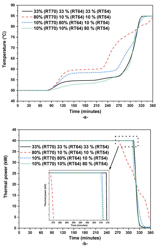
Figure 10.
Evolution of (a) outlet HTF temperature from the cascade storage unit and (b) the instantaneous stored thermal power.
Through an analysis of Figure 10b, which presents the instantaneous stored thermal power for each cascade Phase PCM, it becomes evident that the maximal duration of constant thermal power storage is observed in case (a), whereas the minimal duration is obtained in case (b). This observation underscores that utilizing the cascade TES configuration with 80% PCM RT70, 10% PCM RT64, and 10% PCM RT54 is not advisable, as it reduces the duration of constant thermal power production. To specify, the duration of constant thermal power production is equal to 315 min for case (a), 274 min for case (b), 312 min for case (c), and 310 min for case (d). In the context of DH networks, both achieving maximal hot transfer fluid (HTF) outlet temperature and a longer duration of constant thermal power production are critical requirements. As a result, the recommended cascade TES configuration in this study is case (c), where both of these essential conditions are satisfied. This choice ensures that the heating network can benefit from both a prolonged period of stable thermal power production and the highest attainable HTF outlet temperature, optimizing the system’s overall performance for DH applications.
The analysis of the influence of the selected cascade PCM configuration on pumping energy consumption is presented in Figure 11. The instantaneous HTF mass flow rate and the cumulative energy consumed by the pump system are showcased.
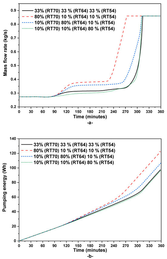
Figure 11.
Variation in (a) the HTF mass flow rate during the charging process and (b) the cumulated pump energy consumption.
This analysis reaffirms the earlier observation that cascade TES case (b) is not recommended from the perspective of pumping energy consumption. Notably, case (b) exhibits the highest mass flow rate utilization, while both case (a) and case (c) achieve minimal mass flow rate utilization. In terms of total pumping energy consumption, case (b) is less efficient, consuming significantly more energy compared to the other configurations. Conversely, case (c) results in a 12% reduction, case (a) in a 20% reduction, and case (d) in a 21% reduction in pumping energy consumption compared to case (b).
These findings underscore the importance of carefully selecting the cascade PCM configuration in a TES system not only to optimize thermal performance but also to minimize energy consumption, particularly in DH applications where energy efficiency is a key consideration. Case (a) and case (c) emerge as the recommended choices, as they strike a favorable balance between stable thermal power production, HTF outlet temperature, and energy-efficient operation.
5. Conclusions
In this study, three different thermal energy storage (TES) systems for the collective heating of buildings were thoroughly explored. A simplified lumped dynamic model for TES systems was firstly developed and then validated with experimental data from the literature. The comparison between sensible, latent, and cascade latent shell and tube storage configurations was carried out under different design and operation conditions, and the main findings can be summarized as follows:
- In comparison to sensible systems, the latent and cascade latent TES showed greater thermal energy storage capabilities, underscoring their potential for effective DH networks.
- Using a single PCM tank increases the duration of constant thermal power storage by about 50% compared to the sensible TES.
- Using a cascade PCM tank further enhances the TES performance and increases this duration of constant thermal power production by approximately 65% compared to the sensible TES case.
- The distribution of PCM within cascade TES proved pivotal in influencing system performance. It is demonstrated that the optimal cascade configuration—10% PCM RT70, 80% PCM RT64, 10% PCM RT54—showcased prolonged stable thermal power production and reduced pump energy consumption.
- The use of a cascade PCM enhances the tank energy efficiency and reduces pumping energy consumption by approximately 30% when compared to both single PCM tanks and sensible water tank systems.
These findings underscore the critical role of PCM selection in achieving prolonged thermal power and improved energy efficiency in DH systems. Overall, this study’s insights provide valuable guidance for practitioners and designers seeking efficient TES configurations tailored for DH applications. The emphasis on PCM distribution offers a pathway towards optimizing TES efficiency and enhancing the performance of DH networks. As a perspective of the present work, this optimal cascade PCM tank will be coupled with solar thermal collectors and investigated during both charging and discharging operations for achieving the goal of green DH networks.
Author Contributions
Conceptualization, B.L. and E.A.; methodology, A.A.; software, B.L.; validation, A.A. and B.L.; formal analysis, A.A.; investigation, B.L.; resources, E.A.; writing—original draft preparation, B.L.; writing—review and editing, E.A.; visualization, A.A.; project administration, E.A.; funding acquisition, E.A. All authors have read and agreed to the published version of the manuscript.
Funding
This research was funded by the Agency for Research & Innovation in the Ministry of Education in Saudi Arabia grant number [IFKSUDR_E129] and the APC was funded by the same agency.
Data Availability Statement
Data are contained within the article.
Acknowledgments
The authors extend their appreciation to the Agency for Research & Innovation in the Ministry of Education in Saudi Arabia for funding this research work through the project number (IFKSUDR_E129).
Conflicts of Interest
The authors declare no conflicts of interest.
References
- European Commission. In Focus: Energy Efficiency in Buildings; European Commission: Brussels, Belgium, 2023.
- Ju, Y.; Hiltunen, P.; Jokisalo, J.; Kosonen, R.; Syri, S. Benefits through Space Heating and Thermal Storage with Demand Response Control for a District-Heated Office Building. Buildings 2023, 13, 2670. [Google Scholar] [CrossRef]
- IAE. Tracking Clean Energy Progress 2023; IAE: Paris, France, 2023. [Google Scholar]
- IAE District-Heating. Available online: https://www.iea.org/reports/district-heating (accessed on 20 November 2023).
- Lyu, Y.; Pan, Y.; Huang, Z. Development and Test of a New Fast Estimate Tool for Cooling and Heating Load Prediction of District Energy Systems at Planning Stage. Buildings 2022, 12, 1671. [Google Scholar] [CrossRef]
- Lebrouhi, B.E.; Schall, E.; Lamrani, B.; Chaibi, Y.; Kousksou, T. Energy Transition in France. Sustainability 2022, 14, 5818. [Google Scholar] [CrossRef]
- Lund, H.; Werner, S.; Wiltshire, R.; Svendsen, S.; Thorsen, J.E.; Hvelplund, F.; Mathiesen, B.V. 4th Generation District Heating (4GDH). Integrating Smart Thermal Grids into Future Sustainable Energy Systems. Energy 2014, 68, 1–11. [Google Scholar] [CrossRef]
- Averfalk, H.; Werner, S. Economic Benefits of Fourth Generation District Heating. Energy 2020, 193, 116727. [Google Scholar] [CrossRef]
- Ajbar, A.; Lamrani, B.; Ali, E. Dynamic Investigation of a Coupled Parabolic Trough Collector—Phase Change Material Tank for Solar Cooling. Energies 2023, 16, 4235. [Google Scholar] [CrossRef]
- Siddiqui, S.; Macadam, J.; Barrett, M. The Operation of District Heating with Heat Pumps and Thermal Energy Storage in a Zero-Emission Scenario. Energy Rep. 2021, 7, 176–183. [Google Scholar] [CrossRef]
- Narula, K.; de Oliveira Filho, F.; Villasmil, W.; Patel, M.K. Simulation Method for Assessing Hourly Energy Flows in District Heating System with Seasonal Thermal Energy Storage. Renew. Energy 2020, 151, 1250–1268. [Google Scholar] [CrossRef]
- Wang, J.; Evans, M.; Belusko, M.; Zhao, C.; Liu, M.; Bruno, F. Subcooling Effect on the Optimal Performance for a Transcritical CO2 Heat Pump with Cold Thermal Energy Storage. Heat Mass Transf. 2023, 59, 1257–1275. [Google Scholar] [CrossRef]
- Eynard, J.; Grieu, S.; Polit, M. Predictive Control and Thermal Energy Storage for Optimizing a Multi-Energy District Boiler. J. Process. Control. 2012, 22, 1246–1255. [Google Scholar] [CrossRef][Green Version]
- Shah, S.K.; Aye, L.; Rismanchi, B. Seasonal Thermal Energy Storage System for Cold Climate Zones: A Review of Recent Developments. Renew. Sustain. Energy Rev. 2018, 97, 38–49. [Google Scholar] [CrossRef]
- Ali, E.; Ajbar, A.; Lamrani, B. Modeling and Dynamic Simulation of a Phase-Change Material Tank for Powering Chiller Generators in District Cooling Networks. Sustainability 2023, 15, 10332. [Google Scholar] [CrossRef]
- Turski, M.; Sekret, R. Buildings and a District Heating Network as Thermal Energy Storages in the District Heating System. Energy Build. 2018, 179, 49–56. [Google Scholar] [CrossRef]
- Bentivoglio, F.; Rouge, S.; Soriano, O.; Tempass de Sousa, A. Design and Operation of a 180 KWh PCM Heat Storage at the Flaubert Substation of the Grenoble Urban Heating Network. Appl. Therm. Eng. 2021, 185, 116402. [Google Scholar] [CrossRef]
- Griffiths, P.; Hewitt, G. Heat Exchanger Design Handbook; Begell House: New York, NY, USA, 1990. [Google Scholar]
- Pans, M.A.; Claudio, G.; Eames, P.C. Theoretical Cost and Energy Optimisation of a 4th Generation Net-Zero District Heating System with Different Thermal Energy Storage Technologies. Sustain. Cities Soc. 2024, 100, 105064. [Google Scholar] [CrossRef]
- Mao, Q.; Zhang, Y. Thermal Energy Storage Performance of a Three-PCM Cascade Tank in a High-Temperature Packed Bed System. Renew. Energy 2020, 152, 110–119. [Google Scholar] [CrossRef]
- Wu, M.; Xu, C.; He, Y. Cyclic Behaviors of the Molten-Salt Packed-Bed Thermal Storage System Filled with Cascaded Phase Change Material Capsules. Appl. Therm. Eng. 2016, 93, 1061–1073. [Google Scholar] [CrossRef]
- Khor, J.O.; Sze, J.Y.; Li, Y.; Romagnoli, A. Overcharging of a Cascaded Packed Bed Thermal Energy Storage: Effects and Solutions. Renew. Sustain. Energy Rev. 2020, 117, 109421. [Google Scholar] [CrossRef]
- Lamrani, B.; Kousksou, T. Numerical Investigation of a Shell-and-Tube Latent Heat Thermal Energy Storage System for Urban Heating Network. J. Energy Storage 2021, 43, 103216. [Google Scholar] [CrossRef]
- Hassanpour, A.; Borji, M.; Ziapour, B.M.; Kazemi, A. Performance Analysis of a Cascade PCM Heat Exchanger and Two-Phase Closed Thermosiphon: A Case Study of Geothermal District Heating System. Sustain. Energy Technol. Assess. 2020, 40, 100755. [Google Scholar] [CrossRef]
- Nekoonam, S.; Ghasempour, R. Modeling and Optimization of a Thermal Energy Storage Unit with Cascaded PCM Capsules in Connection to a Solar Collector. Sustain. Energy Technol. Assess. 2022, 52, 102197. [Google Scholar] [CrossRef]
- Aldoss, T.K.; Rahman, M.M. Comparison between the Single-PCM and Multi-PCM Thermal Energy Storage Design. Energy Convers. Manag. 2014, 83, 79–87. [Google Scholar] [CrossRef]
- Elfeky, K.E.; Ahmed, N.; Wang, Q. Numerical Comparison between Single PCM and Multi-Stage PCM Based High Temperature Thermal Energy Storage for CSP Tower Plants. Appl. Therm. Eng. 2018, 139, 609–622. [Google Scholar] [CrossRef]
- Shen, Y.; Mazhar, A.R.; Liu, S. Comprehensive Review on Cascaded Latent Heat Storage Technology: Recent Advances and Challenges. J. Energy Storage 2022, 55, 105713. [Google Scholar] [CrossRef]
- Li, X.; Yilmaz, S.; Patel, M.K.; Chambers, J. Techno-Economic Analysis of Fifth-Generation District Heating and Cooling Combined with Seasonal Borehole Thermal Energy Storage. Energy 2023, 285, 129382. [Google Scholar] [CrossRef]
- Sadeghi, H.; Jalali, R.; Singh, R.M. A Review of Borehole Thermal Energy Storage and Its Integration into District Heating Systems. Renew. Sustain. Energy Rev. 2024, 192, 114236. [Google Scholar] [CrossRef]
- Jebamalai, J.M.; Marlein, K.; Laverge, J. Influence of Centralized and Distributed Thermal Energy Storage on District Heating Network Design. Energy 2020, 202, 117689. [Google Scholar] [CrossRef]
- Yang, X.; Svendsen, S. Improving the District Heating Operation by Innovative Layout and Control Strategy of the Hot Water Storage Tank. Energy Build. 2020, 224, 110273. [Google Scholar] [CrossRef]
- Rubitherm. Available online: http://www.rubitherm.eu (accessed on 1 April 2022).
- Mostafavi, S.S.; Taylor, R.A.; Saberi, P.; Diarce, G. Design and Feasibility of High Temperature Shell and Tube Latent Heat Thermal Energy Storage System for Solar Thermal Power Plants. Renew. Energy 2016, 96, 120–136. [Google Scholar] [CrossRef]
- Elbahjaoui, R.; El Qarnia, H. Thermal Performance of a Solar Latent Heat Storage Unit Using Rectangular Slabs of Phase Change Material for Domestic Water Heating Purposes. Energy Build. 2019, 182, 111–130. [Google Scholar] [CrossRef]
- Lamrani, B.; Khouya, A.; Zeghmati, B.; Draoui, A. Mathematical Modeling and Numerical Simulation of a Parabolic Trough Collector: A Case Study in Thermal Engineering. Therm. Sci. Eng. Prog. 2018, 8, 47–54. [Google Scholar] [CrossRef]
- Gnielinski, V. On Heat Transfer in Tubes. Int. J. Heat Mass Transf. 2013, 63, 134–140. [Google Scholar] [CrossRef]
- Medved, I.; Trník, A.; Vozár, L. Modeling of Heat Capacity Peaks and Enthalpy Jumps of Phase-Change Materials Used for Thermal Energy Storage. Int. J. Heat Mass Transf. 2017, 107, 123–132. [Google Scholar] [CrossRef]
- Halimov, A.; Lauster, M.; Müller, D. Validation and Integration of a Latent Heat Storage Model into Building Envelopes of a High-Order Building Model for Modelica Library AixLib. Energy Build. 2019, 202, 109336. [Google Scholar] [CrossRef]
- Feustel, H. Simplified Numerical Description of Latent Storage Characteris—Tics for Phase Change Wallboard; Lawrence Berkeley National Lab. (LBNL): Berkeley, CA, USA, 1995.
- Lamrani, B.; Lebrouhi, B.E.; Khattari, Y.; Kousksou, T. A Simplified Thermal Model for a Lithium-Ion Battery Pack with Phase Change Material Thermal Management System. J. Energy Storage 2021, 44, 103377. [Google Scholar] [CrossRef]
- El Ouali, A.; Khattari, Y.; Lamrani, B.; El Rhafiki, T.; Zeraouli, Y.; Kousksou, T. Apparent Heat Capacity Method to Describe the Thermal Performances of a Latent Thermal Storage System during Discharge Period. J. Energy Storage 2022, 52, 104960. [Google Scholar] [CrossRef]


Disclaimer/Publisher’s Note: The statements, opinions and data contained in all publications are solely those of the individual author(s) and contributor(s) and not of MDPI and/or the editor(s). MDPI and/or the editor(s) disclaim responsibility for any injury to people or property resulting from any ideas, methods, instructions or products referred to in the content. |
© 2024 by the authors. Licensee MDPI, Basel, Switzerland. This article is an open access article distributed under the terms and conditions of the Creative Commons Attribution (CC BY) license (https://creativecommons.org/licenses/by/4.0/).