Article

Nonlinear Performance of Steel Tube Tower in Ultra-High Voltage Transmission Lines under Wind Loads

School of Civil Engineering, Xi’an University of Architecture & Technology, Xi’an 710065, China
*
Author to whom correspondence should be addressed.
Buildings 2024, 14(1), 140; https://doi.org/10.3390/buildings14010140
Submission received: 29 November 2023 / Revised: 23 December 2023 / Accepted: 4 January 2024 / Published: 5 January 2024
(This article belongs to the Special Issue Earthquake Resistant and Vibration Control of Concrete Structures)

Abstract

:
As complex, statically indeterminate structures, transmission towers are subject to complex forces and are usually simplified into truss structures that only consider the effects of axial force. When the load and deformation of a tower are small, it is reasonable to carry out analysis according to the linear elasticity theory. However, the height of an ultra-high voltage (UHV) transmission tower is significantly large, meaning that the calculation result according to the current elastic analysis method often has a large deviation from the actual stress of the structure. With the influence of the bending moment at the end of the member, a numerical model is established considering the influence of geometric nonlinearity and material nonlinearity in this paper. The stress distribution characteristics and development law of UHV transmission towers in linear and nonlinear stress states are analyzed and studied. The real tower test and elastoplastic ultimate bearing capacity analysis show that the elastoplastic analysis is closer to the actual tower. The UHV steel pipe tower designed according to the linear elasticity and small deformation theory has a large safety margin under the design load, resulting in a significant waste of materials. Under the action of heavy load, the tower exhibits strong nonlinearity, and the influence of geometric and material nonlinear factors should be fully considered when designing the structural components in UHV transmission towers.

1. Introduction

Transmission towers, as statically indeterminate structures, sustain complex stress states. The analysis and design of transmission towers comply with the following assumptions: (1) transmission towers are simplified as a kind of spatial truss structure, i.e., structural members are treated as rods and the connections between the members are considered as hinged; (2) the deformation of the tower is in a small deformation range; (3) under different working states, every member is in linear elastic deformation, that is, the structural analysis is in accordance with linear elastic theory. In the case of a small load and deformation of the tower, it is reasonable to analyze this according to the linear elastic theory for tower structures. However, for a specially designed tower, like an ultra-high-voltage (UHV) transmission tower, its tall height and the significant vertical load require the plastic analysis method, meaning that the calculation results often deviate greatly from the actual force states of the structure if using linear elastic theory [1,2]. The above statements are mainly manifested in the following aspects. Firstly, the joints of the space truss model are hinged, while the joints in steel pipe towers that are widely used in UHV transmission lines are mostly connected by plug-in plates or flanges, which cannot be treated as pinned. The truss rod is subjected to a great embedding effect at structural joints, which generates a large bending moment. The resulting bending moment, named the secondary moment, has a second-order effect, and the corresponding stresses are called secondary stresses, which may bias the design of steel tube towers towards an unsafe design if the effects of secondary stresses on the transmission tower structure are not considered. Secondly, the ratio of span to height in UHV steel tube towers is large, and large deformations will cause changes in the stress conditions of the structure when applying high loads. Thirdly, as a highly elevated, statically indeterminate structure, the tower structure has mutual constraints and influences among the structural members when the actual force is applied. The yielding of some members does not destroy the entire structure, as the structure will be completely destroyed only when the number and position of the structural members yield to a certain extent. Steel material shall be wasted per the current design method that keeps all structural members in the elastic range. Therefore, the force analysis of the tower structure should not only take the material and geometric nonlinearity of the tower structure, but also the effect of secondary bending moments into account [3].
Domestic and foreign scholars have used finite element analysis (FEA) to perform nonlinear analyses of angle towers considering dual nonlinearity, but almost all research has focused on bearing capacity and failure mode analysis without focusing on the effects and distribution characteristics of secondary stresses [4,5,6,7,8,9]. Li et al. [1] studied the regulation of secondary stress distribution in UHV steel tube tower and its influencing factors through FEA, but the stress values were obtained according to the finite element model of the ideal beam–rod element, and the stresses obtained by theoretical calculations were not accurate enough. The research group of Sun Qing [10,11,12,13,14,15] examined the axial and seismic performance of high-strength circular concrete-filled thin-walled steel tubular columns. Their test results show that using high-strength Q690 steel could significantly contribute to a larger elastoplastic deformation capacity and delay the onset of post-peak behavior, even though a lower ductility capacity was provided. Wen et al. [16] analyzed the seismic reaction of a substation with explicit consideration of the dynamic interaction between the main plant and the EE mounted inside. Shuai et al. [17] studied the influence of the angle between the oblique material and the main material on the secondary stress of the UHV steel pipe tower. Han et al. [18] obtained the relationship curve between the secondary stress and the slenderness ratio by analyzing and fitting the UHV steel pipe tower. In addition, static nonlinear buckling analysis and dynamic analysis are employed to assess the ultimate load capacity and the most vulnerable parts of the tower [19]; static analysis shows that the leg members buckled, while dynamic analysis reveals that it is the diagonal members that buckle. Recent analyses indicate that a machine learning approach based on a convolutional neural network (CNN), used to predict the time history response of a transmission tower during the complex wind input, can provide highly accurate results [20]. Roy et al. [21] reviewed the structural modeling and the optimized design of transmission towers under wind loading, the wind causes stress among a large number of structural components, which makes analyses of the tower less accurate. For the calculation of secondary stress, the nonlinearity of the calculation model of the above scholars is not clear enough, and there is not much research on the secondary stress of the iron tower in the nonlinear state.
Currently, most research relies on lab tests on reduced-scale structural models, with very few data present from the full-scale model due to the super-high limit and excessive monetary expenditure of ultra-high voltage transmission towers. To provide a great deal of real data to solve such issues, a real tower with a total height of 101.7 m was tested under different direction wind inputs. A further refined finite element model was established to obtain the detailed variation tendency of stress and displacement on such structures. Considering the influence of the bending moment of the rod end, the finite element models that can be used include a beam–rod hybrid model and a rigid frame model. The beam–rod hybrid model uses beam elements for the main members of the tower body, cross-arm main material, cross-inclined material, and cross-differential members; the remaining members use bar elements; and all members of the rigid frame model are beam elements. The existing research results show that the calculation results of the beam–rod hybrid model are close to the experimental results [22]. Based on the finite element analysis software ANSYS 12.0, this paper adopts a beam–rod hybrid model that considers the dual effects of geometric nonlinearity and material nonlinearity. In addition, the distribution characteristics and development laws of the elastoplastic ultimate bearing capacity and secondary stress of the iron tower in linear and nonlinear states are carried out. This paper aims to provide more data support on the proper design of ultra-high voltage transmission lines under wind loads.

2. Establishment and Validation of FE Model

The SZ322P steel tube tower in the 1000 kV Huainan–Shanghai (Anhui Electricity East Transmission) Power Transmission Project is the research object in this paper, and is composed of steel tubes and angles. The tower legs and tower body are made of Q345 (nominal yield strength = 345 MPa) steel tube, and the diagonal member and accessory member are made of Q235 (nominal yield strength = 235 MPa) steel tube or angle. The total height for the tower is 110.7 m. The cross-sectional size for different structural members is summarized in Table 1. Design conditions for SZ322P are as follows: (a) eight LGJ-630/45 aluminum conductor steel reinforced (ACSR) cables are used for conductors and JLB240 Al-clad steel stranded wire is employed for ground wires. (b) The basic wind speed of 32 m/s and an ice-covering thickness of 10 mm are considered. Finally, (c) The horizontal gear distance is 480 m and the vertical gear distance is 600 m.

2.1. Establishment of FE Model

In this paper, the beam element of the finite element model of the tower adopts Beam189; the rod element adopts Link8; the yield strength of the Q345 and Q235 steel used is 345 MPa and 235 MPa, respectively; and the elastic modulus and Poisson’s ratio are 2.06 × 10⁵ MPa and 0.3, respectively. As the accessory members, gusset plates, bolts, etc., which are not directly stressed in the tower, generally use a large proportion of steel, this part of the mass is considered according to the mass increase factor in the force analysis. According to the statistics of construction drawings, the mass increase coefficient of SZ322P is 1.47, which is achieved by magnifying the steel density (7850 kg/m3) by 1.47 times. The material constitutive adopts an ideal elastoplastic model. The load of the tower includes the weight of the tower, the weight of the ground conductor, the tower body, and the wind load of the ground conductor, which are calculated following the “Technical Regulations for the Design of Overhead Transmission Line Tower Structure” [23]. Finally, the load is applied to the corresponding joint, and the loading adopts a gradual incremental loading method. The horizontal loading includes 90-degree wind actions and 60-degree wind actions. For the ultimate bearing capacity analysis, the design load is magnified by a certain multiple, the load in the gravity direction of all loading points remains unchanged. The load in the horizontal direction increases in linear proportions until the overall stiffness matrix of the structure is singular and the iteration fails to converge. The convergence of the program determines whether the ultimate bearing capacity of the tower is reached, i.e., the final bearing capacity is a multiple of the design load. The boundary conditions at the bottom of the tower are considered fixed. For geometric nonlinearity and material nonlinearity, ANSYS uses the U.L. format to achieve the coupling of dual nonlinearities. In this paper, the Newton–Raphson balance iteration method is used to solve the nonlinear incremental balance equations.

2.2. Comparison between FEM and Experiments

The SZ322P linear tower is used as it is the first UHV dual-circuit AC transmission and transformation project in China. This line has the characteristics of large transmission capacity and large load. The entire towers are made of steel pipe components. The large-scale use of steel pipe structures in China represents the first time that a variety of new connection technologies have been adopted, so it is necessary to carry out a true model test on the real tower. The test load is 100% of the design load. Figure 1 is a photo of the tower assembled at the test site. Figure 2 is the layout of the total station theodolite installed inside the tower to observe the displacement and deformation of the entire tower, where OP represents the observation point.
The comparison of displacement under 90-degree and 60-degree wind conditions between the test and FEA calculation is listed in Table 2. Figure 3 is the FE displacement cloud diagram corresponding to the design load. It can be seen that the lateral displacement of the tower top is the largest, and that the overall deformation is the same as the actual situation. Choosing test data of OP1, OP2, OP3, OP4, and OP10 to compare with finite element results, as shown in Figure 4. It can be seen that displacements of OP1, OP2, and OP10 are roughly consistent with the finite element displacement cloud diagram, and that the displacement variation trend and value at the other two observation points are close. The maximum displacement at the top of the steel tower in tests is 1.237 m, and the corresponding maximum displacement in FEM is 1.146 m. At the same time, Figure 4 shows that the tower is in a state of linear elastic deformation under the design load. In addition, the Mises stress contour at the bottom point of the tower (elevation = 2.4 m) and the mid-point (elevation of 16.4 m) are shown in Figure 5a,b, respectively. All of the structural members are in the elastic state. Through comparison and analysis, the finite element model is relatively rigid, and the calculation results are consistent with the overall change trend of experimental data, which validates the constructed model in this paper.

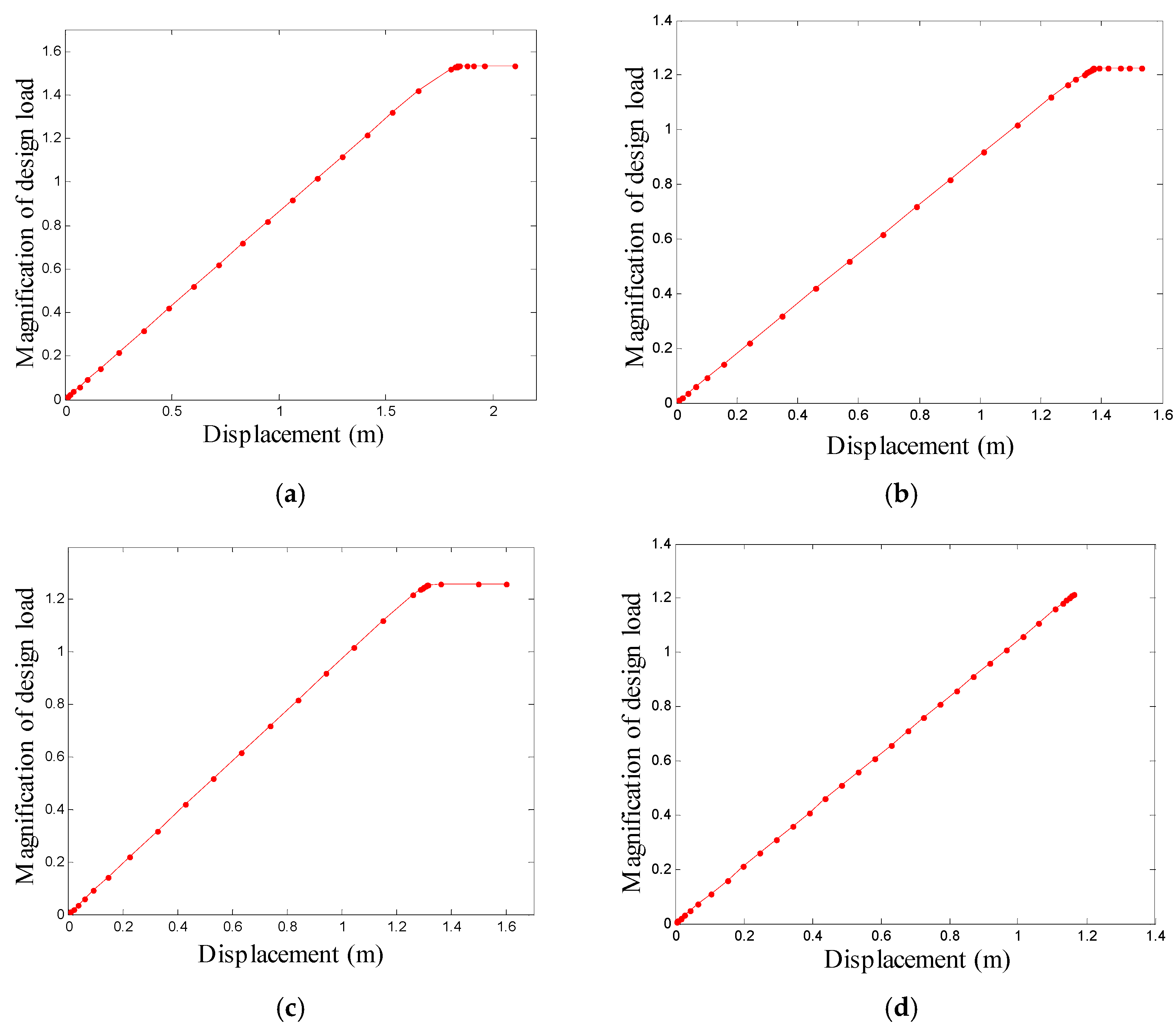
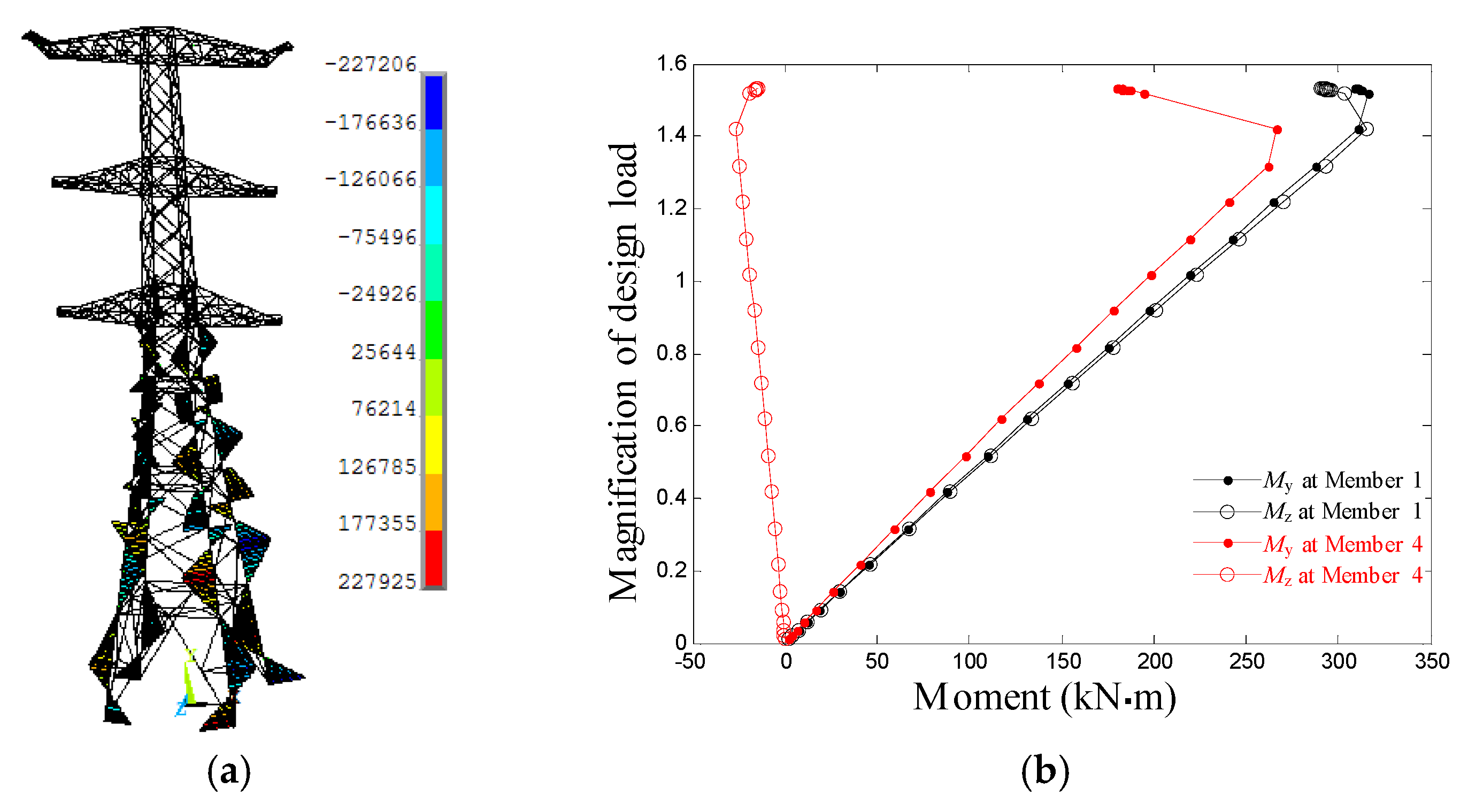
3. Structural Capacity Analysis of the Tower

According to the previous analysis, the tower is mainly in a linear elastic stress state under the design load, which indicates a conservative tower design. To excite its nonlinear characteristics, it is necessary to increase the load, so the following exhibits the analysis of the tower’s ultimate capacity.
The displacement at the top of the tower under a 90-degree wind load is shown in Figure 6a, where there is a clear inflection point. First, a linear relationship between load and displacement is shown in the range of 0–1.42 times the design load. Second, within the range of 1.42 to 1.53 times the design load, the strength or stability of some bars of the structure are damaged. The number of iterations and the density of load steps calculated by the procedure show that the stiffness of the structure changes greatly at this time, and that the internal forces of the structural bars begin to be redistributed. Third, when the load of 1.53 times the design load is exceeded, the displacement at the top of the tower under the action of a small load increases at a faster rate. Due to the excessive displacement, the program no longer converges, so 1.53 times the design load is considered to be the limit load for this working condition.
The variation of displacement with load at the tower top under 60-degree wind loads is shown in Figure 6b. In the range of 0 to 1.19 times the design load, the load and displacement are linearly related. Then, in the range of 1.19 to 1.23 times the design load, the structure enters the plastic deformation stage, and the corresponding limit load under this condition is 1.23 times the design load.
The variation of displacement with load at the top of the tower under 45-degree wind loads is shown in Figure 6c. In the range of 0 to 1.24 times the design load, the load and displacement are linearly related. Then, in the range of 1.24 to 1.26 times the design load, the structure enters the plastic deformation stage, and the corresponding ultimate load is 1.26 times the design load.
The variation of displacement with load at the top of the tower under 0-degree wind loads is shown in Figure 6d. The structural load and displacement show a linear relationship in the range of 0 to 1.22 times the design load, corresponding to a limit load of 1.22 times the design load.
The sustained load of the structural components below the cross arm is comparatively large; thus, the members on the compression side below the lower cross arm, which sustained the largest axial force, are selected. The numbering position and rules are shown in Figure 7. The mantissa of front numbering is 0 and 1, and the mantissa of the back numbering is 2 and 3. The axial force of the main member under the design load and the ultimate load of each calculation condition are shown in Table 3, Table 4, Table 5 and Table 6.
It can be seen that the ultimate bearing capacity under 90-degree wind conditions is about 48.8% higher than the axial force of the main material under the corresponding design load, i.e., that 48.8% of the load bearing margin of the tower structure has not been used. The ultimate bearing capacity under 60-degree strong wind conditions is 18.6% higher than the axial force of the main material under the design load on average. The ultimate bearing capacity under 45-degree wind conditions is 21.4% higher than the axial force of the main material under the design load on average. The ultimate bearing capacity is 16% higher than the axial force of the main material under the corresponding design load on average.

4. Analysis of Influent Factors on Secondary Stress

The distribution of secondary bending moments for typical 90-degree wind conditions is shown in Figure 8a. It can be seen that the maximum secondary bending moment of the main structural member of the tower occurs at both endpoints, and that the second moment is mainly concentrated in the main material part below the lower crossbeam. Figure 8b shows the variation of the bending moment with load in a 90-degree wind (note: the numbers 7330-7210 are for member 1 and 7010-2910 for member 4 in the figure). It can be seen that, before the load of 1.42 times the design load, the end moment is linearly increasing, and that the end moment gradually decreases as the loading continues. The secondary moment causes a plastic hinge at the end of the rod, which degrades the axial stiffness of the member and causes internal force redistribution.
This part mainly analyzes the secondary stresses under 60-degree wind loads, which mainly controls the primary material forces. Chen [24] has expressed belief that the yield secondary stresses of the tie bars have little effect, so they selected the bar on the compression side of the main material for analysis. The strength stress of the compressed bending member was calculated according to Equation (1), and the stability stress was calculated according to Equations (2) and (3).
σ = N A ± M x γ x W n x ± M y γ y W n y
σ = N φ x A + β m x M x γ x W x ( 1 0.8 N N E X ) + η β t y M y φ b y W y
σ = N φ y A + β m y M y γ y W y ( 1 0.8 N N E y ) + η β t x M x φ b x W x
N is the axial force on the main material, A is the cross-sectional area of the tube, γ x and γ y are cross-sectional plasticity development factors corresponding with cross-sectional moduli, which are both 1.15 for circular tube sections, M x and M y are bending moments around the x axis and the y axis at the same cross-section, and W n x and W n y are net cross-sectional modulus for the x and y axes, respectively. N E x = N E y = π 2 E A / ( 1.1 λ 2 ) is the stability factor for axially stressed members in the plane, M is the maximum bending moment within the calculated main material section, and W x and W y are the in-plane and out-of-plane gross section moduli, respectively. For the equivalent moment factor β m = 0.65 + 0.35 ( M 2 / M 1 ) , M 1 and M 2 are the bending moment at the end. When the component produces the same curvature (without recurved point), the ratio has the same sign, and when the component produces reverse curvature (with recurved point), the ratio has a different sign, | M 1 | ≥ | M 2 |. φ b x is the stability factor. The results of the calculations corresponding to the design and limit loads are shown in Table 7 and Table 8, respectively.
From the results of the calculations in Table 7 and Table 8, it can be seen that (1) the calculated stress corresponding to the design load partly exceeds the yield strength of 345 MPa, but that the whole tower can continue to bear the load until the limit state when most of the rods have plastic hinges. The reason for this is that the stresses at the end of the bar are concentrated, while the whole bar has not yielded at the full section and can continue to bear a greater load. This indicates that partial yielding of bars does not mean that the whole tower has lost its load-bearing capacity; the tower will be destroyed only when a certain number of bars yield and when yielding of the full section has been reached. (2) Section 8.4.5 in the Code for Structural Steel Design [25] limits secondary stresses to no more than 20% by limiting the ratio of bar length to the height of the section (L/D). Second-order stress should be considered when it is less than 12, but the analysis in this paper shows that the secondary stress ratio for bars that are greater than 12 also exceeds 20%. The effect of secondary stresses increases with the increase in L/D, so that it is not reasonable to continue to rely on the specification with empirical boundaries. (3) The distribution of secondary stresses decreases as the tower height increases, i.e., the secondary stresses in the tower legs have the greatest influence. (4) The proportion of secondary stress in the nonlinear phase is larger than that in the linear phase. The larger the load, the more significant the influence of secondary stress, so the load form is also one of the factors affecting the secondary stress.

5. Conclusions

In this paper, an FE model of an ultra-high voltage (UHV) steel tube tower that considers geometric and material nonlinearity is established, and the ultimate bearing capacities under different wind conditions are obtained. The secondary stresses are analyzed and following conclusions are drawn.
(1) The real tower test and elastoplastic ultimate bearing capacity analysis show that the UHV steel pipe tower designed according to the linear elasticity and small deformation theory has a large safety margin under the design load. Under the action of wind actions in different directions, 16–48.8% of the bearing capacity has not been fully utilized, which results in significant material waste. Reducing the structural stiffness of an ultra-high voltage transmission tower may result in undesirable seismic effects. Under the action of high load, the steel tower exhibits strong nonlinearity, and the influence of geometric and material nonlinear factors should be fully considered when designing steel tower components.
(2) The ultimate bearing capacity analysis of the truss tower shows that plastic hinges are first formed at the ends of the bars and gradually develop to the middle part. When the full section yielding members reach a certain number, the bars and towers lose the bearing capacity.
(3) Deploying the ratio of bar length to the height of section (L/D) that equals 12 as the threshold to deal with the secondary stress criterion has a deficiency. The analysis shows that the influence of the secondary stress of the main structural member increases with the increase of the ratio of L/D, and decreases with the increase of the tower height. The influence of the secondary stress of the tower leg should be considered. The proportion of secondary stress in the nonlinear stage is larger than that in the linear stage, i.e., a more significant influence of the secondary stress is incurred with a greater load, while the load form is also one of the factors affecting the secondary stress.

Author Contributions

Conceptualization, H.W.; methodology, L.Q. and Y.-R.D.; validation, R.L. and H.W.; investigation, R.L. and H.W.; writing—original draft preparation, R.L. and H.W.; writing—review and editing, R.L.; supervision, L.Q. and Y.-R.D.; project administration, L.Q. All authors have read and agreed to the published version of the manuscript.

Funding

The authors would like to offer their thanks for the support provided by the Scientific Research Foundation for Excellent Returned Overseas Chinese Scholars in Shaanxi Provincial Government (Grant No. 2021-017).

Data Availability Statement

Dataset available on request from the authors.

Conflicts of Interest

The authors declare that there is no conflict of interests regarding the publishing of this paper.

References

  1. Li, M.H.; Yang, J.B.; Li, Z.L. Analysis on secondary stress for steel-tube tower of 1000 kv double circuit transmission lines on same tower. Power Syst. Technol. 2010, 34, 20–23. [Google Scholar]
  2. J1733-2020; Technical Specification for the Design of Steel Supporting Structures of Overhead Transmission Line. China Planning Press: Beijing, China, 2020.
  3. Zhao, D.S. The Theoretical Analysis and Study of Mechanical Behaviour for Transmission Tower. Ph.D. Thesis, Zhejiang University, Hangzhou, China, 2003. [Google Scholar]
  4. Donovan, K. Structural Analysis of Transmission Tower with Connection Clip Modeling. Ph.D. Thesis, University of Manitoba, Winnipeg, MB, Canada, 2000. [Google Scholar]
  5. Albermani, F.G.A.; Kitipornchai, S. Numerical simulation of structural behaviour of transmission towers. Numerical simulation of structural behaviour of transmission towers. Thin-Walled Struct. 2003, 41, 167–177. [Google Scholar] [CrossRef]
  6. Albermani, F.; Kitipornchai, S.; Chan, R.W.K. Failure analysis of transmission towers. Eng. Fail. Anal. 2009, 16, 1922–1928. [Google Scholar] [CrossRef]
  7. Al-Bermani, F.G.A.; Kitipornchai, S. Nonlinear analysis of transmission towers. Eng. Struct. 1992, 14, 139–151. [Google Scholar] [CrossRef]
  8. Kong, W.; Li, H.; Du, Q. Dual nonlinear analysis of the ultimate load-bearing capacity of large-span transmission tower. Shanxi Electr. Power 2009, 3, 5–7. [Google Scholar]
  9. Deng, H.Z.; Wang, Z.M. A study for the limit strength and reliability of transmission tower structural system. Electr. Power Constr. 2000, 2, 12–14. [Google Scholar]
  10. Wang, J.; Sun, Q. Cyclic testing of Q690 circular high-strength concrete-filled thin-walled steel tubular columns. Adv. Struct. Eng. 2019, 22, 444–458. [Google Scholar] [CrossRef]
  11. Wang, J.; Sun, Q.; Wu, X.; Wu, Y. Experimental and analytical investigation on seismic behavior of Q690 circular high-strength concrete-filled thin-walled steel tubular columns. Struct. Des. Tall Spec. Build. 2019, 28, e1583. [Google Scholar] [CrossRef]
  12. Wang, J.T.; Wu, X.H.; Yang, B.; Sun, Q. Retrofitted built-up steel angle members for enhancing bearing capacity of latticed towers: Experiment. Steel Compos. Struct. 2021, 41, 681–695. [Google Scholar]
  13. Qu, S.Z.; Guo, Y.; Sun, Q. Resistances of high-strength steel equal-leg-angle section columns eccentrically connected by one leg. J. Constr. Steel Res. 2022, 191, 107143. [Google Scholar] [CrossRef]
  14. Qu, S.Z.; Wu, X.H.; Sun, Q. Experimental and numerical study on ultimate behaviour of high-strength steel tubular K-joints with external annular steel plates on chord circumference. Eng. Struct. 2018, 165, 457–470. [Google Scholar] [CrossRef]
  15. Zhou, S.M.; Sun, Q.; Wu, X. Impact of D/t ratio on circular concrete-filled high-strength steel tubular stub columns under axial compression. Thin-Walled Struct. 2018, 132, 461–474. [Google Scholar] [CrossRef]
  16. Wen, B.; Taciroglu, E.; Niu, D.T. Shake table testing and numerical analysis of transformer substations including main plant and electrical equipment interaction. Adv. Struct. Eng. 2015, 18, 1959–1980. [Google Scholar] [CrossRef]
  17. Shuai, Q.; Deng, H.Z.; Li, L.; Shi, J.H. Analysis on secondary stress of primary member of UHV transmission tower structure. J. Build. Struct. 2012, 33, 109–116. [Google Scholar]
  18. Han, J.K.; Yang, J.B. Value selection of slenderness ratio and diameter-thickness ratio of steel tube for 1000kV transmission steel tubular tower legs. Power Syst. Technol. 2009, 33, 17–20. [Google Scholar]
  19. Zhang, J.; Xie, Q. Failure analysis of transmission tower subjected to strong wind load. J. Constr. Steel Res. 2019, 160, 271–279. [Google Scholar] [CrossRef]
  20. Xue, J.Y.; Xiang, Z.M.; Ou, G. Predicting single freestanding transmission tower time history response during complex wind input through a convolutional neural network based surrogate model. Eng. Struct. 2021, 233, 111859. [Google Scholar] [CrossRef]
  21. Roy, S.; Kundu, C.K. State of the art review of wind induced vibration and its control on transmission towers. Structures 2021, 29, 254–264. [Google Scholar] [CrossRef]
  22. Yang, J.B.; Han, J.K.; Li, M.H.; Li, F.; Yang, F.L. Selection of Calculation Model for Steel Tubular Tower of UHV Power Transmission Line. Power Syst. Technol. 2009, 34, 1–5. [Google Scholar]
  23. DL/T 5154-2002; Technical Regulations for the Design of Overhead Transmission Line Tower Structure. Electric Power Press: Beijing, China, 2002.
  24. Chen, S.F. Secondary stress and ultimate state of steel trusses. Steel Constr. 2005, 20, 1–4. [Google Scholar]
  25. GB50017-2003; Code for Design of Steel Structures. China Architecture Industry Press: Beijing, China, 2011.
Figure 1. Tower SZ322P.
Buildings 14 00140 g001
Figure 2. Layout of displacement (unit: m).
Buildings 14 00140 g002
Figure 3. Displacement cloud in FEA (unit: m).
Buildings 14 00140 g003
Figure 4. Displacement comparisons.
Buildings 14 00140 g004
Figure 5. Stress contour at critical points. (a) Elevation at 2.4 m and (b) elevation at 16.4 m.
Buildings 14 00140 g005
Figure 6. Load–displacement curve at tower top. (a) Under 90° wind, (b) under 60° wind, (c) under 45° wind, and (d) under 0° wind.
Buildings 14 00140 g006
Figure 7. Member numbers.
Buildings 14 00140 g007
Figure 8. Illustration of secondary moment. (a) Distribution contour and (b) moment variation.
Buildings 14 00140 g008
Table 1. Cross-sectional size for structural members (mm).
CategoryConnection between Tube and Joint RegionCross SectionTotal Number
Tower main bodyU style∅102–∅27322
C style∅89–∅29923
X style∅114–∅42631
Diagonal materialU style∅102–∅42634
C style∅89–∅37728
X style∅114–∅42631
Accessory memberC style∅75–∅40635
Table 2. Comparisons of displacement (mm).
Observation
Point
90-Degree Wind Load60-Degree Wind Load
FEATestFEATest
x Directionz Directionx Directionz Directionx Directionz Directionx Directionz Direction
111464731237417921416842353
210083801037336763335700284
3511338549348430305408284
4218256257265183235189281
51005461026468485776552
651146549444315741652
721935261291854419135
81132813026953610827
92416521326203918
101102−341119−24846−10759−5
Table 3. Comparison of axial force under 90° wind (kN).
Member NumberDesign LoadUltimate LoadRatio (%)
7330-7210−5449.5 −8167.6 49.9
7210-7110−5464.5 −8183.3 49.8
7110-7010−5503.2 −8247.1 49.9
7010-2910−5792.6 −8452.4 45.9
2910-2810−5536.7 −8235.1 48.7
2810-2730−5542.6 −8243.3 48.7
2730-2710−5711.5 −8479.2 48.5
2710-2510−5722.4 −8536.5 49.2
2510-2110−5205.6 −7765.9 49.2
2110-1610−4641.7 −6894.8 48.5
Table 4. Comparison of axial force under 60° wind (kN).
Member NumberDesign LoadUltimate LoadRatio (%)
7330-7210−6912.2 −8170.1 18.2
7210-7110−6929.2 −8186.1 18.1
7110-7010−6984.1 −8263.4 18.3
7010-2910−7334.1 −8635.9 17.7
2910-2810−7015.0 −8304.4 18.4
2810-2730−7022.2 −8310.9 18.4
2730-2710−7245.6 −8616.2 18.9
2710-2510−7276.0 −8681.1 19.3
2510-2110−6618.6 −7896.3 19.3
2110-1610−5883.0 −7001.5 19.0
Table 5. Comparison of axial force under 45° wind (kN).
Member NumberDesign LoadUltimate LoadRatio (%)
7330-7210−6774.5 −8207.4 21.2
7210-7110−6791.5 −8222.9 21.1
7110-7010−6845.2 −8295.2 21.2
7010-2910−7180.0 −8659.5 20.6
2910-2810−6859.1 −8313.0 21.2
2810-2730−6866.2 −8319.8 21.2
2730-2710−7073.6 −8615.5 21.8
2710-2510−7093.8 −8672.7 22.3
2510-2110−6457.8 −7890.0 22.2
2110-1610−5732.2 −6985.5 21.9
Table 6. Comparison of axial force under 0° wind (kN).
Member NumberDesign LoadUltimate LoadRatio (%)
7330-7210−4625.6 −5309.3 14.8
7210-7110−4638.6 −5323.8 14.8
7110-7010−4661.2 −5392.6 15.7
7010-2910−4905.8 −5660.2 15.4
2910-2810−4674.6 −5435.0 16.3
2810-2730−4680.0 −5441.6 16.3
2730-2710−4816.1 −5620.2 16.7
2710-2510−4833.1 −5640.7 16.7
2510-2110−4405.6 −5155.4 17.0
2110-1610−3910.8 −4559.5 16.6
Table 7. Stress calculation of beam model (design load).
Member
Number
Axial Force
/kN
Mxi
/kN•m
Mxj
/kN•m
Myi
/kN•m
Myj
/kN•m
Diameter
/m
Thickness
/m
Slenderness
Ratio λ
Axial Stress
/MPa
Strength
Stress
/MPa
Stability
Stress
/MPa
Maximum Stress/Axial StressRod Length/
Diameter
7330-7210−6912.16279.04−233.44281.60−243.860.660.01438−243.40−351.95−364.651.5013.09
7210-7110−6929.19−238.49−2.14−248.767.530.660.01438−244.00−338.34−330.861.3913.09
7110-7010−6984.133.61152.4211.8077.040.630.01433−257.91−306.96−312.421.2111.29
7010-2910−7334.12154.70−131.9877.70−80.740.610.01435−279.93−338.95−358.291.2812.16
2910-2810−7015.04−87.85−133.89104.3682.060.610.01427−267.75−322.03−306.771.209.16
2810-2730−7022.16−81.56136.44−100.5967.960.610.01424−268.02−322.03−325.971.228.33
2730-2710−7245.55136.89−67.6568.93−36.800.610.01429−276.55−348.72−333.861.2610.00
2710-2510−7276.00−127.81−66.27179.8735.360.610.01422−277.71−347.81−325.851.257.50
2510-2110−6618.62−118.4364.65−177.8858.580.610.01427−252.62−320.13−320.081.279.35
2110-1610−5883.0065.72−39.8056.91−96.520.610.01424−224.54−252.48−267.371.198.20
Note: Mx and My are the in-plane and out-of-plane bending moments in the table, respectively, and i and j represent the ends of the bar. The maximum stress is selected as the larger value of strength and stable stress.
Table 8. Stress calculation of beam model (ultimate load).
Member
Number
Axial Force
/kN
Mxi
/kN•m
Mxj
/kN•m
Myi
/kN•m
Myj
/kN•m
Diameter
/m
Thickness
/m
Slenderness
Ratio λ
Axial Stress
/MPa
Strength
Stress
/MPa
Stability
Stress
/MPa
Maximum Stress/Axial StressRod Length/
Diameter
7330-7210−8170.10292.31−253.46292.25−262.170.660.01438−243.40−400.88−418.881.7213.09
7210-7110−8186.08−259.0111.03−267.6117.560.660.01438−244.00−390.22−386.181.6013.09
7110-7010−8263.3616.55110.8121.8052.680.630.01433−257.91−339.74−356.381.3811.29
7010-2910−8635.86109.37−101.6751.45−58.390.610.01435−279.93−379.42−402.521.4412.16
2910-2810−8304.37−89.28−104.45109.2459.760.610.01427−267.75−365.65−357.981.379.16
2810-2730−8310.89−83.68113.02−106.0748.330.610.01424−268.02−367.13−375.241.408.33
2730-2710−8616.23110.92−57.2948.67−6.380.610.01429−276.55−371.79−383.211.3910.00
2710-2510−8681.15−43.34−50.5277.47−0.610.610.01422−277.71−362.53−361.821.317.50
2510-2110−7896.29−37.9865.54−86.3735.030.610.01427−252.62−336.00−349.991.399.35
2110-1610−7001.4665.18−48.4031.62−82.170.610.01424−224.54−289.29−309.101.388.20
Disclaimer/Publisher’s Note: The statements, opinions and data contained in all publications are solely those of the individual author(s) and contributor(s) and not of MDPI and/or the editor(s). MDPI and/or the editor(s) disclaim responsibility for any injury to people or property resulting from any ideas, methods, instructions or products referred to in the content.

