Article

Preparation and Properties of Double Liquid Grouting Materials (DLGMs) Used for the Regenerated Roof of a Coal Mine

1
Anhui Province Engineering Laboratory of Advanced Building Materials, Anhui Jianzhu University, Hefei 230601, China
2
College of Materials Science and Engineering, Nanjing Tech University, Nanjing 211800, China
3
Pingan Coal Mining Engineering and Technology Research Institute Co., Ltd., Huainan 232033, China
*
Authors to whom correspondence should be addressed.
Buildings 2023, 13(3), 584; https://doi.org/10.3390/buildings13030584
Submission received: 2 January 2023 / Revised: 30 January 2023 / Accepted: 20 February 2023 / Published: 22 February 2023

Abstract

:
Double liquid grouting materials (DLGMs) are composed of slurry A and slurry B. In response to the need for sustainable development, there is currently a focus on improving the utilization rate of resources. In this paper, industrial solid waste fly ash, slag, and ordinary Portland cement were used to prepare slurry A, while sodium silicate was used as slurry B. Slurry C was made by adding slurry B to slurry A. The mix design parameters of the DLGMs, with large amounts of fly ash, were optimized based on the response surface method. The results showed that the relative content of cement and the reactivity and morphological effect of supplementary cementitious materials (fly ash and slag) were the main factors affecting the operable time, viscosity, and stability of slurry A. The relative content of cement and the sodium silicate modulus were the main factors affecting the operable time of the DLGMs. Compared to the C30F70S0-Z3.3 group (where C, F, S, and Z represented cement, fly ash, slag, and sodium silicate modulus, respectively), the operable time of the C0F70S30-Z3.3 group increased by approximately 36 min. As the sodium silicate modulus was lowered to 2.3, the operable time of the C0F70S30-Z2.3 group increased by about 32 min compared to that of the C30F70S0-Z2.3 group. The established model and response surface can well reflect the influence of multiple factors on the properties of the DLGMs. When the mass ratio of cement/fly ash/slag in slurry A was 7.5%: 70%: 22.5%, and the sodium silicate modulus and content of slurry B were 2.8 and 10%, respectively, the 28-day compressive strength of the DLGMs can reach up to 11.3 MPa. The content of fly ash was the most significant factor affecting the 28-day compressive strength of the DLGMs, followed by the sodium silicate content. The least influential factor was the sodium silicate modulus. The XRD and SEM results showed that a large amount of Ca2+ produced by cement hydration can quickly react with [SiO4]4- in sodium silicate to form C-S-H gel. Moreover, it also promoted the hydration of C3S and C2S in grouting to produce more C-S-H gel, which was conducive to the alkali activation of slag and fly ash, resulting in a denser microstructure and hence, yielded obvious increases in the compressive strengths of the DLGMs.

1. Introduction

China holds a sizeable number of the thick coal seams; it is also a country that participates in the large-scale mining of thick coal seams. The coal output from the thick coal seam accounts for about 45% of the total production of raw coal [1,2]. Currently, the technology of thick-coal seam mining includes the fully-mechanized and full-seam mining method, the slice mining method, and the top-coal caving mining method [3,4,5]. Slice mining is the dominant mining technology for the thick coal seams in China, and it has also been the main development direction for coal mining technology throughout the world [6]. Grouting technology, which is often used in foundation reinforcement, is a type of comprehensive technology applied in construction engineering. According to different building conditions, the basic performance requirements of grouting materials are different. Notably, during top layered mining in the slice mining of thick coal seams, goaf grouting has been carried out to prevent natural fires in the goaf and to promote the formation of regenerated roofs [7,8,9]. During stratified mining, the regenerated roof matrix mainly consists of the natural consolidation or artificial cementation of the caving gangue in the upper layer. At this stage, the basic grouting materials used in coal mines are clay grouting materials, cement-based grouting materials, and fly ash grouting materials [10,11,12,13,14]. However, these three grouting materials exhibit their own shortcomings. For example, clay grouting materials not only consume considerable land resources, but also possess low strength, poor stability, and large plastic deformation. Thus, the roof is prone to separation collapse and a longer regeneration cycle. Cement-based grouting material possesses more problems, e.g., high costs, rapid setting time, severe shrinkage in the later stage, high hydration heat release, and high grouting technology requirements [15,16,17,18,19,20]. Fly ash, a solid waste discharged from coal-fired power plants, shows pozzolanic reactivity, morphological effects, and micro-aggregate filling when used for supplementary cementitious materials [21,22,23]. The main morphology of fly ash particle is spherical, and the particle size is finer, exhibiting good spherical lubrication and drag reduction characteristics; therefore, the fly ash grouting material shows good irrigation and permeability [24]. However, the pure fly ash grouting material yields poor viscosity, cementing properties, suspension, and water retention. Therefore, it is urgent to develop a green, low-cost, high-performance regenerated roof grouting material for use in coal mines.
The DLGM is composed of suspended turbidity slurry (slurry A) and sodium silicate (slurry B). It has the characteristics of rapid setting time, low leakage, and well fire resistance [25,26]. In addition, materials with good performance in regards to mechanical properties, impermeability, and stability [27,28,29] can achieve timely filing, reinforcement, waterproofing, and plugging, which are widely used in tunnel wall grouting, curtain grouting, soft foundation reinforcement, and other projects. Wang et al. [30] proposed a long-term performance evaluation method based on cement-sodium silicate slurry. For this study, they revealed the distribution pattern of reaction products in cement-sodium silicate grouting and its alterations in response to variations in sodium silicate content. Zhu et al. [31] studied the influence of the operation time of cement and sodium silicate slurry by using the flip cup method and analyzed the influencing factors of viscosity of DLGMs, which provided an appropriate direction for the parameter design of grouting material. The excellent properties of the DLGMs give them great application potential in the coal mining industry. It is worth noting that the grouting material used for the regenerated roofs in coal mines requires good flow performance, stability, and rapid operation time. It must also exhibit good cementing performance after the slurry has hardened. Furthermore, the demand for grouting materials is high; therefore, great effort should be made to reduce the economic costs of grouting materials as much as possible. The progress of coal mining engineering leads to upper roof overhang and finally, upper roof collapse under pressure from the upper coal seam and rock, with a large amount of gravel appearing in the goaf. In order to more efficiently utilize resources, sustainable development must be resource-oriented. The design of low-cost and high-performance grouting materials applied in the reinforcement of the crushed roof rock of coal mining projects is worthwhile for the establishment of the upper roof of coal mines and the effective shortening of the coal mining cycle, consequently increasing economic benefits. In view of the above unresolved problems, fly ash was adopted as the dominant raw material, accompanied by slag powder and cement, to prepare suspension-type slurry A, and the influence of raw material composition on the performance of slurry A was studied. Sodium silicate was used as slurry B, and the effects of fly ash content, sodium silicate content, and sodium silicate modulus on properties of the DLGMs (slurry C) were then investigated, based on the response surface method (RSM). Additionally, the compositions and microstructures of the DLGMs were analyzed via XRD and SEM. This study provides a theoretical basis and technical support for the design and preparation of the DLGMs with low-carbon, low-costs, and high-performance.

2. Materials and Methods

2.1. Materials

Fly ash (FA) was provided by a thermal power plant in Huainan, Anhui Province, and slag (SG) was provided by Wuhan Huashen Intelligent Technology Limited Company. Figure 1 shows the micromorphologies of fly ash and slag. The Portland cement (CM) was produced by Anhui Conch Cement Limited Company. Table 1 shows the chemical composition of raw materials. Sodium silicate (WG) was provided by Huainan Hongrui Building Materials Technology Limited Liability Company. Its Baume degree was 39.2, the modulus was 3.3, and the content of Na2O, SiO2, and H2O was 8.51%, 27.29%, and 63.6%, respectively. The composition of raw materials in Table 1 is measured using XRF. Tap water was used for the experiments.

2.2. Design and Preparation of Grouting Materials

2.2.1. Preparation of Slurry A

To explore the influence of the ratio of cement/fly ash/slag on the performance of slurry A, several sets of experiments were designed, and Table 2 shows the experimental mix ratio. The water to binder ratio was 1.0, where C, F, and S represented cement, fly ash, and slag, respectively. The right-side numbers in the Table show the mass percentages of the various raw materials in the cementitious material. The mixing time of each group of raw materials was no less than 3 min in the cement mortar mixer. Homogenized slurry A was used to test the settling rate, viscosity, and operable time.

2.2.2. Preparation and Optimization of Slurry C

Slurry A was prepared according to the mix ratio in Table 3, sodium silicate was selected as slurry B, and slurry C was prepared by mixing the ratio of slurry A: slurry B = 3:1, and stirring evenly. The influence of the raw material composition and the sodium silicate modulus on the operable time of slurry C was studied. The ZX indicated sodium silicate and its modules in Table 3 (x = 2.3, 2.8, and 3.3).
After verifying the effect of the raw materials composition and the sodium silicate modulus on the operable time of slurry C, the fly ash content was increased. The preparation parameters of the DLGMs were optimized based on the response surface method. With fly ash content (X), sodium silicate content (Y), and sodium silicate modulus (Z) as the factors, and the compressive strength of the slurry C mortars (slurry C to sand ratio = 1:3) as the response value, the mortar performance of the grouting materials with a high fly ash content was evaluated. The Box–Behnken surface method [11,32] was adopted to optimize the design parameters of the DLGMs. The three factors and three levels of the test design are shown in Table 4, and Table 5 shows the design scheme of the response surface test. The mass ratio between the slag and the cement remained 3:1. The percentage of sodium silicate content was calculated by the mass ratio of slurry A.

2.3. Test Method

The determination of the operable time of the grouting materials refers to JC/T 2536-2019 [33]. The adopted pouring cup method was used to test the operable time of the grouting. The cup was filled with 200 mL of slurry materials, and the setting time was counted. The slurry materials were recurrently slanted at 45° to observe the change, and the time elapsed for the grouting materials slurry to lose fluidity was defined as the operable time.
The viscosity of the grouting materials slurry was measured according to the test method for cement slurry viscosity. The slurry was homogeneously mixed and poured through the screen into the 1006 funnel mud viscometer, and fingers block the lower outlet of the viscometer. Subsequently, 700 mL of slurry was poured into the 1006 slurry viscometer, a 500 mL measuring cup was placed directly below the slurry outlet, the finger was released, and the count started. When the slurry overflowed the full cup, the counting stopped. The viscosity of the DLGMs was indicated by the time required for 500 mL of slurry to flow into the viscometer.
The settling rate of the grouting material was determined by pouring the well-mixed grouting material slurry into a 100 mL measuring cylinder. The recorded scale of the slurry suspension was variously located at 0 min, 1 min, 5 min, 10 min, 20 min, 30 min, 60 min, 120 min, and 180 min, respectively. Then, the slope of the linear fit was used to indirectly evaluate the settling rate of the slurry by linearly fitting the scale values of the slurry in the 100 mL cylinder at different times.
The compressive strength of the slurry of the DLGMs was achieved, according to GB/T 17671-2020 [34]. Samples made in 40 mm × 40 mm × 40 mm, were unmolded after 24 h for standard curing, and the YAW-2000 electro-hydraulic servo universal testing machine was adopted to test the 28-day compressive strength of the samples, with a loading rate of 0.2 MPa/s. A small amount of hardened slurry A and slurry C was obtained to terminate the hydration by anhydrous ethanol after 28 days of standard curing. A few samples were ground and sieved through 200 mesh. Then, the samples were dried in a vacuum dry oven at 50 °C for 24 h. The mineral composition of the samples was scanned and tested by a Rigaku D/max-2500 X-ray diffractometer. The samples were dried in a vacuum dry oven at 50 °C for 24 h. A dust canister was adopted to clear the surface after gold was sprayed on the samples. Scanning electron microscopy (Phenom Pharos G2 type) was chosen to observe the microscopic morphology of the samples.

3. Results and Discussion

3.1. Influence of Raw Material Composition on the Performance of Slurry A

3.1.1. The Operable Time of Slurry

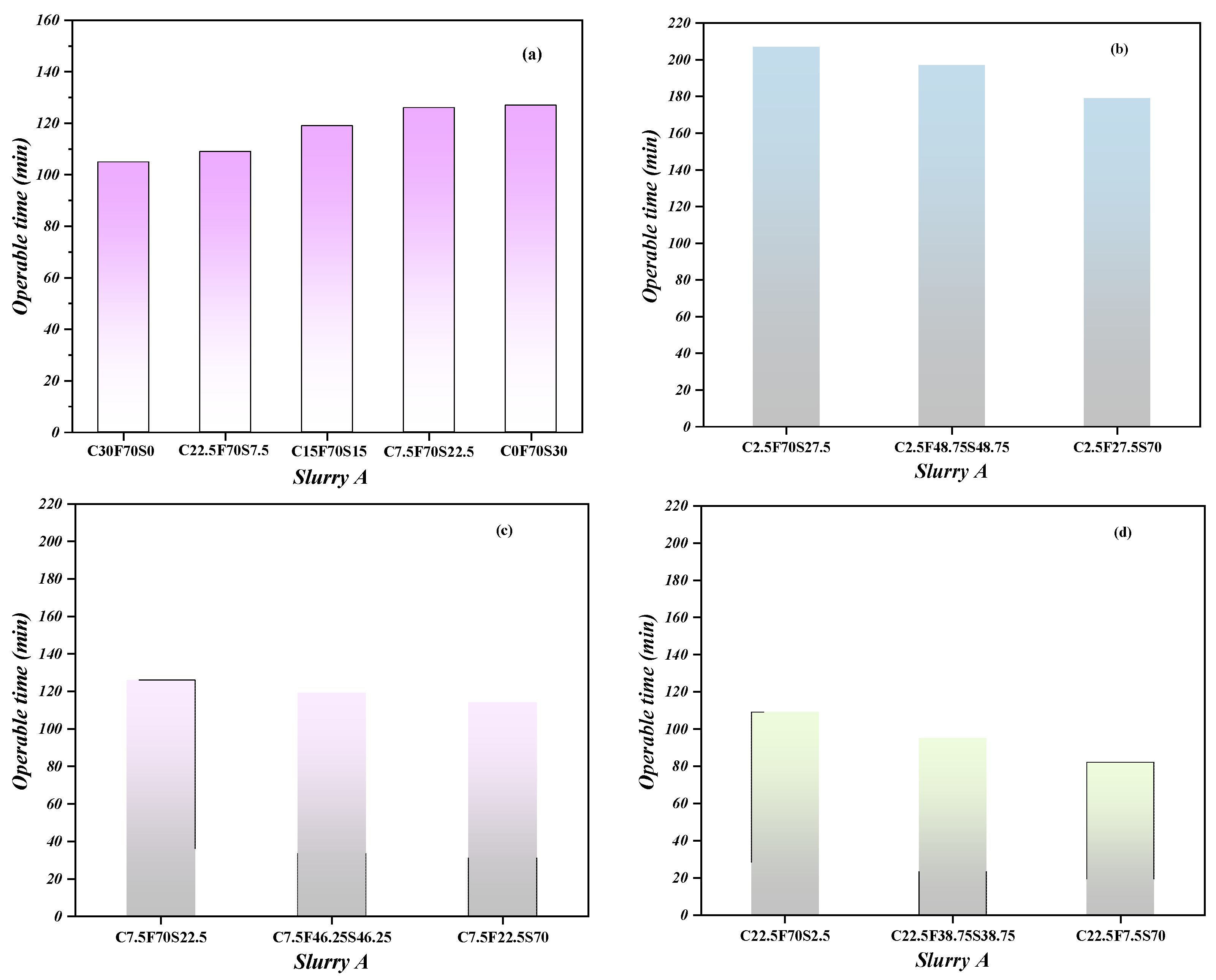
The operable time is an important parameter that affected the flow and irrigation performance of the grouting materials [17]. Figure 2 shows the effect of different compositions of raw materials on the operable time of slurry A. As the fixed mass fraction of fly ash in the system (70%), the operable time of slurry A gradually grew with the slag replacement by cement, among which the C30F70S0 group exhibited the feature of the shortest operation time, and the slurry lost its fluidity after 105 min. The operable time of the C0F70S30 group was delayed by 20.9% compared to that of the C30F70S0 group (Figure 2a). This might be related to the fact that an amount of fly ash (70%) existed in the suspension turbidity type slurry A. In the system with relatively lower cement contents, the hydration products, such as C-S-H gel or Ca(OH)2, were found to be lower in the early stages. The particle surface and the surrounding fly ash and slag scarcely formed the network structure in the initial reaction stage, which prolonged the operable time of slurry A.
The influence of the raw material composition on the operable time of slurry A was further studied by changing the proportions of fly ash and slag, while the mass percentage of cement in the cementing material was fixed (2.5%, 7.5%, and 22.5%). The experimental results are shown in Figure 2b–d, respectively. When the content of fly ash was constant, the operable time of slurry A decreased with the increase in the slag replacement. When the cement content was 2.5%, the operable time of the C2.5F27.5S70 group was reduced by 13.5% compared to the C2.5F70S27.5 group (Figure 2b). When the cement content was 7.5%, the operable time of the C7.5F22.5S70 group was reduced by 9.5% compared to the C7.5F70S22.5 group (Figure 2c). When the cement content was 22.5%, the operable time of the C22.5F7.5S70 group was 24.8% lower than that of the C22.5F70S7.5 group (Figure 2d). This might be a result of the Ca(OH)2, produced by cement hydration, providing the alkaline environment for the secondary hydration reaction with slag and fly ash. The higher the cement content in the grout, the higher the Ca(OH)2 content of the hydration product generated, and the more favorable it will be for the reaction with slag and fly ash [35,36]. However, the reactivity of slag was higher than that of fly ash, so different results were produced under different alkali environments. When the fly ash content was 70%, the operable time of the C22.5F70S7.5 group was reduced by 47.3% compared to that of the C2.5F70S27.5 group. When the slag content was 70%, the operable time of the C22.5F7.5S70 group was shortened by 54.2% compared to that of the C2.5F27.5S70 group. It can be seen that the relative content of cement and the relative reactivity of supplementary cementitious materials may be the main factors affecting the operable time of slurry A.

3.1.2. Viscosity of the Slurry

The viscosity of the slurry is an important property determining the flowability of a fluid [37]. The higher viscosity causes the lower flowability of the slurry. Figure 3 shows the influence of raw material composition on the viscosity of slurry A. When the cement content is fixed, the viscosity of slurry A decreased with the increase in the fly ash substituted slag content. When the cement content was 2.5%, the viscosity of the C2.5F70S27.5 group was 13.4% lower than that of the C2.5F27.5S70 group (Figure 3a). When the cement content was 7.5%, the viscosity of the C7.5F70S22.5 group was 7.9% lower than that of the C7.5F22.5S70 group (Figure 3b). When the cement content was 22.5%, the viscosity of the C22.5F70S7.5 group was 18.3% lower than that of the C22.5F7.5S70 group (Figure 3c). This may be due to the micro ball effect of fly ash in grouting material slurry A, which reduced the friction resistance caused by the relative movement of particles in the fluid and thus reduced the grouting viscosity. With 70% contents of fly ash, the slurry viscosity of the C22.5F70S7.5 group was reduced by 7.8% compared to that of the C2.5F70S27.5 group. As the slag replacement content of fly ash increased to 70%, the slurry viscosity of the C22.5F7.5S70 group was reduced by 2.3% compared to that of the C2.5F27.5S70 group. This may be attributed to the assistance that hydration products, such as C-S-H gel, produced by cement hydration, reduced the frictional resistance when the relative motion occurred between particles within the slurry. The above results indicated that the slurry viscosity of grouting material slurry A might be mainly affected by the relative content of cement, fly ash, and slag.

3.1.3. Stability of Slurry

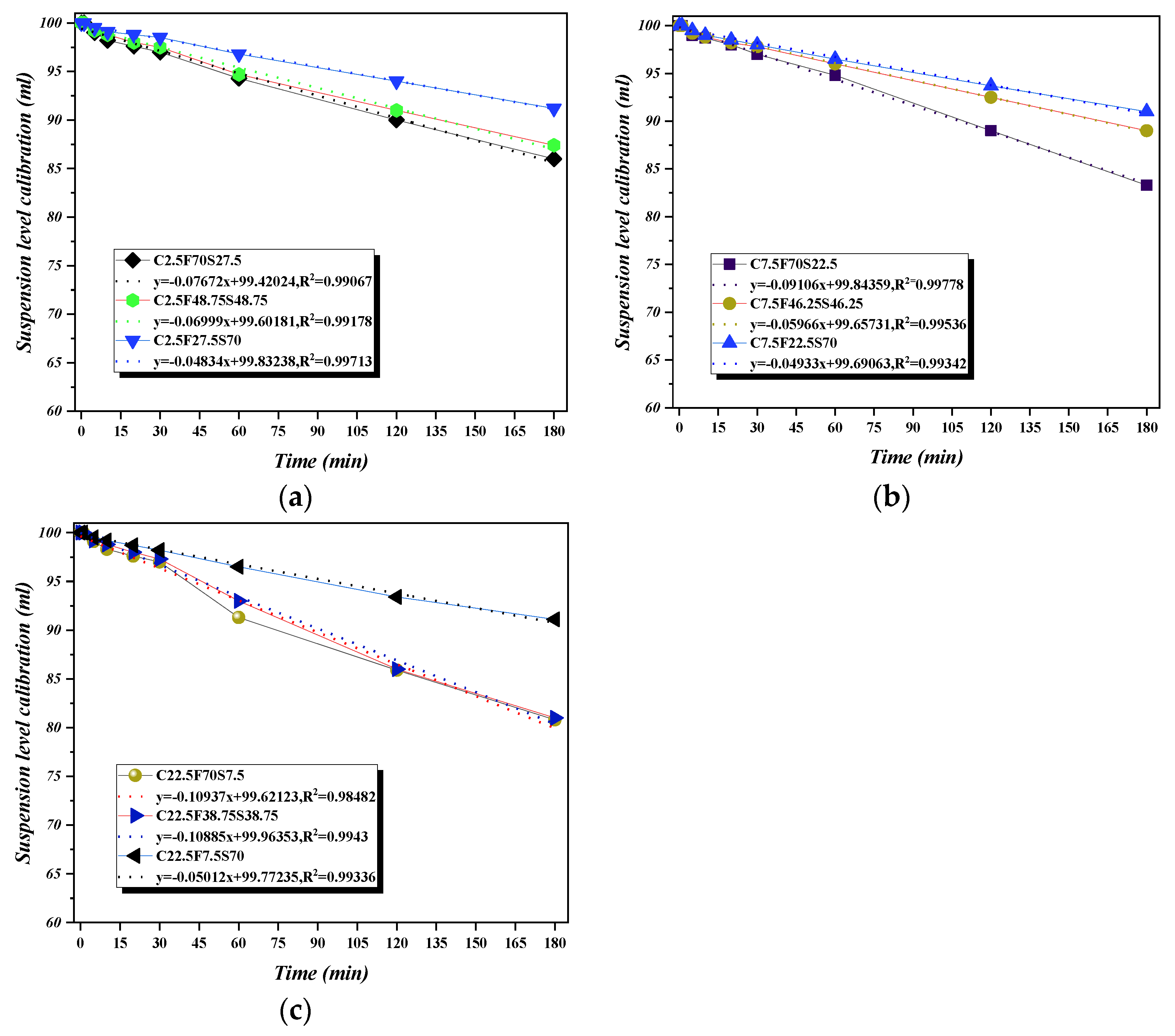
Slurry stability refers to the uniform degree of particle dispersion and suspension ability in the grouting. Figure 4 shows the influence of raw material compositions on the stability of slurry A. When the water-binder ratio was 1.0, the stability of slurry A in a 100 mL cylinder decreased with the extension of time. With the fixed cement content, the settlement rate of slurry A was shortened with the decrease in fly ash replacing slag in the system. When the cement content was 2.5%, the settlement rate of the C2.5F27.5S70 group was 37.0% lower than that of the C2.5F70S27.5 group. When the cement content was 7.5%, the settlement rate of the C7.5F22.5S70 group was 45.8% lower than that of the C7.5F70S22.5 group. However, when the cement content was 22.5%, the settlement rate of the C22.5F7.5S70 group was 54.2% lower than that of the C22.5F70S7.5 group. The above results may be related to the secondary hydration reaction between highly reactive slag and the cement hydration product Ca(OH)2 [38], which reduced the settlement rate of particles in the grouting. As the fly ash content increased to 70%, the slurry settlement rate of the C2.5F70S27.5 group was reduced by 29.9% compared to that of the C22.5F70S7.5 group, but when the slag content was 70%, the grouting settlement rate of the C2.5F27.5S70 group was reduced by 3.6% compared to that of the C22.5F7.5S70 group, which may be due to the relatively high content of cement in the system and the secondary hydration products of cement hydration product Ca(OH)2, and the active powder improved the suspension capacity of particles in the grouting. Therefore, the relative content of cement and the relative reactivity of supplementary cementitious materials (fly ash and slag) cause the main factors affecting the stability of grouting material slurry A.

3.2. Effect of Raw Material Composition and Sodium Silicate Modulus on the Operable Time of Slurry C

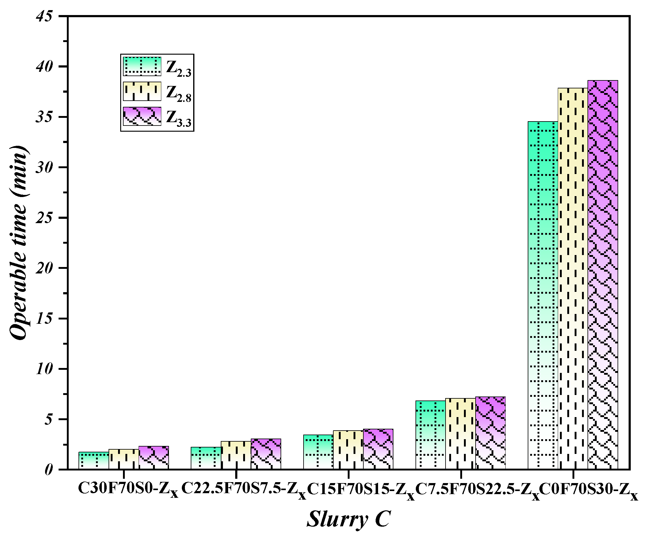
Sodium silicate was selected as slurry B of the DLGMs, and it was mixed with slurry A to prepare slurry C. Figure 5 shows the influence of the raw material composition and the sodium silicate modulus on the operable time of slurry C. Compared to Figure 2a and Figure 5, the operable time of slurry C was significantly shortened. Likewise, compared to the C30F70S0-Z3.3 group, its operable time was obviously shortened, which was probably due to the rapid reaction of sodium silicate in the slurry C contact with the hydration products of cement [39]. When the content of fly ash was constant, increasing the slag content resulted in the increase in the operable time of slurry C. For instance, the operable time of the corresponding slurry C can be extended to 38 min with the pure slag completely replacing the cement (Sample the C0F70S30-Z3.3); however, the cement content of the C30F70S0-Z3.3 group was higher, and the condensation failed to achieve fluidity at about 2 min. As the sodium silicate modulus was lowered to 2.3, the operable time of the C0F70S30-Z2.3 group increased by about 32 min compared to that of the C30F70S0-Z2.3 group. This trend could also be found when the modulus of sodium silicate was 2.8. In terms of the result, adding sodium silicate to slurry A may significantly promote the hydration of cement in the system and the dissolution and reconstruction of chemical bonds of highly reactive slag. Thus, the dissolved Ca2+ in the system rapidly reacted with the sodium silicate [SiO4]4− to form C-S-H gel [40,41], which may result in the rapid setting of slurry C. When the replacement of slag to cement in the system increased, the dissolution rate of Ca2+ decreased, and the formation of C-S-H gel was limited, which extended the operable time of slurry C.
The operable time of slurry C was also affected by the change in sodium silicate modulus, and the operable time of slurry C was shortened with the decrease in the sodium silicate modulus. When the cement content was 30%, the operable time of the C30F70S0-Z3.3 group, the C30F70S0-Z2.8 group, and the C30F70S0-Z2.3 group was 2 min 16 s, 1 min 57 s and 1 min 40 s, respectively. When all the cement was replaced by slag, the operable time of the C0F70S30-ZX group decreased more obviously with the decrease in the sodium silicate modulus. Compared to the C0F70S30-Z3.3 group, the operable time of the C0F70S30-Z2.3 group decreased by 10.6%, which might be due to the higher alkalinity of the sodium silicate with the low modulus. A more obvious dissolution effect on the chemical bond of active slag was confirmed, which was more conducive to the dissolution of the Ca2+ ions in slag [42]. This promoted the rapid formation of C-S-H gel, shortening the operable time of slurry C. Consequently, the raw material composition and the sodium silicate modulus were critical determinants affecting the operable time of slurry C.

3.3. The Effect of Interaction on the Mechanical Properties of the DLGMs

As previously mentioned, the raw material composition and mix ratio are critical parameters affecting the properties of the DLGMs. The demand for grouting materials remains vast in the regenerated roofs of coal mines, so performance and economic costs must still be considered. To ensure the high mortar strength of the grouting material, increasing the content of fly ash in the system is an effective method to mitigate the economic costs of the DLGMs. Moreover, based on the response surface method, with large amount of fly ash, the preparation parameters of the DLGMs were optimized. Table 6 shows the compressive strength of the DLGMs mortars at the age of 28 days.
Design Expert 12 software was used to conduct the numerical analysis of the data, and a multiple quadratic regression equation was established for the evaluation of the compressive strength of DLGMs mortars (F) and the factors (fly ash content (X), sodium silicate content (Y), and sodium silicate modulus (Z)) as follows:
F = 6.78 − 3.57X − 1.77Y − 1.23Z + 0.2250XY + 1.03XZ − 0.22507YZ − 0.3025X2 − 0.2525Y2 − 1.65Z2
Table 7 presents the variance analysis of the second-order response surface model of the compressive strength of the DLGMs. The correlation coefficient R2 and the p-value were used to evaluate the significance of the response model of the 28-day compressive strength of the DLGMs. The p-value of the regression model was <0.0001 and <0.05 (p ≤ 0.01 was high significance, p ≤ 0.05 was significant, p > 0.05 was low significance), and the regression model was highly significant. The R2 value was 0.9870, which indicated that the fitted regression models were reliable to predict the test results. According to the p-value, the degree of influence of the factors on the 28-day compressive strength of the DLGMs mortar, from high to low, was fly ash content (X), sodium silicate content (Y), and sodium silicate modulus (Z).
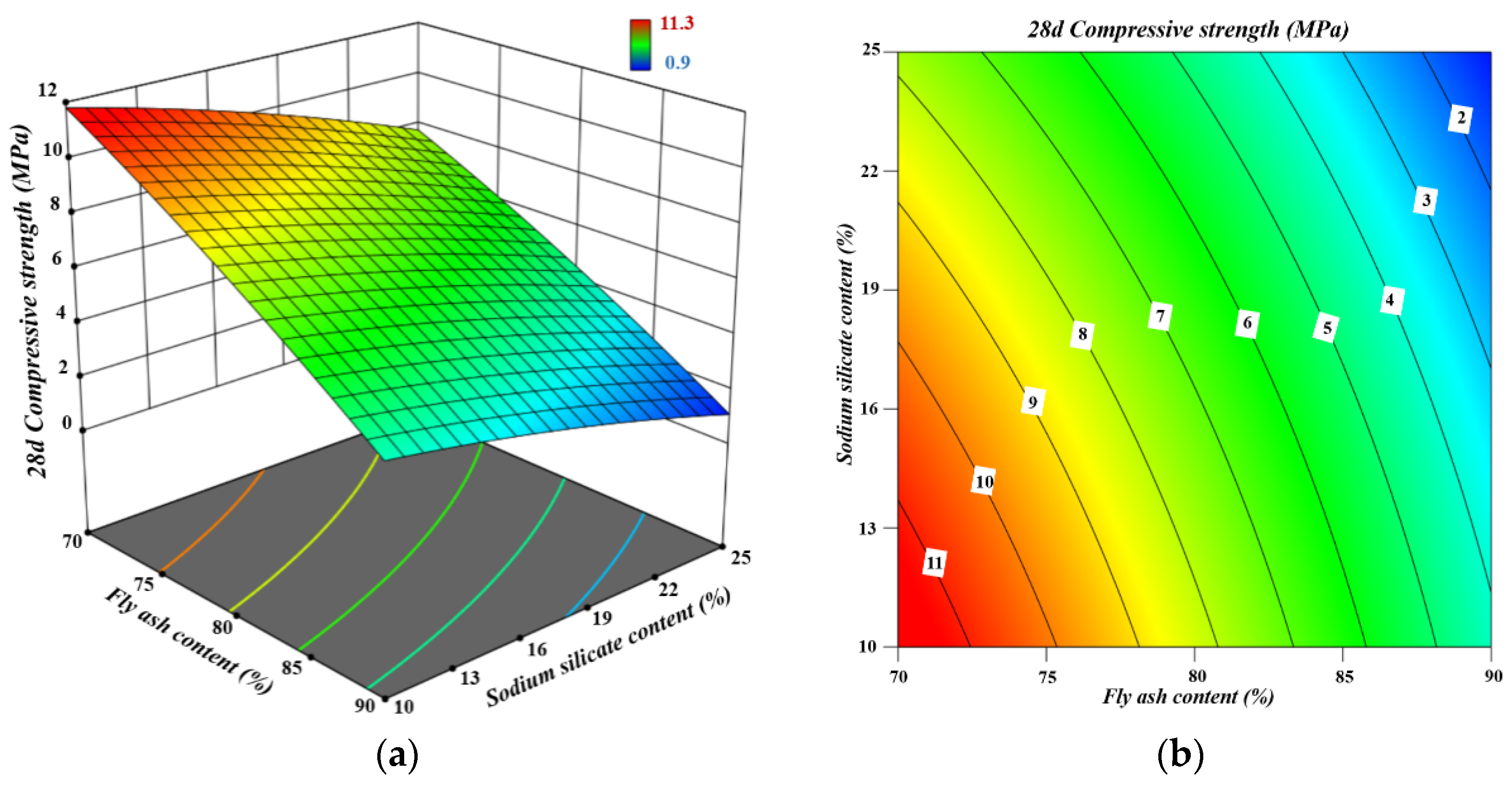
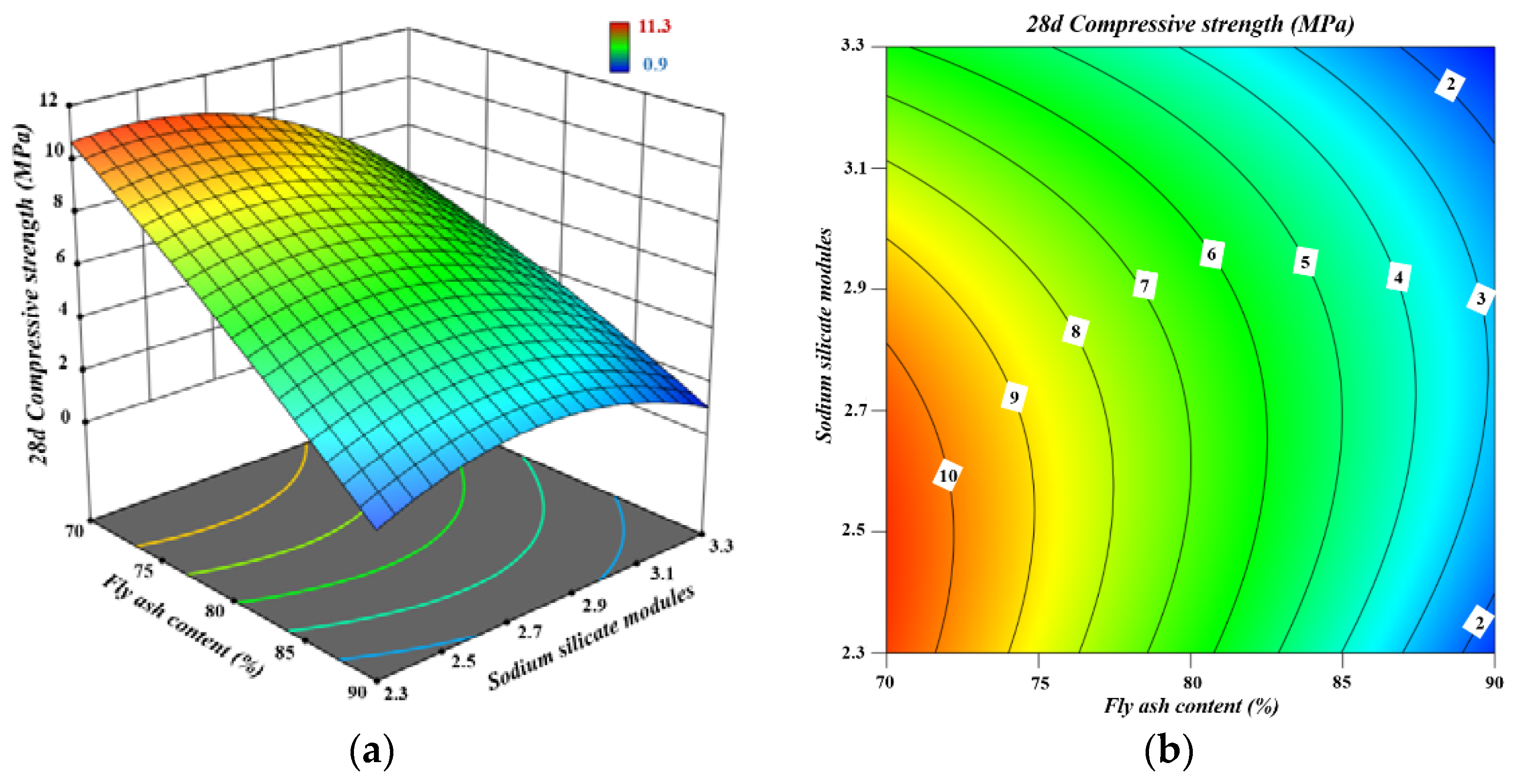
Figure 6 shows the response surface and contour of the 28-day compressive strength of the DLGM mortar under the interaction of sodium silicate content–fly ash content. By fixing the fly ash content, the 28-day compressive strength of the DLGMs mortar shows a decreasing trend with the increase in sodium silicate content (Figure 6a). With a value in the range of 10–25%, the 28-day compressive strength of the DLGM mortar increased with the decrease in fly ash content, and the variation range was large. The response surface changed most significantly when the content of sodium silicate was 10%. Based on the interaction effect of the content of sodium silicate and fly ash on the 28-day compressive strength of the DLGMs mortar, it was clear that when the content of sodium silicate and fly ash was 10–13% and 70–75% respectively, the 28-day compressive strength of the DLGMs mortar was no less than 9.0 MPa (Figure 6b) and could reach up to 11.3 MPa.
Figure 7 shows the response surface and contour of the 28-day compressive strength of the DLGM mortar under the interaction of sodium silicate modulus–fly ash content. When the content of fly ash was fixed, the 28-day compressive strength of the DLGM mortar increased first and then decreased with the increase in the sodium silicate modulus. When the sodium silicate modulus was within the range of 2.3 to 2.6, keeping the constant modulus value, the 28-day compressive strength of the DLGM mortar decreased with the increase in fly ash content. According to the variance analysis of the second-order response surface model (Table 7), it can be seen that the interaction between the sodium silicate content and the sodium silicate modulus has a powerful influence on the strength of the DLGMs mortar (p-value ≤ 0.01). Through the interaction of the sodium silicate modulus and fly ash content, it is clear that to ensure that the 28-day compressive strength of the DLGM mortar was higher than 10.0 MPa; the sodium silicate modulus must be kept within the range of 2.3–2.7, and the fly ash content should be lower than 72% (Figure 7b).
Figure 8 shows the response surface and contour of the 28-day compressive strength of the DLGM mortar under the interaction of sodium silicate modulus–sodium silicate content. When the sodium silicate modulus was fixed, the 28-day compressive strength of the DLGM mortar decreased with the increase in sodium silicate content. When the sodium silicate content was fixed, the 28-day compressive strength increased first and then decreased with the decrease in the sodium silicate modulus. Under the interaction of sodium silicate modulus–sodium silicate content, it is suggested that the sodium silicate modulus and the content should be controlled in the range of 2.50–2.78 and 10–11.8%, respectively, to ensure that the 28-day compressive strength of the DLGM mortar is no less than 8.0 MPa.

4. Composition and Microstructure of Hardened Slurry A and Slurry C

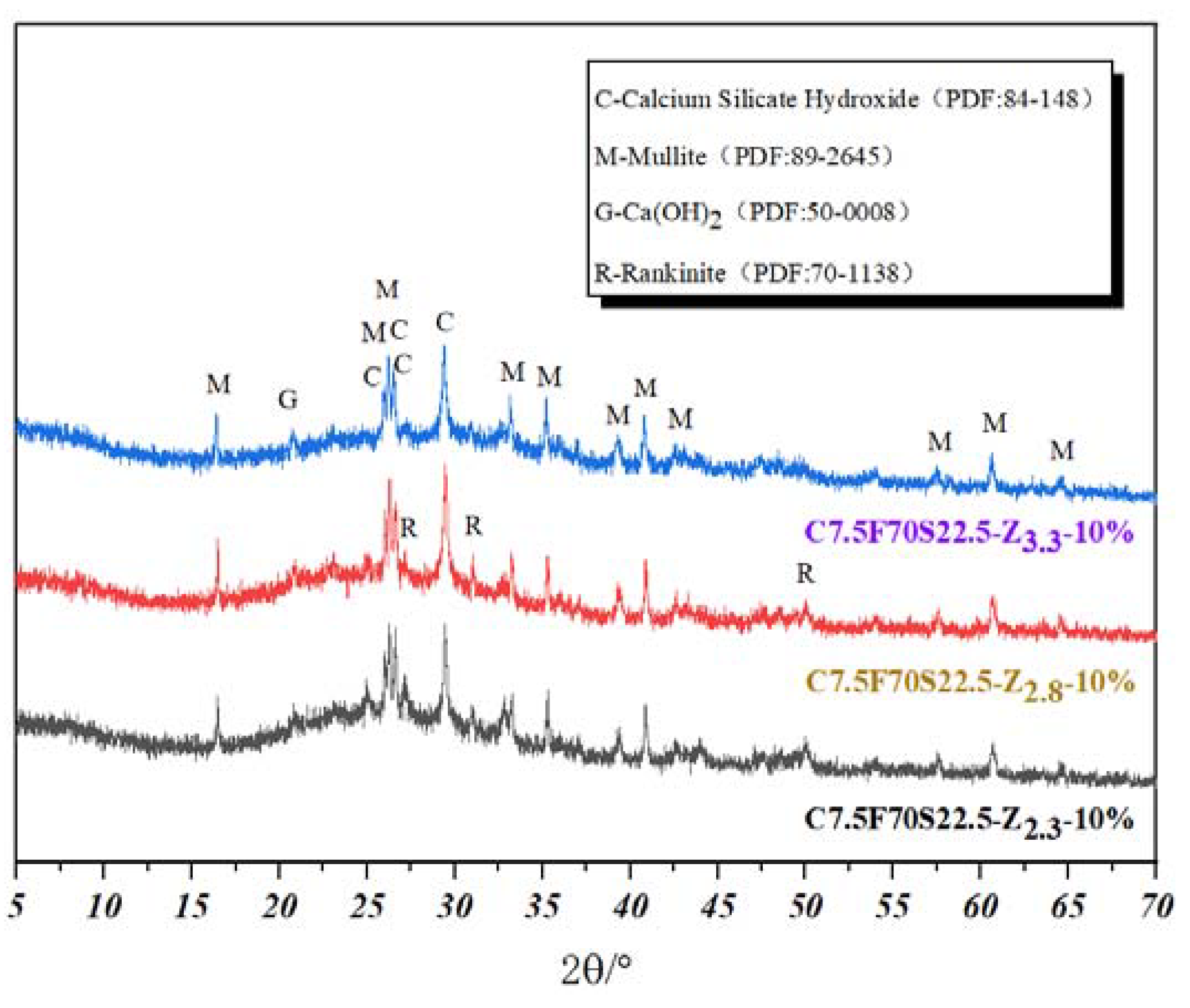
Figure 9 shows the XRD patterns of slurry A at the age of 28 days. The characteristic peak intensity of cement hydration product Ca(OH)2 decreased with the increase in the amount of slag. The results showed that the reactivity of slag was higher, which led to a large consumption of Ca(OH)2 generated from the cement hydration [43,44,45]. Figure 10 shows the XRD patterns of hardened slurry C, prepared with different sodium silicate moduli at the age of 28 days. By changing the sodium silicate modulus, the characteristic peak intensity of Ca(OH)2 was significantly reduced, and amorphous peaks appeared in the range of 20–35°, which might be due to the formation of C-S-H gel in the system. The amorphous peak in the XRD pattern became more visible with the decrease in sodium silicate modulus. The lower modulus of sodium silicate was more conducive to activate the potential reactivity of slag and fly ash, thus promoting the formation of more amorphous substances and easily improving the compressive strength of the DLGM mortar [46].
Figure 11 shows the SEM images of the C7.5F70S22.5 and the C22.5F70S7.5 groups after 28 days of curing. It can be found that there were both geopolymer gel and crystalline hydration products, as well as a few small needle-like crystals. The surface of the fly ash particles suffered uneven corrosion. Compared to the C7.5F70S22.5 group, the C22.5F70S7.5 group contained more flocculated C-S-H gel and hexagonal plate Ca(OH)2 crystals. Figure 12 shows the SEM images of the DLGMs pastes prepared with different sodium silicate moduli at the age of 28 days. After adding sodium silicate to slurry A, the hydration reaction of the cement and the alkali activation reaction would be carried out simultaneously. The C7.5F70S22.5-Z3.3 group had more microcracks, while the C7.5F70S22.5-Z2.3 group and the C7.5F70S22.5-Z2.8 group were denser than the C7.5F70S22.5-Z3.3 group. Compared to the C7.5F70S22.5-Z2.3 group, the distribution of the reaction products was more uniform in the C7.5F70S22.5-Z2.8 group.
Cement hydration in slurry A could produce C-S-H gel and plenty of Ca2+. With the effect of sodium silicate (alkaline stimulator), Ca2+ could react with [SiO4]4- quickly to form C-S-H gel [37,38], and it also promoted the hydration of C3S and C2S in the slurry to form more C-S-H gel. The fly ash and slag were condensed together to enhance the cementitious performance of the grouting materials. Simultaneously, the alkaline environment, provided by the sodium silicate, was also conducive to promoting the fracture of Ca-O, Si-O-Si, and Si-O-Al bonds in slag and fly ash to form monomers, thus forming the network macromolecules through condensation and polymerization [47,48], which accelerated its condensation and hardening and improved the compressive strength of the DLGMs. The reduction of the sodium silicate modulus could provide a strongly alkaline environment for the reactive powder in the grouting material, which promoted the hydration of C3S and C2S minerals in cement, and the chemical bonds of the highly reactive powder were dissolved and reaggregated under the alkali environment [49], making its structure more compact. However, the low sodium silicate modulus would interfere with the synchronicity between the reaction rate of alkali activation and the cement hydration in the DLGMs, thus affecting the uniform distribution of the reaction products.

5. Conclusions

The DLGMs, used for regenerating the roof of a coal mine, were prepared by fly ash, slag, ordinary Portland cement, and sodium silicate. Additionally, the mix design parameters of the DLGMs were optimized as well, based on the response surface method. Furthermore, the formation mechanism of the compositions and the microstructures of the DLGMs were revealed via using XRD and SEM. The main conclusions are drawn as follows:
(1)
Slurry A was prepared with fly ash, slag, and ordinary Portland cement. Compared to the C7.5F70S22.5 group, when the cement content was 7.5%, the operable time and settlement rate of the C7.5F22.5S70 group were reduced by 9.5% and 45.8%, respectively. The viscosity of the C7.5F70S22.5 group was 7.9% lower than that of the C7.5F22.5S70 group. However, compared to the C22.5F70S7.5 group, when the cement content was increased to 22.5%, the operable time and settlement rate of the C22.5F7.5S70 group were reduced by 24.8% and 54.2%, respectively and the viscosity of the C22.5F70S7.5 group was reduced by 18.3% compared to that of the C22.5F7.5S70 group.
(2)
Slurry C acquired a fast setting time by the addition of sodium silicate (slurry B) to slurry A. The relative content of the cement and the sodium silicate modulus was the main factor affecting the operable time of slurry C. Compared to the C30F70S0-Z3.3 group, the operable time of the C0F70S30-Z3.3 group increased by approximately 36 min. Due to the reduction in the modulus of sodium silicate, compared to the C0F70S30-Z3.3 group, the operable time of the C0F70S30-Z2.3 group decreased by 10.6%.
(3)
The design parameters of the DLGMs were optimized based on the response surface method. The regression model and response surface could well reflect the influence of multiple factors on the properties of the DLGMs. When the fly ash content, sodium silicate modulus, and sodium silicate content were 70–75%, 2.3–2.7, and 10–13%, respectively, the properties of the DLGMs were excellent. When the mass percentage of cement, fly ash, and slag in slurry A was 7.5%:70%:22.5%, and the sodium silicate modulus and content in slurry B were 2.8 and 10%, respectively, the 28-day compressive strength of the DLGM mortar could reach up to 11.3 MPa. To obtain higher compressive strength of the DLGMs, it is recommended to choose the ratio above. This is the best ratio for the DLGMs. According to the variance analysis of the response surface model, the influence of the experimental design on the 28-day compressive strength of the DLGM mortar is in the order, from strong to weak, of fly ash content, sodium silicate content, and sodium silicate modulus.
(4)
After mixing different moduli of sodium silicate into the C7.5F70S22.5 group, the characteristic peak intensity of the Ca(OH)2 revealed a significant reduction, and a broader amorphous peak appeared in the range of 20° to 35°. With the decrease in the sodium silicate modulus, the amorphous peak became more obvious, indicating that amorphous phases were produced in the system. The SEM results showed that the microstructure of the C7.5F70S22.5-Z2.3 and the C7.5F70S22.5-Z2.8 groups was denser than that of the C7.5F70S22.5-Z3.3 groups. Compared to the C7.5F70S22.5-Z2.3 group, the distribution of the reaction products in the C7.5F70S22.5-Z2.8 group was more uniform.
In this paper, substantial amounts of fly ash are used as the main raw material to design and prepare a new type of grouting material slurry for regenerating the roof in low-cost mining. It can be applied to reinforce the collapsed rock of the regenerated roof and help to shorten the mining cycle, improving its economic benefits. The compressive strength of the grouting material is not high in the short term due to the limitations of the fly ash raw material; thus, it is not suitable for the reinforcement and seepage prevention in water-enrichment projects.

Author Contributions

Investigation, Z.L., P.L., K.L., G.Y., Q.Z., Y.H. and H.X.; resources, A.W., D.S., G.Y., Q.Z. and Y.H.; writing—original draft preparation, P.L., K.L. and H.X.; writing—review and editing, A.W., Z.L., P.L., K.L., G.Y., Q.Z., Y.H., H.X. and D.S.; funding acquisition, A.W., K.L. and D.S. All authors have read and agreed to the published version of the manuscript.

Funding

The authors are grateful for the financial support from the National Natural Science Foundation of China (52278236, 52172013), the Key Research and Development Projects in Anhui Province (202004b11020033, 202104a07020018), and the Cultivation Project of the Scientific Research Reserve of Anhui Jianzhu University (2021XMK02).

Data Availability Statement

Not applicable.

Conflicts of Interest

The authors declare no conflict of interest.

References

  1. Zhu, C.; Zhang, J.; Li, M.; He, Z.; Wang, Y.; Lan, Y. Effect mechanism of strata breakage evolution on stope deformation in extra-thick coal seams. Alex. Eng. J. 2022, 61, 5003–5020. [Google Scholar] [CrossRef]
  2. Pan, C.; Xia, B.; Zuo, Y.; Yu, B.; Ou, C. Mechanism and control technology of strong ground pressure behaviour induced by high-position hard roofs in extra-thick coal seam mining. Int. J. Min. Sci. Technol. 2022, 32, 499–511. [Google Scholar] [CrossRef]
  3. Lv, H.; Cheng, Z.; Liu, F. Study on the mechanism of a new fully mechanical mining method for extremely thick coal seam. Int. J. Rock Mech. Min. Sci. 2021, 142, 104788. [Google Scholar] [CrossRef]
  4. Liu, H.; Wang, Y.; Pang, S.; Wang, X.; He, J.; Zhang, J.; Rodriguez-Dono, A. Mining footprint of the underground longwall caving extraction method: A case study of a typical industrial coal area in China. J. Hazard. Mater. 2022, 425, 127762. [Google Scholar] [CrossRef]
  5. Çelik, A.; Özçelik, Y. Investigation of the efficiency of longwall top coal caving method applied by forming a face in horizontal thickness of the seam in steeply inclined thick coal seams by using a physical model. Int. J. Rock Mech. Min. Sci. 2021, 148, 104917. [Google Scholar] [CrossRef]
  6. Tu, S.-H.; Yong, Y.; Zhen, Y.; Ma, X.-T.; Qi, W. Research situation and prospect of fully mechanized mining technology in thick coal seams in China. Procedia Earth Planet. Sci. 2009, 1, 35–40. [Google Scholar] [CrossRef] [Green Version]
  7. Pan, D.; Hong, K.; Fu, H.; Zhou, J.; Zhang, N.; Lu, G. Influence characteristics and mechanism of fragmental size of broken coal mass on the injection regularity of silica sol grouting. Constr. Build. Mater. 2021, 269, 121251. [Google Scholar] [CrossRef]
  8. Shimada, H.; Hamanaka, A.; Sasaoka, T.; Matsui, K. Behaviour of grouting material used for floor reinforcement in underground mines. Int. J. Surf. Min. Reclam. Environ. 2014, 28, 133–148. [Google Scholar] [CrossRef]
  9. Cheng, M.-Y.; Hoang, N.-D. Groutability prediction of microfine cement based soil improvement using evolutionary LS-SVM inference model. J. Civ. Eng. Manag. 2014, 20, 839–848. [Google Scholar] [CrossRef]
  10. Hesse, J.C.; Schedel, M.; Diedel, R.; Sass, I. Influence of swelling and non-swelling clays on the thermal properties of grouting materials for borehole heat exchangers. Appl. Clay Sci. 2021, 210, 106154. [Google Scholar] [CrossRef]
  11. Guo, L.; Zhou, M.; Wang, X.; Li, C.; Jia, H. Preparation of coal gangue-slag-fly ash geopolymer grouting materials. Constr. Build. Mater. 2022, 328, 126997. [Google Scholar] [CrossRef]
  12. Xu, C.; Zhang, Z.; Tang, X.; Gui, Z.; Liu, F. Synthesis and characterization of one-part alkali-activated grouting materials based on granulated blast furnace slag, uncalcined coal gangue and microscopic fly ash sinking beads. Constr. Build. Mater. 2022, 345, 128254. [Google Scholar] [CrossRef]
  13. Li, B.; Zhang, J.; Liu, Y.; Qu, L.; Liu, Q.; Sun, Y.; Xu, G. Interfacial porosity model and modification mechanism of broken coal grouting: A theoretical and experimental study. Surf. Interfaces 2022, 33, 102286. [Google Scholar] [CrossRef]
  14. Li, G.; Sun, Y.; Qi, C. Machine learning-based constitutive models for cement-grouted coal specimens under shearing. Int. J. Min. Sci. Technol. 2021, 31, 813–823. [Google Scholar] [CrossRef]
  15. Wu, T.; Gao, Y.; Zhou, Y. Application of a novel grouting material for prereinforcement of shield tunnelling adjacent to existing piles in a soft soil area. Tunn. Undergr. Space Technol. 2022, 128, 104646. [Google Scholar] [CrossRef]
  16. Gao, Y.; Jing, H.; Fu, G.; Zhao, Z.; Shi, X. Studies on combined effects of graphene oxide-fly ash hybrid on the workability, mechanical performance and pore structures of cementitious grouting under high W/C ratio. Constr. Build. Mater. 2021, 281, 122578. [Google Scholar] [CrossRef]
  17. Cui, Y.; Tan, Z.; An, C. Research and application of multi-functional acrylic resin grouting material. Constr. Build. Mater. 2022, 359, 129381. [Google Scholar] [CrossRef]
  18. Thumrongvut, J.; Seangatith, S.; Phetchuay, C.; Suksiripattanapong, C. Comparative experimental study of sustainable reinforced Portland cement concrete and geopolymer concrete beams using rice husk ash. Sustainability 2022, 14, 9856. [Google Scholar] [CrossRef]
  19. Phoo-Ngernkham, T.; Hanjitsuwan, S.; Dethan, S.; Thumrongvut, J.; Suksiripattanapong, C.; Damrongwiriyanupap, N.; Chindaprasirt, P.; Hatanaka, S. Shear bond strength of FA-PC geopoylmer under different sand to binder ratios and sodium hydroxide concentrations. Int. J. Geomate 2018, 42, 52–57. [Google Scholar] [CrossRef]
  20. Jiao, Z.; Li, X.; Yu, Q.; Yao, Q.; Guan, X.; Hu, P. Chloride resistance of class C/class F fly ash-based geopolymer mortars with different strength grades. Case Stud. Constr. Mater. 2023, 18, e01811. [Google Scholar] [CrossRef]
  21. Sun, X.; Liu, H.; Tian, Z.; Ma, Y.; Wang, Z.; Fan, H. Feasibility and economic evaluation of grouting materials containing binary and ternary industrial waste. Constr. Build. Mater. 2021, 274, 122021. [Google Scholar] [CrossRef]
  22. Güllü, H.; Cevik, A.; Al-Ezzi, K.M.; Gülsan, M.E. On the rheology of using geopolymer for grouting: A comparative study with cement-based grout included fly ash and cold bonded fly ash. Constr. Build. Mater. 2019, 196, 594–610. [Google Scholar] [CrossRef]
  23. Jin, J.; Zhang, G.; Qin, Z.; Liu, T.; Shi, J.; Zuo, S. Viscosity enhancement of self-consolidating cement-tailings grout by biomass fly ash vs. chemical admixtures. Constr. Build. Mater. 2022, 340, 127802. [Google Scholar] [CrossRef]
  24. Do, T.M.; Kim, H.-K.; Kim, M.-J.; Kim, Y.-S. Utilization of controlled low strength material (CLSM) as a novel grout for geothermal systems: Laboratory and field experiments. J. Build. Eng. 2020, 29, 101110. [Google Scholar] [CrossRef]
  25. Zhou, Y.; Wang, G.H.; Yuan, Y.F. Basic properties and engineering application of bentonite-cement-water glass grouting. KSCE J. Civ. Eng. 2020, 24, 2742–2750. [Google Scholar] [CrossRef]
  26. Zhang, Y.; Wang, S.; Zhang, B.; Hou, D.; Li, H.; Li, L.; Wang, J.; Lin, C. A preliminary investigation of the properties of potassium magnesium phosphate cement-based grouts mixed with fly ash, water glass and bentonite. Constr. Build. Mater. 2020, 237, 117501. [Google Scholar] [CrossRef]
  27. Sha, F.; Li, S.C.; Lin, C.J.; Liu, R.T.; Zhang, Q.S.; Yang, L.; Li, Z.F. Research on penetration grouting diffusion experiment and reinforcement mechanism for sandy soil porous media. Rock Soil Mech. 2019, 40, 4259–4269. [Google Scholar] [CrossRef]
  28. Lee, J.; Bang, C.; Mok, Y.; Joh, S. Numerical and experimental analysis of penetration grouting in jointed rock masses. Int. J. Rock Mech. Min. Sci. 2000, 37, 1027–1037. [Google Scholar] [CrossRef]
  29. Sha, F.; Li, H.; Pan, D.; Liu, H.; Zhang, X. Development of steel slag composite grouts for underground engineering. J. Mater. Res. Technol. 2020, 9, 2793–2809. [Google Scholar] [CrossRef]
  30. Wang, S.; He, C.; Nie, L.; Zhang, G. Study on the long-term performance of cement-sodium silicate grout and its impact on segment lining structure in synchronous backfill grouting of shield tunnels. Tunn. Undergr. Space Technol. 2019, 92, 103015. [Google Scholar] [CrossRef]
  31. Zhu, Z.; Wang, M.; Liu, R.; Zhang, H.; Zhang, C.; Liu, Y.; Bai, J.; Zhang, L. Study of the viscosity-temperature characteristics of cement-sodium silicate grout considering the time-varying behaviour of viscosity. Constr. Build. Mater. 2021, 306, 124818. [Google Scholar] [CrossRef]
  32. Zhang, C.; Yang, J.; Fu, J.; Wang, S.; Yin, J.; Ou, X.F.; Xie, Y. Optimal formulation design of polymer-modified cement based grouting material for loose deposits. Constr. Build. Mater. 2020, 261, 120513. [Google Scholar] [CrossRef]
  33. JC/T 2536; Cement Sodium Silicate Grout. China Building Materials Press: Beijing, China, 2019. (In Chinese)
  34. GB/T 17671-2020; Standard for Method of Testing Cements-Determination of Strength. People’s Republic of China National Standard. The State Bureau of Quality and Technical Supervision of the People’s Republic of China: Beijing, China, 2020. (In Chinese)
  35. Kumar, S.; Suman, S.K. Investigating the properties of cement grouted bituminous mix with alternative grout compositions. Mater. Today Proc. 2022, 65, 831–838. [Google Scholar] [CrossRef]
  36. Song, B.; Liu, S.; Hu, X.; Ouyang, K.; Li, G.; Shi, C. Compressive strength, water and chloride transport properties of early CO2-cured Portland cement-fly ash-slag ternary mortars. Cem. Concr. Compos. 2022, 134, 104786. [Google Scholar] [CrossRef]
  37. Li, L.; Wei, Y.-J.; Li, Z.; Farooqi, M.U. Rheological and viscoelastic characterizations of fly ash/slag/silica fume-based geopolymer. J. Clean. Prod. 2022, 354, 131629. [Google Scholar] [CrossRef]
  38. Li, L.; Yang, J.; Li, H.; Du, Y. Insights into the microstructure evolution of slag, fly ash and condensed silica fume in blended cement paste. Constr. Build. Mater. 2021, 309, 125044. [Google Scholar] [CrossRef]
  39. Chang, J.J. A study on the setting characteristics of sodium silicate-activated slag pastes. Cem. Concr. Res. 2003, 33, 1005–1011. [Google Scholar] [CrossRef]
  40. Lin, R.; Yang, L.; Pan, G.; Sun, Z.; Li, J. Properties of composite cement-sodium silicate grout mixed with sulphoaluminate cement and slag powder in flowing water. Constr. Build. Mater. 2021, 308, 125040. [Google Scholar] [CrossRef]
  41. Chen, K.; Lin, W.-T.; Liu, W. Microstructures and mechanical properties of sodium-silicate-activated slag/co-fired fly ash cementless composites. J. Clean. Prod. 2020, 277, 124025. [Google Scholar] [CrossRef]
  42. Chen, W.; Li, B.; Wang, J.; Thom, N. Effects of alkali dosage and silicate modulus on autogenous shrinkage of alkali-activated slag cement paste. Cem. Concr. Res. 2021, 141, 106322. [Google Scholar] [CrossRef]
  43. Li, X.; Bizzozero, J.; Hesse, C. Impact of C-S-H seeding on hydration and strength of slag blended cement. Cem. Concr. Res. 2022, 161, 106935. [Google Scholar] [CrossRef]
  44. Bellmann, F.; Stark, J. Activation of blast furnace slag by a new method. Cem. Concr. Res. 2009, 39, 644–650. [Google Scholar] [CrossRef]
  45. Zhang, J.; Sun, G.; Wang, C.; Zhang, Y.; Wang, P.; Yan, N. Activation effects and micro quantitative characterization of high-volume ground granulated blast furnace slag in cement-based composites. Cem. Concr. Compos. 2020, 109, 103556. [Google Scholar] [CrossRef]
  46. Gu, L.; Lv, Q.; Wang, S.; Xiang, J.; Guo, L.; Jiang, J. Effect of sodium silicate on the properties of loess stabilized with alkali-activated fly ash-based. Constr. Build. Mater. 2021, 280, 122515. [Google Scholar] [CrossRef]
  47. Cristelo, N.; Soares, E.; Rosa, I.; Miranda, T.; Oliveira, D.V.; Silva, R.A.; Chaves, A. Rheological properties of alkaline activated fly ash used in jet grouting applications. Constr. Build. Mater. 2013, 48, 925–933. [Google Scholar] [CrossRef] [Green Version]
  48. Li, H.; Xu, F.; Li, B.; Sun, T.; Huang, X.; Zhu, J.; Peng, C.; Lin, J.; Chen, Z. Investigation on mechanical properties of excess-sulfate phosphogypsum slag cement: From experiments to molecular dynamics simulation. Constr. Build. Mater. 2022, 315, 125685. [Google Scholar] [CrossRef]
  49. Kamseu, E.; Alzari, V.; Rosa, R.; Nuvoli, D.; Sanna, D.; Mariani, A.; Leonelli, C. Marble wastes recycling: Design and synthesis of low-temperature calcium silicate hydrate under various CaO:SiO2 ratio and alkalinity. Materialia 2021, 20, 101224. [Google Scholar] [CrossRef]
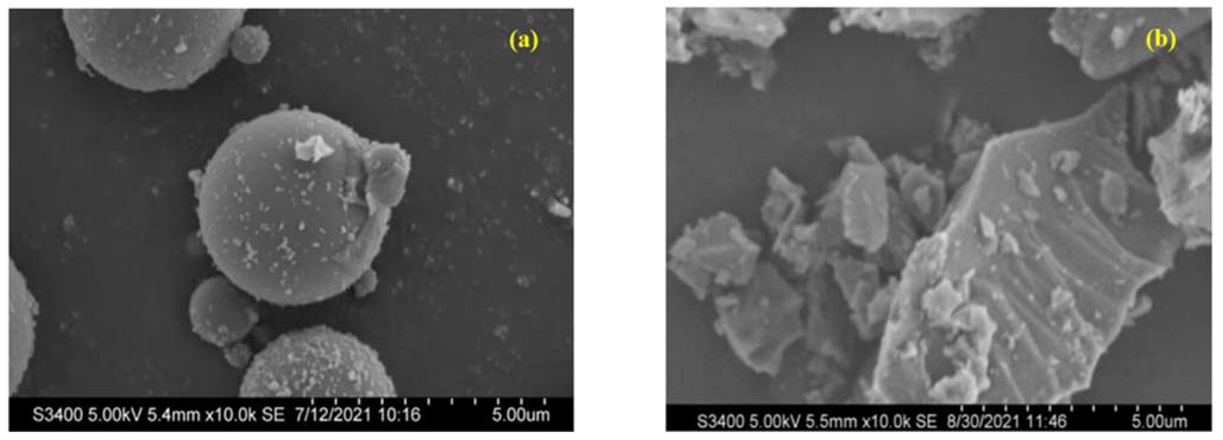
Figure 1. They show the micromorphologies of fly ash (a) and slag (b).
Buildings 13 00584 g001
Figure 2. Effect of raw materials composition on the operable time of slurry A: (a) Effect of cement to slag ratio on the operable time of slurry A. (bd) are the influence of fly ash and slag proportions on the operable time of slurry A at the cement content of 2.5%, 7.5% and 22.5%, respectively.
Buildings 13 00584 g002
Figure 3. Effect of raw material composition on the viscosity of slurry A: (ac) are the effects of fly ash and slag ratio on the viscosity of slurry A when cement content is 2.5%, 7.5% and 22.5%, respectively.
Buildings 13 00584 g003
Figure 4. Effect of raw materials compositions on the stability of slurry A: (ac) are the effects of fly ash and slag ratio on the stability of slurry A when the cement content is 2.5%, 7.5% and 22.5%, respectively.
Buildings 13 00584 g004
Figure 5. Influence of sodium silicate modulus on operation time of slurry C.
Buildings 13 00584 g005
Figure 6. The compressive strength of the DLGM mortar under interaction of sodium silicate content–fly ash content: (a) Response surface; (b) Contour lines.
Buildings 13 00584 g006
Figure 7. The compressive strength of the DLGM mortar under interaction of sodium silicate modulus–fly ash content: (a) Response surface; (b) Contour lines.
Buildings 13 00584 g007
Figure 8. The compressive strength of the DLGM mortar under interaction of sodium silicate modulus sodium–silicate content: (a) Response surface; (b) Contour lines.
Buildings 13 00584 g008
Figure 9. XRD patterns of the slurry A.
Buildings 13 00584 g009
Figure 10. XRD patterns of the DLGMs paste prepared with different sodium silicate moduli.
Buildings 13 00584 g010
Figure 11. SEM images of slurry A: (a) C7.5F70S22.5; (b) C22.5 F70S7.5.
Buildings 13 00584 g011
Figure 12. SEM images of the DLGMs prepared with different sodium silicate moduli: (a) C7.5F70S22.5-Z3.3; (b) C7.5F70S22.5-Z2.8; (c) C7.5F70S22.5-Z2.3.
Buildings 13 00584 g012
Table 1. Chemical compositions of raw materials (wt.%).
Raw MaterialsSiO2Al2O3Fe2O3CaOMgOK2ONa2OSO3TiO2MnOP2O5LOI a
FA52.4529.355.936.690.831.070.890.741.24-0.240.17
SG30.6415.280.3336.885.840.200.350.040.560.24-0.06
CM29.3413.103.2848.671.090.54-3.290.27--0.12
a Note: LOI represents the loss on ignition.
Table 2. Mix ratio of grouting material slurry A.
SeriesCMFASGH2O
C30F70S030700100
C22.5F70S7.522.5707.5100
C15F70S15157015100
C7.5F70S22.57.57022.5100
C0F70S3007030100
C2.5F70S27.52.57027.5100
C2.5F48.75S48.752.548.7548.75100
C2.5F27.5S702.527.570100
C7.5F70S22.57.57022.5100
C7.5F46.25S46.257.546.2546.25100
C7.5F22.5S707.522.570100
C22.5F70S7.522.5707.5100
C22.5F38.75S38.7522.538.7538.75100
C22.5F7.5S7022.57.570100
Table 3. Mix ratio of slurry C.
SeriesSlurry A/kgSlurry B/kg
CMFASGH2O
C30F70S0-ZX3070010066.67
C22.5F70S7.5-ZX22.50707.5010066.67
C15F70S15-ZX15701510066.67
C7.5F70S22.5-ZX7.507022.5010066.67
C0F70S30-ZX0703010066.67
Table 4. Box–Behnken test design with three factors and three levels.
FactorLever
−101
X708090
Y1017.525
Z2.32.83.3
Table 5. Design scheme of response surface analysis test.
GroupXYZGroupXYZ
R18017.52.8R1090102.8
R29017.53.3R1180103.3
R380252.3R128017.52.8
R470102.8R138017.52.8
R57017.52.3R1490252.8
R68017.52.8R1580102.3
R78017.52.8R169017.52.3
R880253.3R177017.53.3
R970252.8
Table 6. The 28-day compressive strength of the DLGMs mortar.
No.28-day Compressive Strength (MPa)No.28-day Compressive Strength (MPa)
R17.2R103.8
R20.9R116.2
R34.0R126.8
R411.3R136.5
R510.8R141.6
R66.9R158.0
R76.5R161.5
R81.3R176.1
R98.2
Table 7. Variance analysis of the second-order response surface model.
SourceF-Valuep-Value
Model58.96<0.0001
X346.09<0.0001
Y85.32<0.0001
Z40.640.0004
XY0.68540.4350
XZ14.230.0070
YZ0.68540.4350
X21.300.2910
Y20.90870.3722
Z238.920.0004
Lack of Fit6.590.0500
R20.9870
Disclaimer/Publisher’s Note: The statements, opinions and data contained in all publications are solely those of the individual author(s) and contributor(s) and not of MDPI and/or the editor(s). MDPI and/or the editor(s) disclaim responsibility for any injury to people or property resulting from any ideas, methods, instructions or products referred to in the content.