Abstract
The design and production of prefabricated buildings pose challenges in achieving standardization, limiting their extensive adoption. In order to address issues of prefabricated components, such as the low reusability of design knowledge, limited standardization, and design disconnection, this paper adopted the prefabricated cantilevered structure components as the research object. It employs knowledge-based engineering (KBE) theory and secondary split modularization approach in conjunction with Revit secondary development technology to establish a modular design system. The system formalizes complex design knowledge into concise user interfaces and a logically clear programming language, ensuring the design system’s ease of use and accessibility. To validate the authenticity and applicability of the modular design system developed in this paper, a comparison is made between the traditional modeling tool and modular modeling tool. Through empirical analysis, the result indicates that the new tool proposed in this paper can enhance the efficiency of design professionals by 72.92%. Among these, the tool meets the modeling and design requirements of 96.1% of the prefabricated components in the project, making it highly suitable for the modeling and design process of the vast majority of prefabricated components. Therefore, this design approach, which integrates KBE and three-dimensional geometric technology, makes the modular design of prefabricated cantilevered structural components feasible, providing a reference for future research in the design of other prefabricated components.
1. Introduction
With the ongoing development of the construction industry, on-site construction methods are gradually leading to off-site manufacturing and off-site construction, offering a fresh perspective for sustainable growth in the construction sector [1]. In comparison to traditional construction, prefabricated buildings exhibit distinct advantages, including cost-effective labor, shortened project timelines, improved resource and energy efficiency, and heightened project quality assurance [2,3,4,5]. This issue has resulted in a gradual increase in their prominence within new construction projects. Nevertheless, the standardization of design and production in prefabricated construction remains relatively low, and design efficiency falls short of meeting the requirements for industrialized construction [6]. Therefore, enhancing the design efficiency and quality of prefabricated buildings is indispensable.
As a critical element in assembly construction, prefabricated components play a significant role throughout the various stages of assembly construction, including design, production, transportation, and construction [7,8]. These components are manufactured in factories according to design specifications and then transported to the construction site for assembly, ultimately achieving the assembly of the target components [9]. With the ongoing advancement of construction industrialization, the demand for the batch design and modification of prefabricated components increases; thus, designers introduced modular design methods, which is progressively emerging as a prominent trend [10,11,12]. Many scholars have adhered to the principles of the humanized design concept, in which various functional modules can be freely combined, leading to diverse and optimized designs of functional spaces. In turn, the time of product replacement and maintenance is shortened, and the consistency and quality of modeling are improved [11]. Therefore, the modular design of residential buildings is particularly important, which can improve the efficiency and quality of building design. At present, prefabricated construction is divided into various prefabricated components, such as walls, beams, slabs, and columns, and each of them undergoes modular design. However, this approach remains at the overall design level of prefabricated components and does not provide further detailed disassembly, which can result in inflexible design changes for the components [13]. Therefore, the modular design for components is of paramount importance, and it should consider various factors to ensure the smooth operation of subsequent projects.
For the modular design of prefabricated components, the rationality of module splitting and standardization becomes crucial. Integrating design standards into module design and leveraging structural databases allow for the acquisition of the optimal approach to modular design [14]. For instance, determining module design dimensions based on module production and installation processes can enhance the universality of module components [15]. By using a construction method based on steel structural module connections, establishing a simplified finite element model for global modular connections facilitates predictive simulation research on the mechanics of components [16]. To address complex engineering design problems involving multiple variables and conditions, it is possible to organically combine design, production, and construction, parameterizing the concrete and rebar modules of prefabricated components separately [17]. Cantilevered elements are commonly modeled by beams and plates. For the modeling and mechanical analysis of these elements, particularly their vibrations, classical and shear deformable beam and plate theories can be utilized [18,19,20,21,22]. In the context of remote manufacturing, ensuring the multi-dimensional consistency of product modularity and construction process modularity [23] can enhance the digitalization level of prefabricated components. Industrialized construction means that the construction industry needs to continuously learn from other fields, such as introducing the DFMA concept from the manufacturing industry. This can help to mitigate challenges in the construction industry, such as low process efficiency and component standardization [24]. Li et al. [25] proposed an intelligent layout method for rebar modules based on DFMA, addressing construction phase requirements during the design phase to enhance rebar construction efficiency and reduce unnecessary costs.
In the realm of prefabricated construction, each phase of design, production, and construction is intricately guided by specialized knowledge, which results in construction enterprises amassing extensive design blueprints and construction experience. However, these knowledge-intensive enterprises often struggle to fully utilize their existing design knowledge [25,26]. To address this, the concept of knowledge-based engineering (KBE) is introduced into the component design process [27]. Feigenbaum [28] first articulated the direction of KBE, which involves acquiring and organizing knowledge from different sources and efficiently managing it, subsequently transforming it into computerized intelligent processing programs. As a product of the intersection development of computer-aided design (CAD) and computer programming disciplines [29], KBE serves as the theoretical foundation for the development of specialized software tools. These tools aim to achieve the reuse of engineering knowledge related to products and processes, ultimately enhancing product design efficiency and reducing product development costs [30]. To implement KBE systems effectively, it is essential to integrate suitable programming methods, establish a clear understanding of the relationships between problems, and achieve the generation of rule-driven models [31].
Many scholars have proposed knowledge reuse models based on CAD/CAE (i.e., KBE technology) [27,30,32,33], demonstrating that KBE can facilitate a rapid product design and support parametric design for complex products. For instance, Corallo et al. [34] applied KBE in the design of aircraft gear shafts, significantly improving design efficiency and reducing research and development costs. By integrating knowledge and information resources, merging physical production with knowledge production, the level of product intelligence continues to rise, pushing society from the industrialization phase into the intelligent phase. Li et al. [35] introduced KBE technology to load the parameters, design experience, and rules of the target product into the model program, enabling innovative design and knowledge reuse. Gembarski et al. [36], using the KBE modeling paradigm of computer-aided design (CAD) systems, achieved a rapid design and customized production by establishing parametric models, defining design rules and automating the generation of design. Chen et al. [37] proposed the concept and architecture of a mechanical product rapid design platform based on modular design and knowledge engineering. They discussed key technologies, including computer-aided modular design techniques and the construction of specific product rapid development systems based on KBE. KBE theory is capable of meeting high repeatability, restrictiveness, and rule-based requirements [38]. At present, KBE is primarily applied in the field of mechanics. To expand its horizons in the construction field, this paper explores the effectiveness of KBE in its application in this field.
This paper focuses on the research of complex prefabricated cantilevered structural components. It employs KBE theory and integrates secondary split modularization methods. Using the Revit development platform and object-oriented knowledge expression techniques, a modular design tool for prefabricated components is developed. By analyzing the design challenges of cantilever structural components, constraints and design rules are examined and summarized. Subsequently, Visual Studio programming tools are utilized to create Winform application windows. Finally, design rules are codified using the C# programming language, enhancing the precision of modeling for prefabricated cantilever structural components.
2. Problem Description
2.1. Classification of Prefabricated Cantilevered Structural Components
The prefabricated building comprises a multitude of prefabricated components, which are manufactured by the factory based on design drawings and transported to the construction site for assembly. With the advancement of the construction industry and the emergence of prefabricated buildings, there has been an increasing utilization of prefabricated components, which plays a crucial role in China’s large-scale urban construction. Therefore, enhancing the design efficiency and precision of these components is an urgent issue that needs to be addressed. In residential buildings, cantilevered structural members differ from conventional internal and external walls as well as structural columns since they serve as load-bearing elements utilizing cable structures or other cantilevered structures. Cantilevered structural components typically exhibit complex shapes and diverse types. Table 1 illustrates several common component types.

Table 1.
Main classifications of cantilevered structural components.
2.2. Challenges in the Design of Prefabricated Cantilevered Structural Components
Common 3D design software, such as Autodesk Revit 2016, does not include an independent design module for cantilever structural components. There are two conventional design methods for such components: one is to draw the outline based on sketches, using stair or floor sketches to outline the component; the other is to create the outline based on families, using functions like extrusion, sweep, and cut to complete the component’s outline. Finally, the reinforcement is modeled at the corresponding locations using the Rebar creation option. Nevertheless, when modeling using the above methods, the following issues arise:
- Complex component information
Cantilever structural components have unique shapes that cannot be defined using standard rectangular or circular parameters. Additionally, designers need to specify the component’s structural settings, such as the diameter of the reinforcement and the layout rules. These layout rules for the same type of reinforcement vary in different locations within the component. The complexity of the component’s shape and the reinforcement leads to a multitude of control parameters and challenging definitions in component design.
- Poor modeling accuracy
Even though commonly used 3D design software provides the “Reinforcement” feature for parameterized reinforcement layout, poor modeling accuracy occurs. However, this functionality is fundamentally based on sketch shapes to create objects. During the definition process of this functionality, constraints related to the dimensions of the rebar template, boundary directions, locking status, and the plane where the sketch is located impose limitations. This leads to non-unique solutions in generating reinforcement within the profile of the target component, often resulting in failures and inaccuracies in rebar modeling.
- Low efficiency in modifications
The low parameter correlation between sketches in different frameworks makes it impossible to perform batch modifications on the same component. For instance, when adjusting the outline of a component model individually, it is necessary to open and edit the outline sketch. After completing the interaction, the related structural diagrams do not sync with the changes, requiring manual adjustments by designers. This not only increases the operational burden on designers but also introduces the risk of errors in other components.
In summary, when creating cantilevered structural components in 3D design software, the following optimizations can be implemented: (1) Discretize components into simple elements; analyze and organize the parameters of these elements; and independently design each element to provide them with adaptive parametric deformability. (2) Define steel reinforcement boundary conditions and size constraints rationally to enhance the robustness during modeling. (3) Establish linkage relationships between elements to simplify the user logic and improve modification efficiency for designers.
3. Research Methodology
Guided by the principles of KBE, this paper embarked on the modular design of cantilevered structural components. The modules were subjected to a secondary split modularization. Subsequently, via secondary development within Revit, employing object-oriented knowledge representation, a responsive modular design system for cantilever structural components was established. This system addresses design challenges associated with cantilevered components, ultimately improving the design efficiency of professionals. The design flowchart is illustrated in Figure 1.
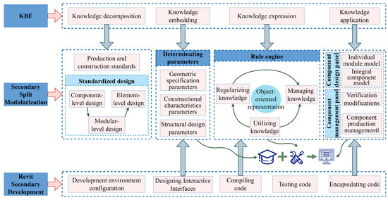
Figure 1.
Flowchart for the KBE-based modular design of components.
3.1. The Theoretical Foundation of KBE
KBE is an engineering design system driven by design knowledge and technology. Through the establishment of computer-aided design (CAD) systems or product information management systems, KBE aims to improve the efficiency of product design by means of knowledge exploration, propagation, representation, inheritance, and management [39]. At the core of KBE lies the tenet of knowledge reuse, manifesting its pervasive applications across the spectrum of engineering product design and manufacturing [30]. Knowledge decomposition and representation serve as essential techniques in the implementation of knowledge engineering systems. Accurate knowledge decomposition results and appropriate knowledge representation methods enable the smooth resolution of complex problems. The process of building a KBE system is illustrated in Figure 2.
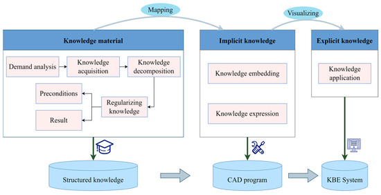
Figure 2.
KBE technical route.
3.2. Secondary Split Modularization
In the prefabricated components of residential buildings, they can be initially divided into vertically stressed components, bent stressed components, cantilevered stressed components, and non-stressed components based on the structural load patterns. This process is referred to as primary split design. Subsequently, the components after primary split are subjected to standardized design. At present, there are two main methods for achieving component standardization: component-level design and element-level design. Component-level design refers to the typification of architectural components and the coordination of modulars. It first classifies the building into prefabricated internal walls, prefabricated external walls, prefabricated composite panels, prefabricated balcony slabs, and prefabricated bay windows, among other categories. Then, it standardizes their dimensions by establishing reasonable component sizes and standards, adhering to the design principle of “few specifications, multiple combinations” [40]. Element-level design focuses on standardizing reinforcing cages and making molds more universal. By reducing the variety of rebar cages to increase the versatility of reinforcement, production costs can be reduced. Through the combination of component-level and element-level design methods, the degree of component standardization can be improved, enabling the regulated and controllable manufacturing of building components within a factory. However, the primary split and its standardization method is only applicable to prefabricated components with simple structural configurations. For components with diverse designs, it fails to meet the requirements. For instance, after a primary split, cantilevered structural components may exhibit issues such as lower overall design level, safety concerns, and insufficient standardization.
Therefore, this paper introduces a module-level standardization approach. It applied a secondary split modularization of components in a “component-level to module-level to element-level” workflow. Components are broken down into multiple modules, each with separately defined design parameters related to geometry, structure, and construction characteristics, and independently modeling each module as individual units. Subsequently, through the interrelated combination of modules, a refined design of the target component is achieved. In addition to addressing design front-end issues, the disassembly process should also involve understanding factory production requirements and collecting feedback from on-site construction. For instance, when standardizing the rebar layout rules within components, it is essential to adhere to modular and standardization principles oriented towards manufacturing and assembly. This approach ensures that the results of secondary split are more reasonable and minimizes excessive design alterations. The manufacturing DFMA theory aims to maximize the design rationality through the targeted research and development of the subsequent manufacturing and assembly process in the product design stage. DFMA includes two parts: Design for Manufacturing (DFM) and Design for Assembly (DFA), which respectively require product design to be integrated with knowledge and experience of manufacturing and assembly processes. Thus, the product has excellent manufacturability and assemblability. Figure 3 illustrates the application of the secondary split modularization design approach in the various phases of design, production, and construction. Tailoring the rebar projecting forms, anchoring methods, and overlay sequences for each module are conducted in response to production and assembly requirements, as well as relevant standards and regulatory knowledge. This ensures the refined and standardized design of each module.
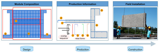
Figure 3.
Secondary split modularization for design–production–construction.
For the secondary split modularization of cantilevered structural components, adherence to modular segmentation principles is essential to meet production and construction requirements, thereby reducing barriers between design and production. Table 2 presents the outcomes of the secondary split for cantilevered structural components, including balcony boards, air conditioning boards, and bay windows.
Table 2.
Results of the secondary split modularization of cantilevered structural components.
3.3. Revit Secondary Development Revit
The 2016 version of Revit is a computer-aided design software for three-dimensional engineering design. It performs tasks such as digital modeling, calculations, drawing, and information management using computers, enabling the intelligent design and visual representation of architectural projects. Additionally, it is one of the primary avenues for modular component design. However, with the recent diversification in architectural forms, Revit may not meet the design needs of all components. Therefore, this paper focuses on the secondary development of Revit to expand its functionality and further enhance component design efficiency.
3.3.1. Development Platform and Workflow
Developing the relevant features on the Revit platform entails utilizing Revit’s Application Programming Interface (API) and Software Development Kit (SDK), which allows for the establishment of connections between input conditions, geometric expressions, and model output. For the secondary development of Autodesk, the C# programming language is the most suitable choice. Therefore, prior to commencing development, it is essential to install the 2016 version of Revit, the 2016 version of SDK and the 2017 version of Visual Studio (VS). In VS, the .NET class library or .NET console application project were created, and then added references in the integrated development environment, including the “Revit API.dll” and “Revit APIUI.dll” assemblies. The development process involves utilizing the object-oriented C# language within the API for plugin development. Subsequently, these plugins are compiled and integrated into Revit for testing purposes. Following the design and modeling steps of prefabricated components, the knowledge expression phase, which involves the development of modular design tools for cantilever structural components, was carried out. During the compilation process, developers have the flexibility to incorporate applications through the external command interface available in the API. For instance, the IExternalCommand interface provides the capability to extend development within its execution function, Execute. Additional auxiliary functions can be integrated here. It is crucial to employ Transaction transactions when conducting changes within the Revit model. All operations that modify the model must occur within an open transaction to avoid exceptions being raised by Revit. Figure 4 illustrates the flowchart of Revit secondary development.
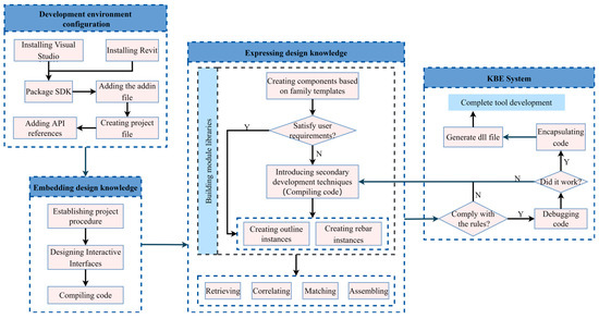
Figure 4.
Flowchart of Revit secondary development.
3.3.2. Development Process for Design Tools
Based on the UI (user interface) design functionality within the Revit software, the IExternalApplication interface and Ribbon controls were utilized to identify and load external plugins through the .addin file. This extends and enhances standalone Revit functionalities. The IExternalApplication interface needs to implement two abstract functions: “OnStartup” and “OnShutdown”. As shown in Formula (1), designers input the program language in the compilation area, bind buttons and backend processes, and then override the two abstract functions To, ultimately, automatically respond to the relevant user commands to accomplish the desired functionalities. The functional panel mainly consists of three parts: modular design, checks and calculations, and component management, as depicted in Figure 5.
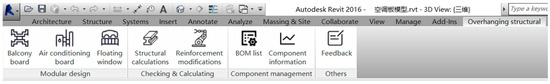
Figure 5.
Function panel.
- User Interface Design
In this paper, WinForm technology was employed for the development of the user interface (UI) to enhance user readability and usability. The parameters of cantilevered structural components were systematically categorized and presented to users through a graphical interface. After embedding knowledge into the model, the model’s dependence on 2D CAD drawings for design was eliminated, and it gained robust adaptability to changes. The user interface design for cantilever structural components can be observed in Figure 6.
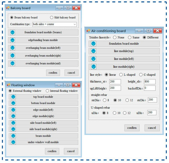
Figure 6.
Interactive interface design for cantilevered structural components.
In this section, the pivotal code concept was as follows:
- Configure the main windows. The main windows were named as the components after the first split. These various component types were indicated by “RadioButtons”. For example, “RadioButton1.Text” was set as “Beam balcony board,” and “RadioButton2.Text” was set as “Slab balcony board”.
- Configure sub-windows. The sub-windows were named as the components after the secondary split. The sub-windows were created using a “FlowLayoutPanel”, forming docked windows that can be collapsed or hidden within their corresponding main window. In the sub-window interface’s dropdown menu, “RadioButton”, “ComboBox”, “Label”, and “TextBox” were utilized for embedding knowledge parameters. By using the appropriate knowledge engineering components, these were linked to bind the corresponding module design parameters. For example, in the dropdown menu of the right-line module in the air conditioning board, “RadioButton” was used to indicate line style types and rebar diameters. “Label” and “TextBox” were used to represent module outline parameters and rebar spacing.
- Configure the confirm and cancel buttons. The “Confirm” and “Cancel” functions were both configured using “Button”. When the user initiated the “Confirm” button click event, the program automatically checked for input errors in the UI. If the input of necessary modules or related design parameters is missing, the program will prompt an error and automatically cancel the operation. If no such problem exists, the procedure will continue. When the user initiates a “Cancel” click event, the program will immediately terminate without making any judgment.
- Creating module libraries for prefabricated cantilevered structures
The module library of the prefabricated cantilevered structure was implemented based on data linkage between the UI interface and design rules, as depicted in Figure 7. The rules’ engine is formed by computer program logic, formalizing and conditioning knowledge-decomposition-derived rules for balcony board reinforcement anchorage forms, so that the program can automatically process user input data according to predefined rules. This completes the required part modeling and forms a standardized module library after verification to avoid redundant modeling and improve module design efficiency. The following details describe the design and development process of cantilevered structural components:
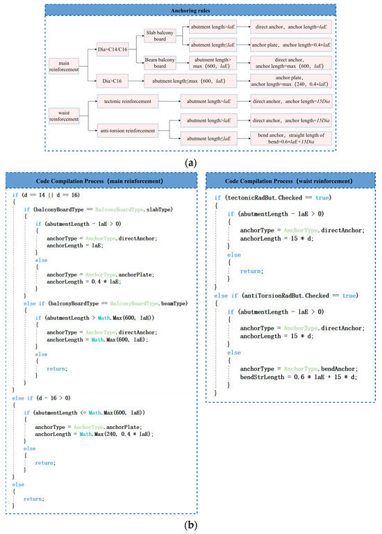
Figure 7.
Conditionalization of the design rules. (a) Anchoring rules; (b) code compilation process.
- Generate contour family examples of prefabricated cantilevered structures
The program’s fundamental concept for generating the instantiation family is to utilize Revit’s external family functions to create instances of various contour and rebar types, while setting relevant design parameters. As depicted in Figure 8, the figure illustrates the outline model of the C-Shape line module within the air conditioning board member. Depending on the location of the contour family file, it is loaded into the code compilation document using the “LoadFamily” function.
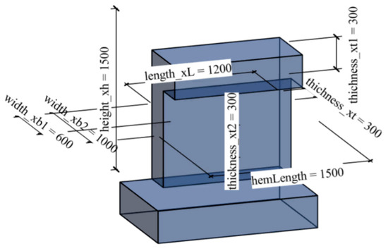
Figure 8.
Model of the C-shaped line modules.
A collector of family types is created, filtering for the target contour family type “FamilySymbol” and instantiating the family type through the “Create.newFamilyInstance” function to obtain “FamilyInstance”. In this scenario, parameter values need modification to accomplish the parametric design of the desired product. Among them, for instance, the length in the line module can be automatically matched with the foundation board module’s length or width during the compilation process by enabling data binding. Other design parameters need to be bound based on user input from UI. For example, Formula (2) modifies the length value in the C-shape line module and Formulas (3) and (4) modify its height value:
- 2.
- Rebar arrangement for prefabricated cantilevered structural modules
The basic idea behind creating rebar involves dividing areas according to rebar positions in models and utilizing API’s “Line.create()” function to establish positioning lines. Subsequently obtaining “PlanarFace” of steel bar allows arranging rebar based on rebar instance, positioning lines, and contour surface using the “Create.NewFamilyInstance” instantiation method. Taking C-shaped line as an example, the respective positioning lines were calculated for each rebar segment with the spatial layout shown in Figure 9.
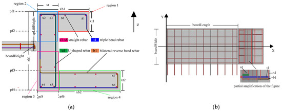
Figure 9.
Schematic diagram of the rebar position in the C-shaped module. (a) Front view layout of rebars; (b) Top view layout of rebar.
We calculated the angle bar positioning line of the straight rebar. The line module was divided into four regions (region1–region4). The length, width, and height of the foundation board were boardLength, boardWidth, and boardHeight respectively. The coordinates of the foundation board were (XBoard, Yboard, and Zboard). We calculated the positioning line of the s1–s8 straight rebar. The layout spacing of the straight rebar was strDis. The thickness of the protective layer was protLayerThickness and the diameter of triple bend rebar was triDia. The U-shaped rebar was uDia in diameter and the bilateral reverse bend rebar was biRevDia in diameter. The formula for calculating the positioning line of the s1 rebar in the figure is as follows:
The start coordinates of s1, named sStartPt:
The end coordinates of s1, named sEndPt:
The positioning line of s1, named sLoc:
The rebar was generated based on the line outline to form a horizontal plane. Specifically, using the “Create.NewFamilyInstance” method, s1 was generated based on the pf1 plane shown in the above figure. Similarly, the positioning lines for the straight rebars s2–s7 were obtained and the corresponding reinforcement examples were generated according to different pf surfaces. The offset method was used to generate the corresponding rebar positioning line based on the spacing of rebars. The formula for calculating the positioning line of s8, named eigLoc, is as follow:
The same method can be applied to calculate the positioning lines for other straight bars. However, if the user enters a line outline size parameter that is too small, resulting in an X direction lower than one strDis distance in region1, the no.8 straight rebar will not be generated. Similarly, if n strDises satisfies the distance requirement, n intermediate straight rebars will be generated.
Triple bend rebar, U-shaped rebar, and bilateral reverse bend rebar do not require zone division. Therefore, this step was omitted. However, due to their complex shapes, different methods were used to create steel bar families, which result in different layouts for these steel bars. As shown in the above figure, a triple bend rebar was created based on the pf5 of the line outline; the U-shaped rebar was created based on the pf6 of the line outline; and the bilateral reverse bend rebar was created based on the pf3 of the line outline. The starting point and end point coordinates for t1, u1, and b1 were calculated as follows:
The start coordinates of t1, named tStartPt:
The end coordinates of t1, named tEndPt:
The start coordinate of u1, named uStartPt:
The end coordinate of u1, named uEndPt:
The start coordinate of b1, named bStartPt:
The end coordinate of b1, named bEndPt:
The method for calculating the positioning line of the steel bar is identical to that of the straight steel bar. Therefore, we utilized the same approach to create instances of steel bars t1, u1, and b1. For other reinforcement positions, based on user input regarding corresponding reinforcement arrangement spacing, we employed the “ElementTransformUtils.CopyElement” function in the API.
This paper employed the aforementioned method to elucidate both a contour of the C-shaped line module and how to generate steel bars within air conditioning boards. Similarly, modules required by balcony boards and bay windows were obtained using this same methodology. To avoid repetitive operations, the relevant generated code was encapsulated during compilation so as to independently create unit components and achieve design knowledge reuse. The reason behind utilizing packaging methods lies in strengthening the correlations between the parts while eliminating multiple compilations. Thus, the convenient invocation of these methods is facilitated by developers at any time for improved modeling efficiency. Finally, design information, such as Building Information Modeling (BIM) models and compiled code for each module, is stored within a module library that forms a comprehensive collection of cantilevered structural component modules.
- Assembly design of prefabricated cantilevered structure components
According to user input information in UI, the modular design of cantilevering structure components was completed by using the functions of data association, model matching, code fetching, and model combination of module library. In addition to completing basic component modeling tasks, examples of embedded parts can also be retrieved from auxiliary module libraries enabling more detailed designs for target components. Figure 10 illustrates an example of a combination process involving specific types of air conditioning board components integrated with L-shape lines.
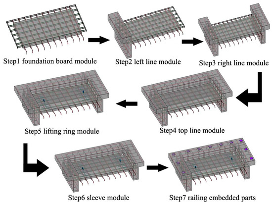
Figure 10.
Modular combination process for an air conditioning board.
- Function for verification and modification
After creating the necessary component models, it was essential to perform structural design checks and verify whether the modules meet the requirements for design and production. This verification process helped to identify areas that may require necessary modifications.
The pivotal code concept for structural verification was as follows: ① Read the component parameters. Created a “Read” method to extract the original cross-sectional data of the model, retrieving data from “TextBox.Text” or “RadioButton” inputs. ② Perform formula-based calculations. The acquired data were input into the calculation formulas to carry out load calculations and execute subroutines.
The pivotal code concept for modifying the model’s rebars was as follows: ① Identify the targeted rebar type. By comparing the rebar type and distribution information before and after modification, identify the rebar number to be modified. ② Remove rebar instances. Used the rebar number as a reference to acquire the corresponding rebar “ElementId” and then employ the “Delete” method to remove the rebar instance. ③ Reposition new rebars. Based on the new rebar information input, utilize the encapsulated “Create.NewFamilyInstance” method to regenerate the rebars.
- Function for component management
The function mainly consists of two parts: bill of materials (BOM) and component information. Among them, BOM is a document that explains the structure of the product, showing the structural relationship between the final assembly, sub-assembly, components, components, parts, and raw materials of the component in the form of a chart, as well as the required quantity. For the assembled components, the BOM list is mainly manifested as the steel bar bill of materials. The prefabricated BOM list is a very important link in industrial manufacturing. It can help factories to assemble products correctly in a short time and improve production efficiency.
To facilitate production and construction management and enhance the connection between design and construction, component information, rebar information, and concrete information were all stored in a “Dictionary”. The pivotal code concept was as follows: ① Module information was saved on-the-fly. Create a “Write” method to input the required instance information and add it to the extended storage “GUID”. ② Describe the stored entities. Use the “Schema” and “Entity” methods to identify the objects within the “GUID”. ③ Transfer and access data. Use the “JsonConvert” method to display the entity data in the corresponding data format, and then store these data in a dictionary. Finally, used the “Dataview” method to bind data and assign functionality, allowing access to data information in component management.
4. Case Study
4.1. Case Overview
The project falls under the category of prefabricated residential construction and is located in the Qing Shan district of Wuhan, with a total floor area of approximately 197,920 square meters and a capacity building area of 142,000 square meters. The project primarily consists of residential buildings, with a small number of ground-floor businesses, supporting facilities, and one kindergarten. It includes one 16-story building, six 18-story small high-rise buildings, and two 45-story super-high-rise residential buildings, all of which utilize a shear wall structural system. The project is a hybrid construction, combining prefabricated components and cast-in-place columns. The types of prefabricated components used include precast shear walls, precast infill walls, precast composite slabs, precast stairs, precast balcony boards, precast air conditioning boards, and precast bay windows. The prefabrication rate reaches 46% based on the capacity building area. Among these prefabricated components, cantilevered structural components make up 12% of the project.
4.2. Model Establishment and Management
The modular design tool for cantilevered structural components, based on KBE, developed in this paper was applied to this practical case. The generated design model is shown in Figure 11, with the orange blocks representing the prefabricated balcony board components, the yellow blocks representing the prefabricated air conditioning board components, and the red blocks representing the prefabricated bay window components.
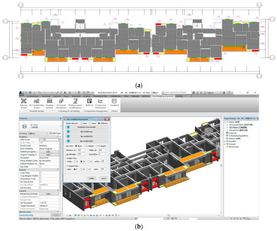
Figure 11.
Result of components’ modeling. (a) Site plan; (b) 3D design model.
Using the “Reinforcement Modification” feature, the correct rebar layout was redesigned to complete the modification and model creation for the component. Then, utilizing the “Component Management” plugin, model data were obtained to generate a BOM (Bill of Materials), visually displaying the required rebar information for the component. Figure 12 shows the rebar cut list for the prefabricated balcony board in this project, with the balcony board identified as YTB-01-1260.
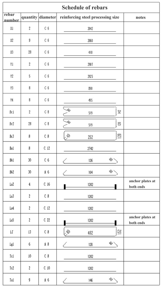
Figure 12.
Schedule of the rebars for the balcony board No. YTB-01-1260.
4.3. Results and Analysis
Using the cantilevered structural components in this prefabricated building project as an example, the modular design tool developed in this paper was validated for its authenticity and applicability. Traditional modeling in Revit and modular tool-based modeling were employed, and a comparison of their modeling effectiveness is presented in Table 3.
Table 3.
Modular design approach compared to the traditional modeling approach.
The result shows that, compared to traditional modeling tools, the cantilever structural component modular design tool based on KBE can improve the efficiency of design personnel by 72.92%. Among them, this tool can complete the modeling design for 6158 prefabricated components in the project, accounting for 96.1%, while it cannot fulfill the modeling design requirements for 238 prefabricated components, accounting for 3.9%. Among them, 238 component design failures occurred due to abnormal component modeling, which was beyond the scope of the module library in the current system and could not be generated automatically, temporarily requiring designers to create them manually. The experimental data indicate that this tool is well-suited for the modeling design process of the vast majority of prefabricated cantilevered components.
The modular design tool automatically retrieves component-related data and conducts structural verification on the generated components. This method improves the structural safety of components through digital platform calculations. During the process of modifying and creating reinforcement, designers can quickly update reinforcement layouts, diameters, or types without the need to regenerate the entire component or module, greatly enhancing the efficiency of design changes.
Factory and construction personnel can use the BOM information to clearly identify the component’s information parameters, including reinforcement data sheets, template mold specifications, and embedded part details. The information is crucial for factory production and on-site construction. The factory can further optimize its operations by aligning the component specifications with its existing inventory, resulting in reduced production lead times, which aids in reducing the production cycle and facilitating a well-organized schedule for component and part allocation.
5. Discussion
At present, both domestic and international scholars [41,42] primarily focus on the parametric modeling of prefabricated components, enabling the digital design of such components. However, most research is geared towards generic component models, with relatively limited investigation into parametric design for complex-shaped prefabricated components. Previous research cannot meet the rapid generation of large quantities of prefabricated components and the design process needs considerable modification, wasting time and manpower, which greatly affects the design efficiency. According to the design complexities of highly intricate prefabricated components, this paper developed a knowledge-based engineering (KBE) modular design tool for cantilevered structural components. The tool aims to fill the existing research gap in the field. This study employed modular design and composite assembly to create target components and made a limited number of modules into an unlimited number of PC components, thereby enhancing design accuracy, which achieves an organic fusion of diverse and standardized design. Consequently, this approach accomplishes knowledge-driven innovation. Furthermore, to enhance the structural soundness and safety of the model designs, an additional function of verification and modification was developed. This function enables the regeneration of individual modules, significantly improving the efficiency of design changes. Additionally, the component management feature developed in this paper enables the reuse of experience during the production and construction phases: automatically generating BOM requests, facilitating customized production at the factory, optimizing on-site component scheduling, and enhancing data connectivity among design, factory, and construction. The design method proposed in this paper is conducive to the development and application of prefabricated construction and BIM technology. For curved components in buildings, the methodology proposed in this paper remains applicable to their design. In the building module library phase, a parametric family of curved components is created using Revit. These family files are then instantiated through secondary development techniques. During the instantiation process, “Arc.Create”, “CurveLoop”, “Create.NewCrossFitting” and other related functions in the API are available for use. Finally, the creation of the target component is completed by module assembly.
However, the research in this paper has some limitations: (1) The research object of this paper is reinforced concrete structural members. There are fewer studies on the more popular concrete–steel structures, and the research related to such components can be continuously promoted in the future. Further research should expand the scope of application of modular design methods. (2) During the modeling process using the modular design tool, there were a few components that could not be modeled. This shows that the model base in the current research system still needs to be expanded. In the future, the modular libraries can be expanded continuously to improve the degree of component diversification and meet the design needs of more complex components. (3) The design concept based on KBE and the methodology of quadratic split modularity in this paper are applicable to all regions. However, due to the specifications of different regions, the design rules of prefabricated components are also different, resulting in the rule engine needing to be adjusted according to the local code requirements. (4) At present, deep learning (DL) [43], artificial intelligence (AI) [44], data mining (DM) [45], and neural networks [46] have a significant impact on various branches of civil engineering. These approaches have been extensively employed in numerical modeling, predicting interest fields and designing engineering structures. Therefore, intelligent modelling or intelligent design is gradually becoming a trend [47,48,49,50]. In future research, especially in the tool development phase, relevant algorithms can be introduced. In this way, not only can a duplicate or redundant code be optimized, but also the number of iterations can be reduced. This measure leads to an increase in the speed of the operation of the system and thus a significant increase in the efficiency of the component design.
6. Conclusions
This paper formalized existing design knowledge and rules using Revit’s secondary development techniques and developed a program for the modular design of prefabricated cantilevered structural components based on knowledge-based engineering (KBE). It included designing functional panels and their corresponding user interfaces to enhance the tool’s usability. The creation of the modular components’ library lays the foundation for the subsequent modular design of prefabricated components. Verifying and assessing the structural functionality of components, making targeted modifications to reinforcement within modules, automatically annotating component numbers, and exporting corresponding rebar material information all contribute to providing valuable references for subsequent production and installation. Based on these steps, the modular design process for cantilevered structural components was achieved, leading to the following conclusions:
- (1)
- Based on the theoretical framework of KBE, this study systematically organized knowledge related to the design parameters and structural requirements of cantilevered structural components, adhering to the principles of secondary split modularization and modulars coordination. The aim was to achieve knowledge reuse and accomplish the meticulous design of components, thereby enhancing the versatility of module utilization. Utilizing rule libraries obtained through KBE knowledge decomposition, components were subjected to verification and assessment, ensuring structural safety and rationality before production. This enhanced component precision and quality, while effectively reducing the design cycle and preventing cost overruns. Additionally, this paper developed a component management function based on design knowledge for manufacturing and assembly. This function automatically stores component information, facilitates model information sharing, and strengthens data connectivity between design, production, and construction processes. It aids in factory mass production while optimizing site scheduling plans to improve construction efficiency that aligns with the industrial batch construction mode.
- (2)
- Utilizing C# language for secondary development of Revit using object-oriented expression methods simplifies complex design knowledge into an intuitive user interface and logical programming language that is easy for users to operate. Through Revit secondary development, module connection issues during the modeling process are effectively resolved by eliminating redundant modeling tasks. Consequently, component modeling efficiency is significantly improved while reducing designers’ workload. The developed tool system exhibits high maintainability as well as allowing future updates to enhance diversified component designs of prefabricated buildings.
Author Contributions
Conceptualization, N.L.; methodology, J.L.; software, X.Y. and Y.F.; formal analysis, J.L.; investigation, X.X.; data curation, Y.F.; writing—original draft preparation, Y.F.; writing review and editing, Y.F.; visualization, X.X. and X.Y.; supervision, N.L. All authors have read and agreed to the published version of the manuscript.
Funding
This research was supported by the Ministry of Housing and Urban-Rural Development of the People’s Republic of China Fund grant (2020-R-094).
Data Availability Statement
Some or all data, models, or code that support the findings of this study are available from the corresponding author upon reasonable request. The data are not publicly available due to being used for subsequent research.
Acknowledgments
We would like to thank Hubei University of Technology and Li’s team for providing technical guidance for this research. Secondly, we would like to thank the leadership of Science and Technology Development Branch, China Construction Third Group Co. for their support. Finally, we gratefully appreciate the technical support from Beijing Olive Hill Software Co., Ltd.
Conflicts of Interest
Author Jixiong Liu was employed by the company Science and Technology Development Branch, China Construction Third Group Co., Ltd. Authors Xiongjin Ye and Xingxing Xie were employed by the company Beijing Olive Hill Software Co., Ltd. This paper is a collaborative project between school and business. The remaining authors declare that the research was conducted in the absence of any commercial or financial relationships that could be construed as a potential conflict of interest.
References
- Jiang, L.; Li, Z.; Li, L.; Gao, Y. Constraints on the promotion of prefabricated construction in China. Sustainability 2018, 10, 2516. [Google Scholar] [CrossRef]
- Qi, Y.; Chang, S.; Ji, Y.; Qi, K. BIM-based incremental cost analysis method of prefabricated buildings in China. Sustainability 2018, 10, 4293. [Google Scholar] [CrossRef]
- Jaillon, L.C. The Evolution of the Use of Prefabrication Techniques in Hong Kong Construction Industry. Ph.D. Thesis, Hong Kong Polytechnic University, Hong Kong, China, 2009. [Google Scholar]
- Li, H.; Guo, H.L.; Skitmore, M.; Huang, T.; Chan, K.Y.N.; Chan, G. Rethinking pre-fabricated construction management using the VP-based IKEA model in Hong Kong. Constr. Manag. Econ. 2011, 29, 233–245. [Google Scholar] [CrossRef]
- Chiu, S.T.L. An Analysis on: The Potential of Prefabricated Construction Industry. Ph.D. Thesis, The University of British Columbia, Vancouver, BC, Canada, 2012. [Google Scholar]
- Wang, J.; Zhao, J.; Hu, Z. Review and thinking on development of building industrialization in China. China Civ. Eng. J. 2016, 49, 1–8. [Google Scholar]
- Ma, G.; Jiang, J.; Shang, S. Visualization of component status information of prefabricated concrete building based on building information modeling and radio frequency identification: A case study in China. Adv. Civ. Eng. 2019, 2019, 6870507. [Google Scholar] [CrossRef]
- Chen, W.; Sun, X.J.; Wang, Z.H.; Chen, R.L.; Li, H. SD model of quality chain management and control of prefabricated building components. J. Civ. Eng. Manag. 2020, 37, 14–20. [Google Scholar]
- Tam, A. Advancing the cause of precast construction in Kwai Chung. Hong Kong Eng. 2007, 35, 9. [Google Scholar]
- Hobson, D.E. A Methodology for the Residential Building Mix Selection in Modular Community Design; Purdue University: West Lafayette, IN, USA, 1975. [Google Scholar]
- Joo, S.J. Scheduling preventive maintenance for modular designed components: A dynamic approach. Eur. J. Oper. Res. 2009, 192, 512–520. [Google Scholar] [CrossRef]
- Liang, N.; Yu, M. Research on design optimization of prefabricated residential houses based on BIM technology. Sci. Program. 2021, 10, 1422680. [Google Scholar] [CrossRef]
- Tam, V.W.; Tam, C.M.; Zeng, S.X.; Ng, W.C. Towards adoption of prefabrication in construction. Build. Environ. 2007, 42, 3642–3654. [Google Scholar] [CrossRef]
- Kang, J.; Dong, W.; Huang, Y. A Bim-Based Automatic Design Optimization Method for Modular Steel Structures: Rectangular Modules as an Example. Buildings 2023, 13, 1410. [Google Scholar] [CrossRef]
- Su, M.; Yang, B.; Wang, X. Research on integrated design of modular steel structure container buildings based on BIM. Adv. Civ. Eng. 2022, 2022, 4574676. [Google Scholar] [CrossRef]
- Ma, R.; Xia, J.; Chang, H.; Xu, B. A component-based model for novel modular connections with inbuild component. Appl. Sci. 2021, 11, 10503. [Google Scholar] [CrossRef]
- Lin, M.S.; Lu, H.Y.; Liu, J.Y. Study on parametric design of assembled structure shear wall based on virtual reality technology. Build. Struct. 2018, 48, 644–647. [Google Scholar]
- Nikkhoo, A.; Banihashemi, S.; Kiani, K. On non-stationary response of cracked thin rectangular plates acted upon by a moving random force. Sci. Iran. 2023, in press. [Google Scholar] [CrossRef]
- Nikkhoo, A.; Banihashemi, S.; Kiani, K. Parametric investigations into dynamics of cracked thin rectangular plates excited by a moving mass. Sci. Iran. 2023, 30, 860–876. [Google Scholar] [CrossRef]
- Amiri, J.V.; Nikkhoo, A.; Davoodi, M.R.; Hassanabadi, M.E. Vibration analysis of a Mindlin elastic plate under a moving mass excitation by eigenfunction expansion method. Thin-Walled Struct. 2013, 62, 53–64. [Google Scholar] [CrossRef]
- Rofooei, F.R.; Nikkhoo, A. Application of active piezoelectric patches in controlling the dynamic response of a thin rectangular plate under a moving mass. Int. J. Solids Struct. 2009, 46, 2429–2443. [Google Scholar] [CrossRef]
- Kiani, K. Vibrations of biaxially tensioned-embedded nanoplates for nanoparticle delivery. Indian J. Sci. Technol. 2013, 6, 4894–4902. [Google Scholar] [CrossRef]
- Tan, T.; Mills, G.; Papadonikolaki, E.; Li, B.; Huang, J. Digital-enabled Design for Manufacture and Assembly (DfMA) in offsite construction: A modularity perspective for the product and process integration. Archit. Eng. Des. Manag. 2023, 19, 267–282. [Google Scholar] [CrossRef]
- Abrishami, S.; Martín-Durán, R. BIM and DfMA: A paradigm of new opportunities. Sustainability 2021, 13, 9591. [Google Scholar] [CrossRef]
- Li, M.K.; Wong, B.C.; Liu, Y.; Chan, C.M.; Gan, V.J.; Cheng, J.C. DfMA-oriented design optimization for steel reinforcement using BIM and hybrid metaheuristic algorithms. J. Build. Eng. 2021, 44, 103310. [Google Scholar] [CrossRef]
- Iyer, N.; Jayanti, S.; Lou, K.; Kalyanaraman, Y.; Ramani, K. Shape-based searching for product lifecycle applications. Comput.-Aided Des. 2005, 37, 1435–1446. [Google Scholar] [CrossRef][Green Version]
- Ammar, A.A.; Scaravetti, D.; Nadeau, P. Knowledge reuse: Towards a design tool. In Proceedings of the DS 60: Proceedings of DESIGN 2010, the 11th International Design Conference, Dubrovnik, Croatia, 17–20 May 2010; pp. 1451–1460. [Google Scholar]
- Feigenbaum, E.A. Knowledge Engineering: The Applied Side of Artificial Intelligence. Ann. N. Y. Acad. Sci. 1984, 426, 91–107. [Google Scholar] [CrossRef] [PubMed]
- Verhagen, W.J.; Bermell-Garcia, P.; Van Dijk, R.E.; Curran, R. A critical review of Knowledge-Based Engineering: An identification of research challenges. Adv. Eng. Inform. 2012, 26, 5–15. [Google Scholar] [CrossRef]
- La Rocca, G. Knowledge based engineering: Between AI and CAD. Review of a language based technology to support engineering design. Adv. Eng. Inform. 2012, 26, 159–179. [Google Scholar] [CrossRef]
- Yurin, A.Y.; Dorodnykh, N.O.; Shigarov, A.O. Semi-automated formalization and representation of the engineering knowledge extracted from spreadsheet data. IEEE Access 2021, 9, 157468–157481. [Google Scholar] [CrossRef]
- Baxter, D.; Gao, J.; Case, K.; Harding, J.; Young, B.; Cochrane, S.; Dani, S. An engineering design knowledge reuse methodology using process modelling. Res. Eng. Des. 2007, 18, 37–48. [Google Scholar] [CrossRef]
- Bryson, J.; Cox, J.J.; Carson, T.J. A product development scenario for knowledge capture and reuse. Comput.-Aided Des. Appl. 2009, 6, 207–218. [Google Scholar] [CrossRef]
- Corallo, A.; Laubacher, R.; Margherita, A.; Turrisi, G. Enhancing product development through knowledge-based engineering. J. Manuf. Technol. Manag. 2009, 20, 1070–1083. [Google Scholar] [CrossRef]
- Li, Z.; Jin, X.; Jia, H.Y. The knowledge representation and reuse in product design. J. Shanghai Jiaotong Univ. 2006, 40, 1183–1186. [Google Scholar]
- Gembarski, P.C.; Li, H.; Lachmayer, R. KBE-modeling techniques in standard CAD-systems: Case study—Autodesk inventor professional. In Managing Complexity, Proceedings of the 8th World Conference on Mass Customization, Montreal, QC, Canada, 20–22 October 2015; Springer International Publishing: Berlin/Heidelberg, Germany, 2017; pp. 215–233. [Google Scholar]
- Chen, Y.L.; Xu, Y.S.; Qi, E.M. Research and development of rapid design platform for mechanical products. J. Tianjin Univ. 2002, 6, 744–748. [Google Scholar]
- Kügler, P.; Dworschak, F.; Schleich, B.; Wartzack, S. The evolution of knowledge-based engineering from a design research perspective: Literature review 2012–2021. Adv. Eng. Inform. 2023, 55, 101892. [Google Scholar] [CrossRef]
- Chapman, C.B.; Pinfold, M. The application of a knowledge based engineering approach to the rapid design and analysis of an automotive structure. Adv. Eng. Softw. 2001, 32, 903–912. [Google Scholar] [CrossRef]
- Li, J.; Lu, S.; Wang, W.; Huang, J.; Chen, X.; Wang, J. Design and climate-responsiveness performance evaluation of an integrated envelope for modular prefabricated buildings. Adv. Mater. Sci. Eng. 2018, 2018, 8082368. [Google Scholar] [CrossRef]
- Wang, D.; Hu, Y. Research on the Intelligent Construction of the Rebar Project Based on BIM. Appl. Sci. 2022, 12, 5596. [Google Scholar] [CrossRef]
- Shi, Y.P.; Sun, F.; Li, F.; Wang, D.; Zhu, J. Research on secondary development of prefabricated walls based on BIM. China Concr. Cem. Prod. 2021, 6, 80–84. [Google Scholar]
- Rodrigues, F.; Cotella, V.; Rodrigues, H.; Rocha, E.; Freitas, F.; Matos, R. Application of deep learning approach for the classification of buildings’ degradation state in a BIM methodology. Appl. Sci. 2022, 12, 7403. [Google Scholar] [CrossRef]
- Jia, Z.; Wang, W.; Zhang, J.; Li, H. Contact High-Temperature Strain Automatic Calibration and Precision Compensation Research. J. Artif. Intell. Technol. 2022, 2, 69–76. [Google Scholar]
- Hu, X.; Kuang, Q.; Cai, Q.; Xue, Y.; Zhou, W.; Li, Y. A Coherent Pattern Mining Algorithm Based on All Contiguous Column Bicluster. J. Artif. Intell. Technol. 2022, 2, 80–92. [Google Scholar] [CrossRef]
- Du, H.; Du, S.; Li, W. Probabilistic time series forecasting with deep non-linear state space models. CAAI Trans. Intell. Technol. 2023, 8, 3–13. [Google Scholar] [CrossRef]
- Chen, J.; Yu, S.; Wei, W.; Ma, Y. Matrix-based method for solving decision domains of neighbourhood multigranulation decision-theoretic rough sets. CAAI Trans. Intell. Technol. 2022, 7, 313–327. [Google Scholar] [CrossRef]
- Liu, C.; ME Sepasgozar, S.; Shirowzhan, S.; Mohammadi, G. Applications of object detection in modular construction based on a comparative evaluation of deep learning algorithms. Constr. Innov. 2022, 22, 141–159. [Google Scholar] [CrossRef]
- Zhang, Z.; De Luca, G.; Archambault, B.; Chavez, J.; Rice, B. Traffic Dataset and Dynamic Routing Algorithm in Traffic Simulation. J. Artif. Intell. Technol. 2022, 3, 111–122. [Google Scholar] [CrossRef]
- Zhao, H.; Ma, L. Several rough set models in quotient space. CAAI Trans. Intell. Technol. 2022, 7, 69–80. [Google Scholar] [CrossRef]


Disclaimer/Publisher’s Note: The statements, opinions and data contained in all publications are solely those of the individual author(s) and contributor(s) and not of MDPI and/or the editor(s). MDPI and/or the editor(s) disclaim responsibility for any injury to people or property resulting from any ideas, methods, instructions or products referred to in the content. |
© 2023 by the authors. Licensee MDPI, Basel, Switzerland. This article is an open access article distributed under the terms and conditions of the Creative Commons Attribution (CC BY) license (https://creativecommons.org/licenses/by/4.0/).