Abstract
This paper investigates the seismic performance of two adjacent buildings connected by viscous dampers. Three types of damper placement are discussed, including installing dampers within a single building, connecting two buildings at the same floor level, and connecting two buildings at the inter-story level. Analytical models are established to consider various dynamic properties of the adjacent buildings, and the theoretical solutions are obtained, including the transmissibility curves, additional modal damping, and input energy under the seismic design spectrum. Time history analyses of an engineering project are performed with different damper placements. Different numerical models are compared for frequently and rarely occurred earthquakes. The seismic mitigation effect is discussed with regard to the story drift reduction rate and dynamic energy. Theoretical and numerical results demonstrate that the connecting dampers provide added modal damping while causing the coupled response. As a result, it is less efficient than traditional ways of placement within a building. Furthermore, the connecting dampers significantly increase the reaction of the floors without installed dampers. When designing dampers to connect the adjacent buildings, careful engineering calculations should be made.
1. Introduction
Metropolitan buildings are constructed more closely with the growing population and limited land resources. Many commercial buildings are composed of a low-rise podium along with tall towers. For some, podiums and towers are built as a whole structure, but for many others, they are built independently with construction joints. Joints also separate buildings with large or irregular plan sizes. Considering these reasons, researchers and engineers proposed connecting the separated structures using energy dissipative devices to lower seismic damage, the possibility of pounding, or wind-induced vibration [1].
Traditional passive dampers are studied as connectors, which are viscous dampers in the early stage. Luco et al. [2] studied the dynamic response of two adjacent buildings with different heights connected by viscous dampers. The optimal damping values are discussed regarding the different properties of the two buildings. The controlling strategies have been verified by Xu et al. [3] and Zhang et al. [4] using analytical and numerical approaches. Tubaldi et al. [5] presented a performance-based methodology for the seismic assessment of two steel-type buildings connected by viscous dampers and found out that the seismic performance is sensitive to the viscous properties of the dampers. Yang and Lam [6] studied the dynamic response of two buildings connected by viscoelastic dampers under bidirectional excitations. It is concluded that the bidirectional input can increase the reactions of coupled asymmetric buildings, and the installation dampers may induce a sudden change in the lateral stiffness of the taller building.
For experiment verifications, several small-scaled shaking table tests were performed to validate the controlling effect by Xu et al. [7]. Yang et al. [8] performed comparative experiments to verify the seismic mitigation effect using viscous dampers to connect a scaled five-story and a six-story steel frame. A significant increment in modal damping is observed while the natural frequencies remain almost unchanged. Wu et al. [9] conducted shaking table tests for two adjacent isolated steel frames connected by viscous dampers. Test results proved that the dampers could help reduce the overturning effect and maximum bearing deformation for adjacent high-rise isolated structures. In addition to viscous dampers, other passive energy dissipative devices are studied, including viscoelastic dampers [10], friction dampers [11], tuned mass dampers [12], inertial mass dampers [13], negative stiffness devices [14], etc.
Researchers focus on the optimal placement of dampers for passive devices to connect adjacent buildings. Bigdeli et al. [15] simplify the optimization process as a bi-level optimization problem and compares five methods to solve the problem. Theoretical and numerical studies are also performed to verify the optimizing results [16,17]. Tubaldi et al. [18] used the linearized reduced-order model of the coupled system to establish a simplified design method for both linear and nonlinear dampers between adjacent buildings. The simplified design method is verified by time history analysis. Palermo and Silvestri [19] studied the optimal additional damping for connecting viscous dampers and the trends of damping reduction factors concerning the main dynamic parameters of the coupled systems.
Other strategies to connect the adjacent buildings adopt active or semi-active technologies. Ou and Li [20] investigated the characteristics of forces in active control systems connected to adjacent buildings. The design approach for all control devices is proposed based on the results, which can provide an expected reduction in seismic response. Xu et al. [13] proposed using active tuned mass dampers on the adjacent buildings’ top floors combined with viscous dampers and numerically verified the vibration controlling effect. Uz and Hadi [21] studied the adoption of Magnetorheological (MR) dampers and the corresponding optimal design process. It has been proved that the controlling technology can enhance seismic performance economically. Guenidi et al. [22] numerically investigated using shared tuned mass damper (TMD) and MR dampers and concluded that a shared TMD could provide adequate response reduction compared to that obtained using two TMDs separately. Al-Fahdawi et al. [23,24] compared the controlling benefits by connecting two adjacent buildings using passive viscous and MR dampers with properly designed control algorithms. The reduction in story drift and absolute acceleration are compared, and it is concluded that the active control method (MR dampers) is more effective than the traditional passive device.
The above literature focuses on connecting the two adjacent buildings to reduce seismic damage. In addition, the pounding prevention and wind-induced vibration controlling effect are discussed and verified by refs. [25,26,27,28,29,30,31], in which many energy dissipative devices are also included. Nevertheless, most of the present studies did not consider the soil–structure interaction. Further research is required to include the SSI effect on the seismic response of connected adjacent buildings, but not for lightweight structures [32,33,34].
Although many studies have explored reducing seismic action between two adjacent buildings using energy dissipation devices, most of them discussed the most likely benefit of the dampers. The complex situations are not thoroughly studied, including the adjacent buildings’ different dynamic properties and nonlinear seismic behavior. The main contribution of this paper is the detailed analytical and numerical investigations to study the seismic performance of connecting adjacent buildings with dampers. The possible adverse effect caused by the additional dampers is discussed. In addition, a new connecting type is proposed by installing dampers between the inter-story levels, and the controlling efficiency is compared. Discrete simplified analytical models are established, and the transmissibility law is compared considering the different properties of the adjacent buildings. Nonlinear time history (NLTH) analyses are also performed to validate the theoretical results based on an actual engineering project.
2. Problem Statement
2.1. Analytical Model
Adjacent buildings are idealized as linear shear-type models. The mass is concentrated at the centers of the floors. For the comparison of damper placement, three analytical models are established as multi-degree of freedom (MDOF) systems, as shown in Figure 1:
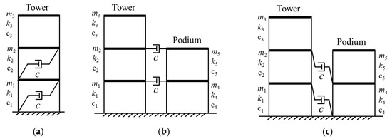
Figure 1.
MODF analytical model with different damper layouts: (a) Model a: with single building placement; (b) Model b: with same level placement; (c) Model c: with inter-story placement.
- (1)
- Model a: The tower with dampers installed within the building;
- (2)
- Model b: Two adjacent buildings connected by dampers at the same story level;
- (3)
- Model c: Two adjacent buildings with inter-story damper placement.
2.2. Equations of Motion
For the different analytical models in Section 2.1, the equation of motion can be described as,
where M, C, and K are the mass, damping, and stiffness matrices, respectively. c is the additional damping coefficient provided by a single viscous damper element. , , and are the relative acceleration, velocity, and displacement matrices of the system, respectively. I is the unit vector with all elements equal to 1, and is the time history of the ground motion.
The mass, damping, and stiffness matrices of Model a–Model c are given as follows,
where , , and are the mass matrices, , , and are the damping matrices with added viscous dampers, and , , and are the stiffness matrices of Model a–Model c, respectively. c1–c5, and k1–k5 represent the story stiffness value and the damping coefficient for the 1st–5th story, respectively.
2.3. Transmissibility in Frequency Domain
For the motion of equations given in Equation (1), it can be transformed into the frequency domain using Fourier transformation for both sides of the equation as
where , .
The displacement transmissibility between the i-th floor and the base can be obtained,
where denotes the displacement transmissibility between the ground and the i-th degree of freedom.
The acceleration transmissibility of the i-th floor is
3. Analytical Results
3.1. Model Parameters
The 5-DOF analytical models were established to simulate the main tower building constructed with a bottom podium. Different engineering situations where the adjacent tower and podium usually have different or similar architectural heights and dynamic properties were included. Different dynamic properties of the adjacent buildings could lead to different seismic performances of the connecting dampers. Cases No. 1, No. 2, and No. 3 were used to reflect the differences between the two adjacent structures by changing the mass and stiffness of the degree of freedom. The story mass and stiffness are listed in Table 1, and inherent structural damping matrices are simplified using Rayleigh damping matrices by assuming the first two-order modal damping ratio to be 5%. The natural periods of the 5-DOF model in different cases are given in Table 2, and the normalized mode shapes are presented in Figure 2. The first natural period of the tower for different cases varies from 2.11 to 3.17 s, with slight differences in the second and third periods and the normalized modal shapes.

Table 1.
Structural parameters of the 5-DOF models.
Table 2.
Natural periods of the 5-DOF models with different parameter cases (without dampers).
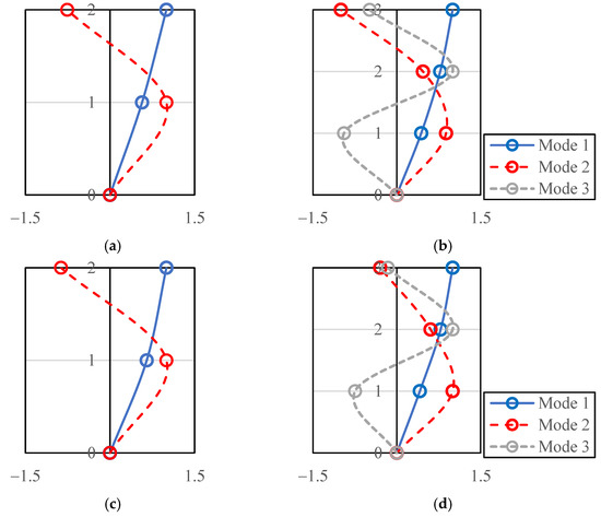
Figure 2.
The normalized mode shapes: (a) Podium of Case No. 1 and No. 3; (b) Tower of Case No.1 and No. 2; (c) Podium of case No. 2; (d) Tower of Case No. 3.
For simplicity, it is assumed that the viscous linear dampers can provide a 6% additional damping ratio for the podium. The corresponding damping coefficients are calculated from the modal damping matrices of the podium as c = 216 kN·s2/m.
3.2. Transimissibility Comparison
Based on the transmission equations in Equations (10) and (11), the top floor acceleration transmissibility is presented in Figure 3a. It has been proved that the damper can reduce dynamic response by providing additional modal damping for all modes. However, due to the installation of connecting dampers, the dynamic response is coupled, and the coupled response can be significantly observed in the frequency domain. The podium is influenced more obviously than the tower because of the difference in structural size. Due to the contribution of the coupled response, the dynamic motion may be amplified under earthquakes.
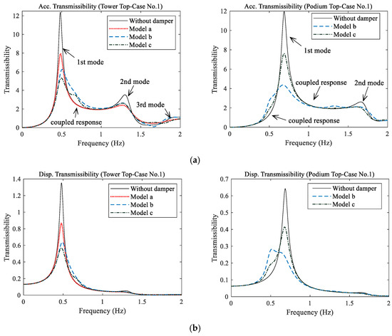
Figure 3.
Transmissibility of the tower and podium (Case No. 1): (a) absolute top acceleration; (b) absolute top displacement.
The main factors induced by the connecting dampers that can affect the seismic response of the tower and the podium are: (1) additional modal damping by the energy dissipation of dampers; and (2) the coupled dynamic response, which is essentially caused by the phase difference between the two ends of the damper under motion. Additional modal damping is always beneficial for reducing the seismic response; however, the amplification phenomena due to the coupling increase the complexity of the connecting system. Figure 3b presents the top displacement transmissibility for the tower and podium. Compared with the acceleration response, the displacement response mainly depends on the first mode contribution, and the higher mode response is minor. At the same time, the coupled response is also significant for the podium structure.
3.3. Quantification of Additional Modal Damping
The Levy Method [35] is a widely accepted system identification algorithm that adopts a mathematic transmission model to fit the frequency data in a least-squares sense. This method can calculate the modal damping from the absolute acceleration transfer function. The modal damping ratios of the all modes are obtained and compared herein. The additional modal damping ratio is obtained by the identified damping ratio minus the original modal damping. The results are discussed considering different structural parameters in Figure 4. The main conclusions are:
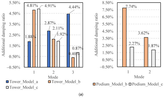
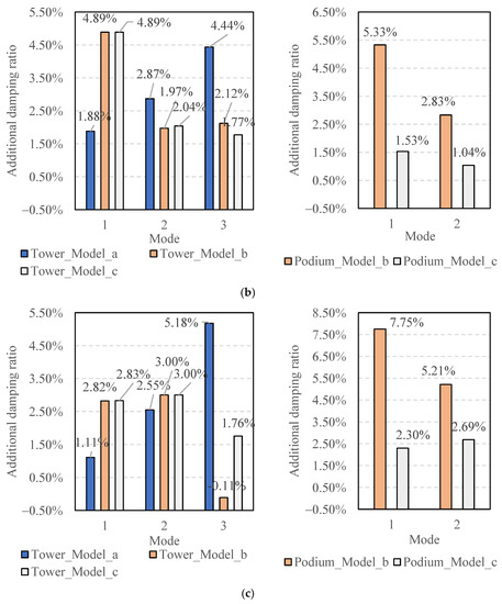
Figure 4.
Additional damping ratio under different damper placement with 6% damping level: (a) Case No. 1; (b) Case No. 2; (c) Case No. 3.
- (a)
- The damper layout in Model a (installed within the tower building) provides more significant modal damping in higher modes, while the dampers in Model b and Model c that connect buildings can dissipate more energy in the first mode response;
- (b)
- Dampers in Model b and Model c have similar performance for providing additional modal damping;
- (c)
- Under specific circumstances, dampers can decrease the modal damping ratio (minus the modal damping ratio). That is because if the coupled response is near the modal frequency, the transmissibility value will increase, and the identified modal damping using the Levey Method will decrease accordingly.
Figure 4a,b present the additional damping ratio for Case No. 1 and No. 2. For these two cases, the bottom podium of Case No.2 is more rigid. The natural period of the podium in Case No. 1 and No. 2 is 1.45 s and 0.97 s, respectively. Results illustrate that the modal damping in higher modes of tower building increase owing to the rigid podium. For the podium, the modal damping significantly increases in Model b but decreases in Model c.
Figure 4a,c show the additional damping ratio for Case No. 1 and No. 3. For these two cases, the bottom podium of Case No.3 is softer to represent a high-rise tower building. The natural period of the tower in Case No. 1 and No. 3 is 2.08 s and 3.17 s respectively. The damping ratio for the tower decreases in Case No. 3 because the tower size becomes significantly larger. The third mode additional damping ratio is a minus value, which amplifies the third mode response. The podium damping ratio obtains an increment in modal damping, primarily for Model b.
3.4. Seismic Input Energy
Though the additional modal damping ratio has been compared in Section 3.3, evaluating the damping benefits with different damper layouts for the whole structural system is challenging. Even though a higher first mode damping ratio is obtained using connecting dampers, a significant coupled response is observed (Figure 3), which can amplify the dynamic response.
The seismic input energy is calculated and compared to appropriately evaluate the seismic mitigation effect. The ordinary approach to obtaining input energy is to conduct a time history analysis, though the energy can be calculated more briefly in the frequency domain,
where is the Fourier Transform of the seismic wave in the time range between 0 and t. is the energy transfer function given in the following form,
The design spectrum of the Chinese Code [36] is adopted and transformed into the power spectrum as
where is the power spectrum of the seismic input. is the design acceleration spectrum with designated damping ratio ξ. T is the duration of the earthquake and P is the exceedance probability (T = 30 s, P = 0.85 in this paper). It is assumed that the phase angle of the seismic wave is random. Thus, the code-based artificial wave can be formed by the trigonometric series. The selected design spectrum and generated artificial spectrum after iterative correction are given in Figure 5 and Figure 6. The characteristic period of the selected spectrum is 0.40 s, and the damping ratio is 5%. The peak acceleration value is 70 cm/s2, corresponding to the frequent earthquakes of fortification intensity of eight in the Chinese Code [36].
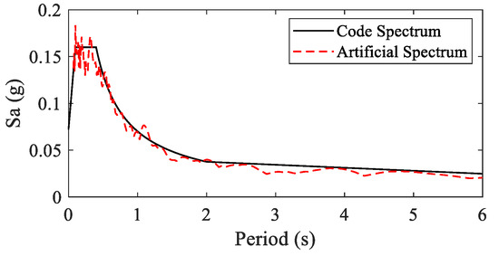
Figure 5.
Seismic design spectrum and artificial spectrum.
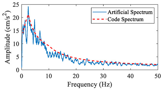
Figure 6.
Fourier spectrum generated by the Code and the artificial spectrum.
Energy comparison in time history is calculated by Equation (12). The energy is calculated using the frequency domain method, while the step-by-step approach is used in the time domain to obtain incremental results. An example is given in Figure 7. It presents the seismic input energy for Case No. 1 of each degree of freedom in Figure 1. The input energy can accurately capture the seismic response of each floor, especially including both the effect of energy dissipation of dampers and the coupled response. It is concluded that installing dampers on the lower floors of the tower will increase the seismic response on the upper floors (3-DOF). The connecting dampers in Model b are likely to increase the seismic response of the tower but with a significant seismic reduction effect for the podium.
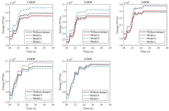
Figure 7.
Seismic input energy for each degree of freedom (DOF) of tower and podium (Case No. 1).
In comparison, Model b can reduce the dynamic response of the tower but amplify the podium response. According to Figure 4a, the additional modal damping of Model b and Model c are similar for the tower but are higher for the podium of Model b, leading to a significant seismic reduction effect. The energy results for the tower can be explained in Figure 3: For Model b, the coupled response is remarkable in the frequency domain between 0.5 and 1.0 Hz, which is caused by the first mode response of the podium. Figure 6 also presents that the seismic energy is high in the same frequency range as the Fourier spectrum generated by the Code.
The seismic input energy reduction ratio is defined to evaluate the damping effect provided by different layouts of dampers,
where EI is the seismic input energy (total dissipated energy at the final time step) of the structures without dampers. EId is the seismic input energy of the damped structure.
The energy reduction ratio is summarized in Figure 8, Figure 9 and Figure 10, including different adjacent building cases and damper layout models. The main conclusions that can be made from the comparison results are: (a) All the damper layouts will increase the response on the upper floor of towers, especially for the dampers connecting two adjacent buildings. (b) For the traditional damper layout in the single tower in Model a, the energy dissipation effect is guaranteed for the tower. While the dynamic response will increase in many cases considered in this study due to the coupled response of the adjacent buildings. (c) The damping effect caused by the connecting dampers is significantly influenced by the dynamic properties of the two adjacent buildings. From Case No. 1 to Case No. 2, the damper is more beneficial for the tower, with the podium becoming rigid. In addition, comparing Case No. 1 and Case No. 3, the dampers are more effective for both the tower and podium with a higher tower building. The response energy results conclude that the dampers connecting two buildings are not always beneficial for the seismic response. If dampers are designed to connect two adjacent buildings, a detailed analysis should be made to fully consider the possible adverse effect.
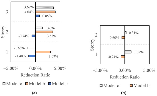
Figure 8.
Energy reduction ratio of Case No. 1: (a) Tower; (b) Podium.
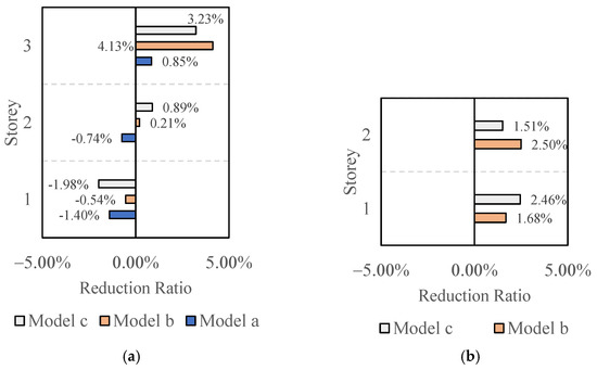
Figure 9.
Energy reduction ratio of Case No. 2: (a) Tower; (b) Podium.
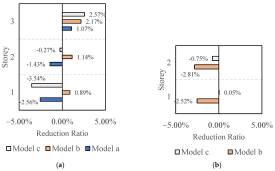
Figure 10.
Energy reduction ratio of Case No. 3: (a) Tower; (b) Podium.
4. Engineering Verification
The different damper layouts in adjacent building models have been discussed thoroughly in analytical solutions regarding energy in Section 3. In general, results show that the dampers that connect two adjacent buildings may increase the dynamic response in some circumstances instead of dissipating the motion energy. Numerical studies examine the seismic response of the two adjacent buildings with dampers.
4.1. Numerical Model
Figure 11 presents a 23-story reinforced concrete (RC) frame shear wall building with an adjacent 10-story steel moment frame as the podium. In between is a construction joint, which divides the two buildings. The numerical model is based on an actual project in Yunnan Province, China, designed by the China Southwest Architectural Design and Research Institute. The basic dynamic properties are listed in Table 3. Due to the architectural function, the maximum number of dampers in the global x-direction is limited. Linear viscous dampers are installed within the tower and across the construction joint in the x-direction to satisfy the seismic mitigation requirement of the RC tower. After the preliminary design, the viscous damping coefficient of viscous dampers is taken as 36,300 kN·s/m, providing a 50-ton maximum damping force.
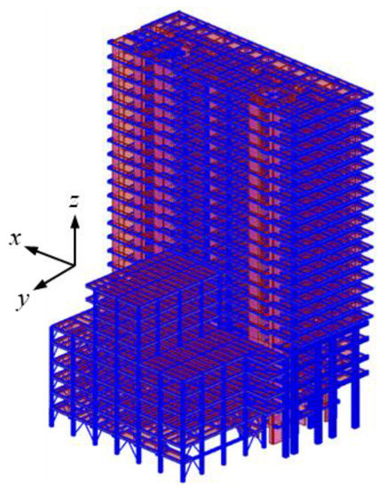
Figure 11.
The numerical model of adjacent buildings.
Table 3.
Dynamic properties of adjacent tower and podium.
The SAP2000 v22.0 software was adopted to implement the seismic performance simulation of the case study. For the nonlinear behavior of columns and beams, the P-M2-M3 and M3 hinges were defined, respectively. The steel moment frame podium braces were modelled using the P hinges. The shear walls were defined using the nonlinear layered shells, in which the concrete and rebar were defined separately using layers with designated thickness and positions. The section size and rebars defined in the model are based on the actual engineering design. For the viscous dampers, the link element represents the Maxwell model.
Based on the Chinese Design Code [36], two field-recorded seismic waves and one code-based artificial wave (AW) were selected to evaluate the building performance. The process of generating the AW wave is described in Section 3.4. The detailed information is given in Table 4, the response spectrum is compared with the code spectrum in Figure 12, and the normalized acceleration time history excitation is given in Figure 13. To include the damper performance under different seismic magnitudes, seismic performance analysis with a peak acceleration of 70 gal and 400 gal represents frequently and rarely occurred earthquakes.
Table 4.
The information of seismic waves.
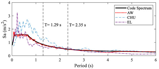
Figure 12.
Spectrum comparison between the seismic waves and the Code spectrum.
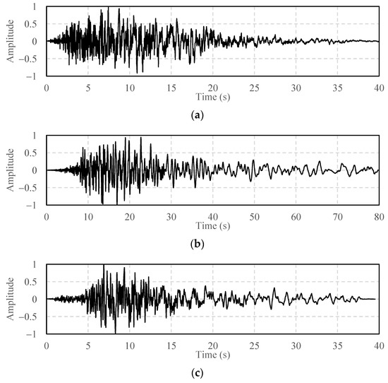
Figure 13.
Normalized acceleration time history of the seismic records: (a) AW; (b) CHE; (c) EL.
4.2. Models with Different Damper Layout
Models with different damper layouts are established to compare the seismic controlling effect via time history analysis:
- (1)
- Original model: RC tower without viscous dampers;
- (2)
- Model A: Few viscous dampers installed within the tower;
- (3)
- Model B: Additional dampers installed on the same level across the construction joint (based on Model A);
- (4)
- Model C: Additional dampers in the inter-story layout (based on Model A).
Figure 14 presents an illustrative sketch of the dampers designed within the tower in a typical story. Dampers in the x-direction are installed at positions ① and ②, while positions ③–⑤ for dampers in the y-direction. In positions ① and ③, dampers are placed from the second floor to the top floor (the 23rd floor) and from the fourth floor to the top floor for other positions. In total, 42 and 62 dampers are used separately in the x and y-direction.
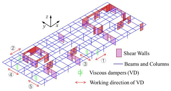
Figure 14.
Typical placement of dampers within the towers.
The dampers that connect the two buildings are installed differently in Model B and Model C. The additional dampers are all considered to be used in the x-direction to investigate whether they can provide an approximately identical supplemental damping as in the y-direction. The placement of dampers is presented in Figure 15.
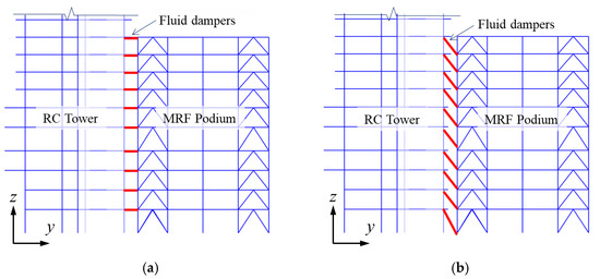
Figure 15.
Connecting damper placement for the two adjacent buildings: (a) Model B; (b) Model C.
4.3. Seismic Response under Frequent Earthquakes
The dynamic seismic response of different models in the x-direction is calculated via time history analysis, and the maximum story drift is obtained. The Maxwell model is adopted to model the viscous dampers, and the Fast Nonlinear Analysis (FNA) method is used to calculate the time history response of the elastic model with limited nonlinear components (viscous damper elements). The drift reduction rate is calculated accordingly to compare the damping effect. Figure 16 presents the drift reduction results from the original model to Model A. It is concluded that the viscous dampers can significantly reduce the maximum story drift under frequent earthquakes at an average rate of about 20%.
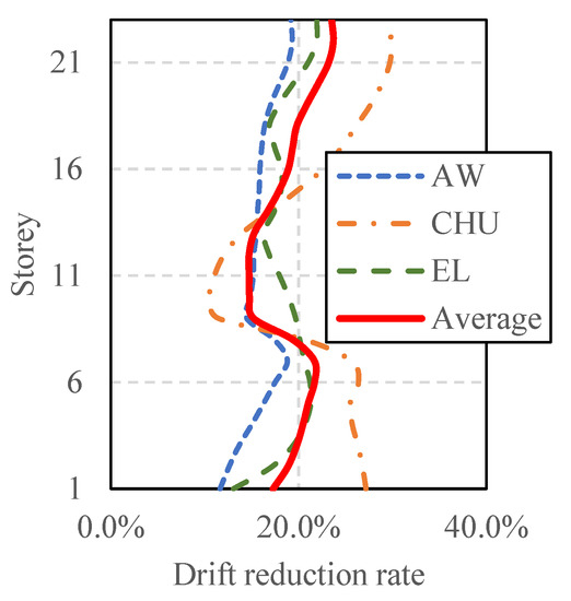
Figure 16.
Drift reduction rate between original RC tower and Model A.
The drift reduction rate between Model A and Model B is presented in Figure 17. According to the drift comparison, the seismic response is amplified on the upper floors after installing the dampers to connect the two adjacent buildings. In contrast, the seismic mitigation effect is observed on the bottom floors with connecting dampers. Based on the average value of the three seismic waves, the amplification and reduction rates are between 0 and 5%. The results correspond to the analytical seismic energy comparison in Figure 8, Figure 9 and Figure 10.
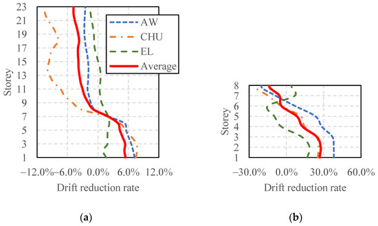
Figure 17.
Drift reduction rate between Model A and Model B: (a) RC tower; (b) Steel podium.
The drift reduction rate between Model B and Model C is presented in Figure 18. The damper placement is different (see Figure 15). According to the seismic reduction rate, it is concluded that the dampers in Model C can provide a better controlling effect for both the RC tower and the steel podium based on average meaning. However, the dampers still cause adverse effects on the upper floors of the RC tower.
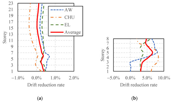
Figure 18.
Drift reduction rate between Model B and Model C: (a) RC tower; (b) Steel podium.
4.4. Nonlinear Response under Rare Earthquake
Although multiple theoretical and numerical analyses have been compared to study the behavior of the dampers connecting adjacent buildings in this paper and previous studies, most of which utilized the elastic model. The nonlinear response of connected buildings under rarely occurred earthquakes should be investigated in detail. The time history response is calculated using the step-by-step method. The details of structural members, including the rebars, are included based on actual engineering designs to reflect the nonlinear response more accurately. Due to the computing time, only the result of the AW wave is calculated in this section.
The story drift reduction rate of Models A, B, and C compared to the original model are given in Figure 19. The drift of Model A is slightly amplified on floors 1–5 because there are no dampers on the first floor and fewer dampers on the second and third floors. It is concluded that the maximum story drift of upper floors can be reduced between 0% and 10% with additional viscous dampers. The drift reduction rate under rare earthquakes significantly differs from that of frequent earthquakes (Figure 16). The overall seismic mitigation efficiency is lower than cases under frequent earthquakes due to the nonlinear behavior of structural members. Under maximum considered earthquakes, the controlling effect increases with the increment of the building height. For the additional effect caused by the dampers across the architectural joint, the seismic response decreases on the floors, but the response is amplified on the upper floors for both Model B and Model C. The primary influence caused by dampers in Model B and Model C is similar.
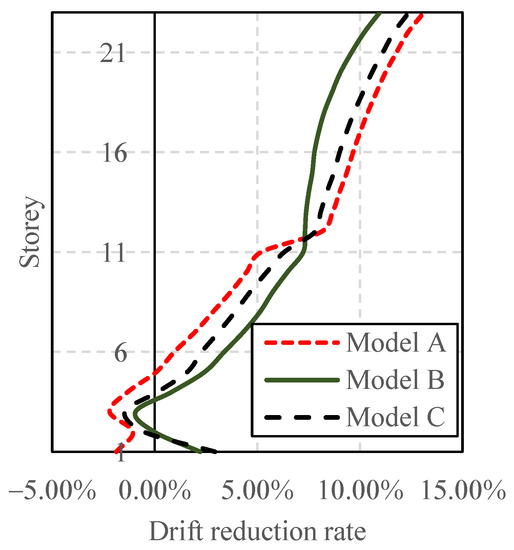
Figure 19.
Drift reduction rate of Model A, B, and C compared to the original model.
To discuss the difference between the damper placement in the same and inter-story levels, the drift reduction rate of Model B and Model C compared to Model A is given in Figure 20. The response of both the RC tower and steel podium are compared. For the RC tower with connecting dampers under maximum earthquakes, results indicate that the dampers installed at the inter-story levels are less effective in reducing the seismic response in the floors with additional dampers. However, they cause a less adverse effect on the upper floors without connecting dampers. For the steel podium, the influence is more significant, the drift of the bottom floors is reduced between 0% and 10%, but the maximum drift is amplified by at most 65% on the upper floors. Previous analytical studies have proven that the connecting damper can potentially cause an adverse effect on buildings, which has been verified herein.
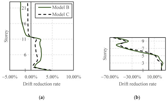
Figure 20.
Drift reduction rate of Model B and Model C compared to Model A: (a) RC tower; (b) Steel podium.
For different models under maximum considered earthquakes, the seismic input energy, kinetic energy, potential energy, modal damping energy dissipated by structural hysteretic loops (hinges and nonlinear layered shells), and energy dissipated by viscous dampers are calculated and compared. An example of the time history of seismic energy is given as an example in Figure 21a. The hinge state of a typical frame of the concrete tower is presented in Figure 21b. All the hinges occurred at the beam end within the LS (life safety) and IO (immediate occupancy) states. The columns and walls stay at the elastic stage, which presents an optimal seismic performance.
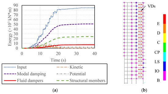
Figure 21.
Nonlinear response of Model A: (a) Energy comparison; (b) Hinge state.
The maximum value of each energy component from different models is displayed in Figure 22. The viscous dampers dissipate no energy for the original RC tower. For Model A, the dampers are installed within the tower building, and additional connecting dampers are considered in Model B and Model C. The model damping ratio is set as 5% during the nonlinear analysis, and then the overall damping ratio provided by viscous dampers is calculated by the proportion of the dissipated energy. For Model A, Model B, and Model C, the additional damping ratio is 0.50%, 0.63%, and 0.72%, respectively.
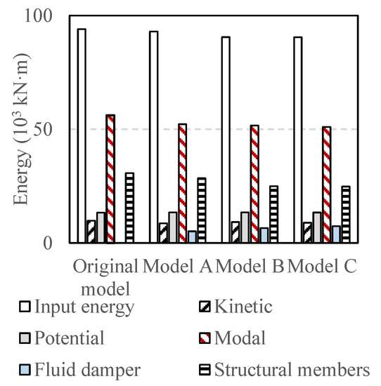
Figure 22.
Total energy comparison of different models.
The total energy dissipated by the dampers and the structural members can reflect the damper performance and the structural damage level. The total energy values are compared in Figure 23. Comparing Model A with the Original Model, the dampers within the tower can have a significant effect in dissipating motion energy and mitigating structural damage. Comparing Model B/C with Model A, in the aspect of overall energy, the connecting dampers significantly decrease the energy component of the structural members. It is also concluded that connecting dampers in Model C are slightly more efficient than in Model B.
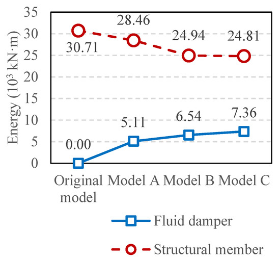
Figure 23.
Energy comparison of viscous dampers and structural members.
5. Conclusions
Analytical and numerical studies have been performed in this paper to compare the seismic mitigation effect of viscous dampers to connect two adjacent buildings. The dynamic properties of two adjacent buildings and different damper placements are discussed. In addition, Nonlinear time history (NLTH) numerical analyses for an actual engineering project under frequent and rare earthquakes are performed. The main conclusions are summarized as follows:
- (1)
- From the comparison of transmissibility curves, the connecting dampers can increase the modal damping ratio as the traditional placement of dampers within a single building. In contrast, the dampers can cause the coupled response of the adjacent building for both the podium and tower, which can potentially amplify the seismic response.
- (2)
- The analytical and numerical studies prove that the connecting dampers can significantly amplify the seismic response in the upper stories of the tower. The seismic mitigation effect is proved in the lower stories on the floors where the VDs are installed. Careful consideration is required when designing dampers to connect two buildings. The seismic performance of the upper floors should especially be guaranteed.
- (3)
- For the considered cases in this study, traditional damper placement can be more effective for seismic controlling of a single building. If dampers are designed to connect adjacent buildings due to architectural requirements or to avoid pounding, connecting the two ends of the dampers on different levels should obtain a better seismic mitigation effect under seismic input.
Author Contributions
Conceptualization, X.W.; methodology, P.C.; software, P.C.; validation, X.W.; formal analysis, P.C.; investigation, P.C.; resources, X.W.; data curation, P.C.; writing—original draft preparation, P.C.; writing—review and editing, P.C.; visualization, P.C.; supervision, X.W.; project administration, X.W.; funding acquisition, X.W. All authors have read and agreed to the published version of the manuscript.
Funding
The authors appreciate the support of the National Key R&D Program of China (2019YFC1509305) and the Fundamental Research Funds for the Central Universities (Grant No. 2022SCU12083).
Data Availability Statement
Not applicable.
Conflicts of Interest
The authors declare no conflict of interest.
References
- Zhai, C.; Jiang, S.; Li, S.; Xie, L. Dimensional analysis of earthquake-induced pounding between adjacent inelastic MDOF buildings. Earthq. Eng. Eng. Vib. 2015, 14, 295–313. [Google Scholar] [CrossRef]
- Luco, J.E.; De Barros, F.C.P. Optimal damping between two adjacent elastic structures. Earthq. Eng. Struct. D 1998, 27, 649–659. [Google Scholar] [CrossRef]
- Xu, Y.L.; He, Q.; Ko, J.M. Dynamic response of damper-connected adjacent buildings under earthquake excitation. Eng. Struct. 1999, 21, 135–148. [Google Scholar] [CrossRef]
- Zhang, W.S.; Xu, Y.L. Dynamic characteristics and seismic response of adjacent buildings linked by discrete dampers. Earthq. Eng. Struct. D 1999, 28, 1163–1185. [Google Scholar] [CrossRef]
- Tubaldi, E.; Barbato, M.; Dall’Asta, A. Performance-based seismic risk assessment for buildings equipped with linear and nonlinear viscous dampers. Eng. Struct. 2014, 78, 90–99. [Google Scholar] [CrossRef]
- Yang, Z.; Lam, E.S.S. Dynamic responses of two buildings connected by viscoelastic dampers under bidirectional earthquake excitations. Earthq. Eng. Eng. Vib. 2014, 13, 137–150. [Google Scholar] [CrossRef]
- Xu, Y.L.; Zhan, S.; Ko, J.M.; Zhang, W.S. Experimental investigation of adjacent buildings connected by viscous damper. Earthq. Eng. Struct. D 1999, 28, 609–631. [Google Scholar] [CrossRef]
- Yang, Z.; Xu, Y.L.; Lu, X.L. Experimental seismic study of adjacent buildings with viscous dampers. J. Struct. Eng. 2003, 129, 197–205. [Google Scholar] [CrossRef]
- Wu, Q.; Yan, H.; Zhu, H.; Bai, X. Shaking table test study on the seismic isolation effect of a hybrid passive control system. Measurement 2020, 164, 108125. [Google Scholar] [CrossRef]
- Tubaldi, E. Dynamic behavior of adjacent buildings connected by linear viscous/viscoelastic dampers. Struct. Control. Health Monit. 2015, 22, 1086–1102. [Google Scholar] [CrossRef]
- Patel, C.C. Random response analysis of adjacent structures connected with friction damper. Asian J. Civ. Eng. 2021, 22, 1115–1129. [Google Scholar] [CrossRef]
- Xu, L.; Cui, Y.; Wang, Z. Active tuned mass damper based vibration control for seismic excited adjacent buildings under actuator saturation. Soil Dyn. Earthq. Eng. 2020, 135, 106181. [Google Scholar] [CrossRef]
- De Souza Pippi, A.; Avila, S.M.; Doz, G. A review on the use of the inerter device in the structural coupling technique for adjacent building vibration control. Structures 2022, 42, 480–501. [Google Scholar] [CrossRef]
- Zhao, Z.; Wang, Y.; Hu, X.; Weng, D. Seismic performance upgrading of containment structures using a negative-stiffness amplification system. Eng. Struct. 2022, 262, 114394. [Google Scholar] [CrossRef]
- Bigdeli, K.; Hare, W.; Tesfamariam, S. Configuration optimization of dampers for adjacent buildings under seismic excitations. Eng. Optimiz. 2012, 44, 1491–1509. [Google Scholar] [CrossRef]
- Bigdeli, K.; Hare, W.; Nutini, J.; Tesfamariam, S. Optimizing damper connectors for adjacent buildings. Optim. Eng. 2016, 17, 47–75. [Google Scholar] [CrossRef]
- Bigdeli, K.; Hare, W.; Tesfamariam, S. Optimal design of viscous damper connectors for adjacent structures using genetic algorithm and Nelder-Mead algorithm. In Proceedings of the Active and Passive Smart Structures and Integrated Systems, San Diego, CA, USA, 27 March 2012. [Google Scholar]
- Tubaldi, E.; Gioiella, L.; Scozzese, F.; Ragni, L.; Dall’Asta, A. A design method for viscous dampers connecting adjacent structures. Front. Built Environ. 2020, 6, 25. [Google Scholar] [CrossRef]
- Palermo, M.; Silvestri, S. Damping reduction factors for adjacent buildings connected by viscous-viscous dampers. Soil Dyn. Earthq. Eng. 2020, 138, 106323. [Google Scholar] [CrossRef]
- Ou, J.; Li, H. Design approaches for active, semi-active and passive control systems based on analysis of characteristics of active control force. Earthq. Eng. Eng. Vib. 2009, 8, 493–506. [Google Scholar] [CrossRef]
- Uz, M.E.; Hadi, M.N.S. Optimal design of semi active control for adjacent buildings connected by MR damper based on integrated fuzzy logic and multi-objective genetic algorithm. Eng. Struct. 2014, 69, 135–148. [Google Scholar] [CrossRef]
- Guenidi, Z.; Abdeddaim, M.; Ounis, A.; Shrimali, M.K.; Datta, T.K. Control of adjacent buildings using shared tuned mass damper. Procedia Eng. 2017, 199, 1568–1573. [Google Scholar] [CrossRef]
- Al-Fahdawi, O.A.S.; Barroso, L.R.; Soares, R.W. Simple adaptive control method for mitigating the seismic responses of coupled adjacent buildings considering parameter variations. Eng. Struct. 2019, 186, 369–381. [Google Scholar] [CrossRef]
- Al-Fahdawei, O.F.S.; Barroso, L.R. Adaptive neuro fuzzy and simple adaptive control methods for full three-dimensional coupled buildings subjected to bi-directional seismic excitations. Eng. Struct. 2021, 231, 111798. [Google Scholar] [CrossRef]
- Karabork, T.; Aydin, E. Optimum design of viscous dampers to prevent pounding of adjacent structures. Earthq. Struct. 2019, 16, 437–453. [Google Scholar]
- Kazemi, F.; Miari, M.; Jankowski, R. Investigating the effects of structural pounding on the seismic performance of adjacent RC and steel MRFs. Bull. Earthq. Eng. 2021, 19, 317–343. [Google Scholar] [CrossRef]
- Jankowski, R.; Mahmoud, S. Linking of adjacent three-storey buildings for mitigation of structural pounding during earthquakes. Bull Earthq. Eng. 2016, 14, 3075–3097. [Google Scholar] [CrossRef]
- Kandemir-Mazanoglu, E.C.; Mazanoglu, K. An optimization study for viscous dampers between adjacent buildings. Mech. Syst. Signal Process. 2017, 89, 88–96. [Google Scholar] [CrossRef]
- Zhu, Z.; Lei, W.; Wang, Q.; Tiwari, N.; Hazra, B. Study on wind-induced vibration control of linked high-rise buildings by using TMDI. J. Wind Eng. Ind. Aerodyn. 2020, 205, 104306. [Google Scholar] [CrossRef]
- Wang, Q.; Tian, H.; Qiao, H.; Tiwari, N.D.; Wang, Q. Wind-induced vibration control and parametric optimization of connected high-rise buildings with tuned liquid-column-damper–inerter. Earthq. Struct. 2021, 226, 111352. [Google Scholar] [CrossRef]
- Ricciardelli, F.; Occhiuzzi, A.; Clemente, P. Semi-active tuned mass damper control strategy for wind-excited structures. J. Wind Eng. Ind. Aerod. 2000, 88, 57–74. [Google Scholar] [CrossRef]
- Pilarska, D.; Maleska, T. Numerical analysis of steel geodesic dome under seismic excitations. Materials 2021, 14, 4493. [Google Scholar] [CrossRef] [PubMed]
- Nair, D.; Ichihashi, K.; Terazawa, Y.; Sitler, B.; Takeuchi, T. Higer mode effects of multistorey substructures on the seismic response of double-layered steel gridshell domes. Eng. Struct. 2021, 243, 112677. [Google Scholar] [CrossRef]
- Fan, F.; Zhi, X.; Li, W. Analysis of the acceleration response spectra of single-layer spherical reticulated shell structures. Appl. Sci. 2022, 12, 2116. [Google Scholar] [CrossRef]
- Zhou, Y.; Chen, P. Investigations on a vertical isolation system with quasi-zero stiffness property. Smart Struct. Syst. 2020, 25, 543–557. [Google Scholar]
- GB 50011-2016; Chinese Standard, Code for Seismic Design of Buildings. Chinese Architecture and Building Press: Beijing, China, 2018.
Publisher’s Note: MDPI stays neutral with regard to jurisdictional claims in published maps and institutional affiliations. |
© 2022 by the authors. Licensee MDPI, Basel, Switzerland. This article is an open access article distributed under the terms and conditions of the Creative Commons Attribution (CC BY) license (https://creativecommons.org/licenses/by/4.0/).