Abstract
To promote the development of timber–steel composite (TSC) structures, this paper proposes a TSC I-beam with an I-beam as the webs, covered with a timber board on its upper and lower surfaces and bolted together; the effect of varying the ratio of the timber board thickness to I-beam on the bending performance of the TSC I-beam was investigated. Considering the same total height of the beam cross-section and the variation of timber board thickness and I-beam height, three groups of six TSC beam specimens were designed and fabricated to carry out bending load failure tests, and the effects of the variation of timber board thickness with respect to I-beam height on the failure mode, flexural load capacity, ductility, and composite degree of TSC beams were analyzed. In addition, a model for predicting the elastic ultimate bending capacity and mid-span deflection of TSC I-beams was proposed on the basis of the composite coefficient method, which avoids the need to test the joints, and the theoretical calculation results were in good agreement with the test results, which can provide a reference for the design of TSC I-beams.
1. Introduction
As a new type of structure, TSC members can combine the advantages of timber and steel and give full play to material performance. Ordinary TSC members only comprise a small amount of steel, which serves to contribute to structural strength and improve the stiffness of the timber, while the timber component mainly fulfills the role of supporting the thin-steel casing, preventing local buckling of steel; hence, the load-bearing capacity of TSC members is higher than that of pure steel members [1]. In this study, a TSC I-beam is proposed on the basis of the mechanical properties of timber with high tensile and compressive strength, as well as low shear strength along the grain, while the steel is light with high strength; therefore, with I-beams as the webs and timber boards as the upper and lower wings, using bolted connections to form a TSC I-beam makes full use of the physical and mechanical properties of timber and steel, overcoming the shortcomings of shear failure along the grain of the webs during bending of timber beams, making the flexural load capacity of the composite beam much higher than that of pure timber beams [2], which provides more possibilities for the application of timber structures in mid-rise buildings and large-span pedestrian bridges.
At present, some research progress has been made in the field of timber–steel composite beams (TSC) both in China and internationally. Wang [2] conducted a comparative study on the flexural performance of glued timber I-beams and TSC I-beams, the results of which showed that the flexural bearing capacity and ductility of the TSC 1I-beam were much greater than those of the glulam I-beam, and the brittle shear failure of the web along the grain direction caused by the low shear strength of the timber was effectively solved. Xu et al. [3] experimentally investigated the flexural resistance of two different pin-connected TSC nodes and developed a finite element model with good agreement with the experimental results for practical application. Md Saiful Islam [4] analyzed the connection capacity of a timber panel roof framing system through experimental studies and numerical simulations using screws as connectors. Loss et al. [5] designed a steel–wood composite flooring connected by shear connectors and analyzed its performance in terms of plane stiffness, load-bearing capacity, and other properties under horizontal loading through tests. Hassanieh [6] studied the short-term performance of TSC beams (flexural load carrying capacity, load–slip response, damage modes, and so on) by means of experiments and numerical simulations and found that the initial stiffness of TSC beams using bolted connections was significantly greater than that of TSC beams using screws; furthermore, TSC beams using a combination of glue and mechanical connectors exhibited full composite efficiency. Hassanieh [7] studied the effects of different shear connectors, i.e., with or without epoxy glue, or filled with cement grouting pockets, on initial stiffness, failure mode, and peak bearing capacity of TSC (cross-laminated timber (CLT)) I-beams. The composite efficiency of composite beams with different connection methods was calculated by combining the finite element model with the test results. Valipoura [8] evaluated the ductility, strength damage, and equivalent viscous damping of mechanical shear connectors in TSC beams under cyclic loading conditions using the type of shear connectors, namely, screws and/or high-strength bolts, shear connector size, and CLT board texture loading direction as parameters. Parvez Alam [9] analyzed the effects of the geometry and arrangement of steel bars within timber beams on the flexural performance of TSC beams using the method of nonlinear finite element simulations. Khan [10] proposed a C-shaped TSC beam with bolted connections in different directions (horizontal and vertical) to improve its load-carrying capacity and ductility. To date, domestic and foreign research has been carried out on the bending properties of TSC beams and pure timber beams, as well as the composite connection forms of composite beams, yielding many reliable results, which have promoted the development of TSC beams. The existing research on the bending behavior of TSC I-beams remains inadequate, while the influence of the composite ratio of cross-sectional geometry parameters of a TSC I-beam on the flexural performance of the composite beam has yet to be studied; furthermore, the actual engineering application proposed to date also lacks a relevant design basis. This study controlled the height of the TSC I-beam cross-section and changed the ratio of timber thickness to I-beam height, while the effect of the thickness ratio of the timber board with respect to the height of the I-beam on the flexural performance of the TSC I-beam was investigated using model testing. A model is proposed for the calculation of the elastic ultimate load carrying capacity of the TSC I-beam, which provides a basis for the design of the TSC I-beam in practical applications.
2. Materials and Methods
2.1. Specimens Design and Fabrication
A total of three groups (L1–L3) of TSC I-beam specimens were designed and produced, with two specimens in each group. The span, section height, width, and bolt arrangement of the three groups of beams were the same, whereas only the thickness of the upper and lower flange timber boards and the height of the I-beam varied. The beam length was 1500 mm, the calculated span was 1350 mm, and the section height and width were 150 mm and 145 mm, respectively. The thicknesses of the L1–L3 groups of specimen planks were 25 mm, 30 mm, and 35 mm, respectively, and the corresponding I-beam heights were 100 mm, 90 mm, and 80 mm, respectively. To meet the requirements of the “standard for design timber structures” [11] and “code for design of steel structures” [12], 4.8 grade 6 mm bolts were adopted for testing, and washers were fitted to the nut and surface of the timber board; four rows of bolts were used to connect the components, and the longitudinal spacing between the bolts in the middle span of the composite beam was 70 mm, the end spacing was 50 mm, the lateral spacing between the two outer rows of bolts was 35 mm, and the middle spacing was 32 mm. To prevent local buckling of the upper flange of the I-beam, specimens in groups L1 and L2 were designed for comparison in the form of one sample comprising 4 mm × 10 mm longitudinal stiffening ribs, while the other had no longitudinal ribs. Figure 1 shows the structure of the L1 group of specimens, and the detailed size parameters of the L1–L3 groups of specimens are shown in Table 1 below.
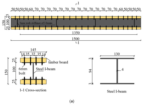
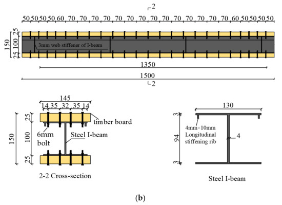
Figure 1.
Construction of specimens of group L1 (unit: mm): (a) specimens without longitudinal stiffening ribs; (b) specimens with longitudinal stiffening ribs.

Table 1.
Main design parameters of the specimen (unit: mm).
2.2. Material Properties
2.2.1. Timber Board
The timber boards were made from Northeast Hingan larch logs by grinding and polishing. The basic material properties of the timber were tested according to the methods specified in “ASTM standards” [13], and the test results were deduced according to the “Design Handbook for Timber Structures” [14]. The results are shown in Table 2.
Table 2.
Basic mechanical parameters of timber (unit: MPa).
2.2.2. Steel and Bolts
The steel adopted for the I-beam was Q235 hot-rolled profiles, and the bolts were standard 4.8 grade 6 mm ones. The mechanical properties of the steel are shown in Table 3, while the mechanical properties of the bolts are shown in Table 4.
Table 3.
Basic mechanical parameters of steel (unit: MPa).
Table 4.
Basic mechanical parameters of bolt (unit: MPa).
2.3. Test Method
This test was carried out in the laboratory of the School of Civil Engineering, Central South University of Forestry and Technology, Hunan, China. The loading device used was a 100 t reaction force frame with a 100 t hydraulic jack (Manufactured by Xiangtan Zhaoyuan Mechanical & Electrical Co.), and a load sensor was utilized to measure and read the load. The specific loading device layout is shown in Figure 2a. Referring to the Eurocode for timber structures [15], the loading method of three equal points was adopted, and the preloading was set to 20% of the estimated bearing capacity prior to formal loading to verify that the device was operating normally. The formal loading method adopted was that of step-by-step loading. When the load was 0–40 kN, the load increment at each stage was 5 kN, which was maintained for 1 min; above 40 kN, the load increment at each stage was 3 kN, which was maintained for 30 s. The test ended when failure occurred or when the load was greatly reduced.
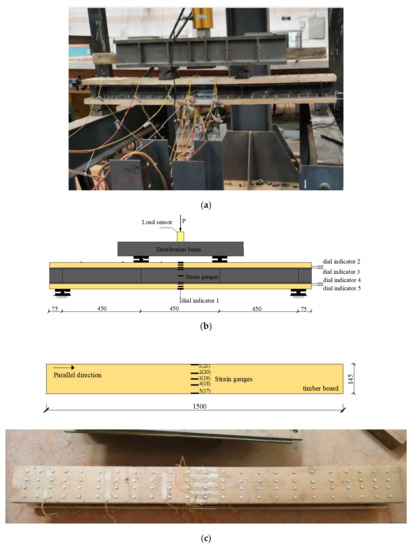
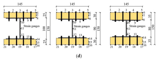
Figure 2.
Loading device and layout of measuring points (unit: mm): (a) photo of the loading device; (b) loading device and dial indicator arrangement; (c) arrangement of strain gauges on the top and bottom boards of specimens; (d) arrangement of strain measurement points for mid-span sections.
A DH3861 static strain acquisition system and dial indicator were used to measure and read the strain and displacement of the specimen during the loading process. The dial indicator arrangement is shown in Figure 2b; a dial indicator was fitted at the bottom of the mid-span of the beam to measure the mid-span deflection of the beam, and four dial indicators were arranged on the timber boards and I-beam of the upper and lower flanges, at the end of the beam. The dial indicators measured the relative slip between the upper and lower flange timber boards and the I-beam. The strain disposition scheme for each group of specimens was as follows: five longitudinal strain gauges were fitted to the top and bottom timber boards of the beam mid-span to test the normal strain (Figure 2c). On the mid-span section of the beam, the upper and lower three longitudinal strain gauges were evenly positioned along the height orientation of the flange timber boards, and five longitudinal strain gauges were set along the height orientation of the I-beam to measure the normal strain (Figure 2d).
2.4. Theoretical Method
2.4.1. Equal Energy Method
The yield point is a key performance point in the study and design of engineering structures and is a key factor in measuring the ductility of a structure. According to the studies of Park et al. [16] and Feng et al. [17], to define the yield point, the equal energy method was adopted in this study to define the yield displacement (Figure 3), and the ductility coefficient of its deformation index was calculated using the following formulas:
where is the value of the deflection corresponding to the test ultimate load , is the value of the deflection corresponding to the test yield load , and is the area of the trapezoid OBCD.
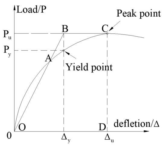
Figure 3.
Equal energy method (derived from [17]).
2.4.2. Composite Coefficient Method
The TSC beams with a partial shear connection slip at the intersection of the timber board and steel beam during bending and no longer satisfy the flat section assumption. Therefore, in order to predict the deflection and flexural load capacity of TSC beams in normal use, following the research of Jingquan Wang et al. [18], this paper uses the combined coefficient method to calculate the flexural stiffness of TSC beams while considering the slip effect. The calculation method and formula of the elastic limit flexural bearing capacity of the composite beam are proposed, which satisfy the following basic assumptions: (1) both timber and steel are ideal linear elastic bodies; (2) a bolt offers a good anti-lifting effect, and the timber board has the same curvature as the I-beam; (3) after slip occurs, both the timber board and the I-beam satisfy the assumption of a plane section; (4) the flexural rigidity of the partially shear-connected composite beam lies between the fully composite connection and the non-composite connection.
The composite coefficient method is an interpolation method based on the case of shear connectors, and the expression of its effective stiffness is as follows:
where is the elastic modulus of the timber, as shown in Table 2, is the moment of inertia of the upper and lower timber board sections, is the modulus of elasticity of steel as shown in Table 3, Is is the moment of inertia of the I-beam section, and is the composite coefficient.
- (1)
- No-shear connection composite coefficients
The composite beam without combined action has no shear force transmission at the composite interface, and both the timber board and the I-beam are bent independently; hence, the composite coefficient can be considered to be 0 ().
- (2)
- Full-shear connection composite coefficients
The effective stiffness of the fully shear-connected composite beam is calculated as follows according to the equivalent section method [18]:
The full shear connection composite coefficient is
- (3)
- Composite coefficients of partial shear connections
The degree of composite connection is related to the shear stiffness of the shear connectors, and the shear stiffness is in turn related to the number of bolts and the cross-sectional area of the shear connectors. Following William’s [19] and Nie’s [20] research, the square-root interpolation method of the ratio of the number of bolts (single bolt cross-sectional area and material properties are the same) was used to calculate the composite coefficient of partial shear connections in this study.
where is calculated according to the following formulas:
where and are the number of bolts for full shear connections and partial shear connections, respectively, is the composite beam interface shear force, is the ultimate shear design bearing capacity of a single bolt, is the area of the cross-section over the width of the shear plane of the timber board (), is the cross-sectional area of the I-beam flange (), is the bolt diameter, and is the design value of the shear strength of the bolt, shown in Table 4.
- (4)
- Calculation model of elastic limit state load-carrying capacity and mid-span deflection
Composite beams with partial shear connections produce slip at their interface [20,21,22,23], where the stresses on the surface of the timber board and those on the surface of the I-beam are not equal, resulting in different strains on the interfacing upper and lower surfaces, which can be defined as slip strain. Therefore, the strain of a partial shear connection can be divided into the strain generated by the full shear connection and the superposition of the strain generated by the slip, the calculation model of which is shown in Figure 4, where and are the cross-sectional areas of the timber board and the cross-sectional area of the I-beam, respectively, , , and are the timber board slip strain, I-beam slip strain, and total slip strain, respectively, and is the yield strain of the I-beam. The ultimate elastic flexural load capacity of the partially composite beam is
where is the flexural capacity of fully composite beams, is the additional bending moment caused by the slip strain of the timber board, is the additional bending moment due to slip strain in the I-beam, and is the additional bending moment due to slip strain.
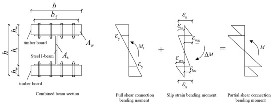
Figure 4.
Model for calculating the ultimate elastic flexural load capacity of a partially composite beam.
According to Nie’s definition of slip strain [20,24,25], if is the additional curvature generated by the slip strain, the expression for the slip strain can be derived as follows:
The slip strains of the timber board and the I-beam are
According to Figure 4, the additional bending moments generated by the slip strain of the timber and the I-beam are
Combining Equations (11)–(17) yields
Therefore, the equation for the elastic flexural load capacity of the partially shear- connected composite beam is as follows:
In this case, the moment of the fully shear-connected composite beam can be calculated using the converted section method as follows:
where is the yield strength of the steel, is the ratio of the modulus of elasticity of steel to the modulus of elasticity of timber, and .
The test value of the elastic ultimate bending moment of the combined beam can be calculated according to the following formula:
where is the test yield load of the composite beam, and is the distance between the loading point and the proximal support.
On the basis of the research of Ji [26] and Wang [27], the composite beam deflection in the normal use phase can be carried out according to the method of structural mechanics and calculated according to the following equations:
where is the theoretical yield load of the combined beam, is the calculated span of the combined beam (see Table 1), and is the elastic limit theoretical bending moment value.
3. Results and Discussion
3.1. Analysis of Failure Mode and Failure Mechanism
The failure modes of each group of specimens are shown in Figure 5. When the L1 group of specimens was loaded to 85% of the ultimate load, short longitudinal cracks appeared in the bending shear section of the top timber board (Figure 5a,b). When the ultimate load was reached, the timber fibers of the bottom board were pulled off (Figure 5c,d), while local buckling of the upper flange of the I-beam occurred at the loading point of the specimen (L1-1) without longitudinal stiffeners ribs (Figure 5e).
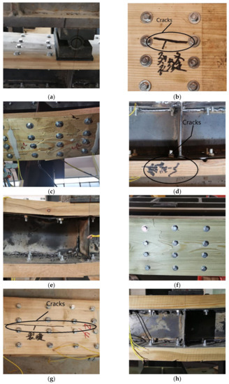
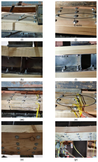
Figure 5.
Failure mode of specimens in groups L1–L3: (a) crack in L1-1 specimen top board; (b) crack in L1-2 specimen top board; (c) L1-1 specimen base board failed in tension; (d) L1-2 specimen base board failed in tension; (e) L1-1 specimen steel flange flexure; (f) L2-1 specimen base board failed in tension; (g) L2-2 specimen base board failed in tension; (h) L2-1 specimen steel flange with no buckling; (i) L3-1 specimen cracking in the bending and shearing section of the top board; (j) L3-2 specimen cracking in the bending and shearing section of the top board; (k) L3-1 specimen top board partial crush and steel flange buckling; (l) L3-2 specimen top board partial crush and steel flange buckling; (m) L3-1 specimen top board cracked exclusively in the curved section; (n) L3-2 specimen top board cracked exclusively in the curved section; (o) L3-1 specimen base board failed in tension; (p) L3-2 specimen base board failed in tension.
When the L2 group of specimens was loaded to about 85% of the ultimate load, there was a continuous sound, but there was no sign of failure; when the L2-1 specimen was loaded to the ultimate load, the timber fibers at the bottom of the L2-1 specimen were pulled off (Figure 5f), longitudinal cracks appeared on the bottom board of the L2-2 specimen (Figure 5g), and the L2-1 specimen without steel flange no buckled (Figure 5h).
When the specimens in group L3 were loaded to 80% of the ultimate load, small longitudinal cracks appeared in the bending shear section of the top board (Figure 5i,j), with local crushing of the timber flange below the loading point and local buckling of the steel flange (Figure 5k,l). When the loading was continued to the ultimate load, longitudinal cracks appeared exclusively in the bending section of the top board and joined the longitudinal cracks in the bending shear section to form one long crack (Figure 5m,n), and the timber of the bottom board was pulled off and failed (Figure 5o,p).
Failure mode: The TSC beams in this test showed two failure modes (Mode I and II) due to the change in the ratio of the timber board thickness to the height of the I-beam. The failures of the L1 group specimens with thinner timber boards and the L3 group specimens with thicker timber boards were ductile failures (Mode I), which occurred during the bending loading process. First, the timber of the top board of the span split and flexed locally; then, when the ultimate load was reached, the timber of the bottom board of the span was pulled off and failed, while the upper flange of the I-beam without longitudinal stiffening ribs flexed locally. The failure of the L2 group of specimens with moderate timber board thickness was a brittle failure (Mode II). No obvious failures were observed during the bending loading; however, when loaded to the ultimate load, the bottom board timber was pulled off and failed along the grain, while the upper flange of the I-beam without longitudinal ribs did not incur any local compression flexure.
Failure mechanism: When the composite beam was bent, the top timber board was under compression, and the bottom timber board was under tension. When the bending moment was large, the timber of the top board at the mid-span generated a large transverse tensile force due to longitudinal compression, which caused the transverse grain of the timber to crack under tension and form longitudinal cracks, i.e., local splitting failure, accompanied by local crushing along the parallel grain. Then, as the load and section bending moment increased further, the local longitudinal tensile stress in the bottom board exceeded the ultimate tensile strength of the timber along the grain, and the timber was pulled off; at the same time, the increase in compressive stress in the top board led to local compression buckling of the upper flange of the I-beam without the longitudinal ribs. The TSC beams in this test first failed due to compression in the top timber board and secondly due to tension in the bottom timber board, which allowed full play to the tensile and compressive strengths of the timber and showed that the beams were combined in a scientifically sound form.
3.2. Load–Mid-Span Deflection
The load–mid-span deflection curves of each group of specimens are shown in Figure 6. Each group of specimens exhibited ideal elastic–plastic behavior, and the slopes of the same group of specimens were basically the same in the elastic stage. The mechanical properties of each specimen based on the test results are shown in Table 5 below.
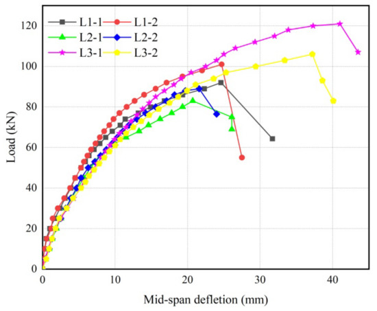
Figure 6.
Load–span deflection curve.
Table 5.
Main mechanical properties of specimens.
As can be seen from Table 5, the ultimate bearing capacity of the L3 group of specimens was the highest, of the L1 group was the second highest, and of the L2 group was the lowest. The bearing capacity of the L3 group (taken as the average of the two specimens 113 kN) was 37% higher than that of the L2-1 specimen, the bearing capacity of the L1-1 specimen was 10.8% higher than that of the L2-1 specimen, the ductility coefficient of the L1-1 specimen was 26.5% higher than that of the L2-1 specimen, and the ductility coefficient of the L3 group (taken as the average of the two specimens 2.04) was 38.1% higher than that of the L2-1 specimen. This indicated that the change in the ratio of the timber board thickness to I-beam height had a greater influence on the mechanical properties such as flexural load capacity and ductility, which, in the authors’ view, was because a composite beam with a better composite ratio can make full use of the mechanical properties of timber and steel. The addition of longitudinal stiffening ribs increased the load-carrying capacity of the composite beams by 8.9% and 6.7% respectively, but the effect on the ductility was smaller due to the reduced height of the longitudinal stiffening ribs.
3.3. Load–Slip Response
Since the shear connectors were flexible, they deformed to a certain extent when subjected to shear force, resulting in relative slippage of each part of the composite members, leading to a decrease in stiffness of the composite members. The composite beams in this test produced a slip pattern at the end, as shown in Figure 7. The upper I-beam flange slip was inward relative to the top timber board, and the lower I-beam flange slip was outward relative to the bottom timber board. The load–end slip curves for the specimens are shown in Figure 8, where and represent the upper flange slip and lower flange slip, respectively, with positive values indicating I-beam outreach and negative values indicating I-beam internal shrinkage.
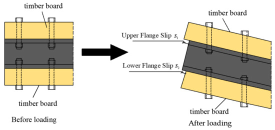
Figure 7.
Slip diagram.
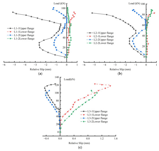
Figure 8.
Load–slip response; (a) L1 group; (b) L2 group; (c) L3 group.
It can be seen from Figure 8 that the slip of the upper and lower flanges of each group of specimens basically increased with increased loading. In particular, the slip of the upper flange of the specimens in groups L1 and L2 increased with the load at the beginning of loading; however, when loaded to 30–40% of the ultimate load, the slip decreased with the increase in load before increasing rapidly again. This was hypothesized to be because the compression deformation of the I-beam flange was larger than that of the timber board at the initial stage of loading, when the bolts were in contact with the whole wall of the I-beam flange. The compression deformation of the I-beam flange was, thus, blocked by the bolts, and its slip reduced, until the entire wall of the timber board made contact with the bolts, and the relative slip between the two began to increase with the increased loading. Table 6 shows the maximum slip values of the upper and lower flanges of each group of specimens, which were essentially less than 1.5 mm. However, the slippage of the upper flange of the L1-1 and L2-1 specimens reached 5.14 mm and 5.2 mm, respectively, which, in the authors’ view, was because the top timber board of these two specimens was relatively thin, and the upper flange of the I-beam was devoid of any longitudinal stiffening ribs. The upper edge of the I-beam had sustained a relatively large deformation under compression, resulting in a larger slip; the top timber boards of the L3 group of specimens was relatively thick, and the compression deformation of the timber board was greater. The L1-2 and L2-2 specimens comprised longitudinal stiffening ribs on the upper edge of the I-beam, which reduced the compression and deformation of the I-beams, thus resulting in smaller slips of under 1.5 mm in both instances.
Table 6.
Relative slip values for TSC beams.
3.4. The Normal Strain of the Mid-Span Section Was Distributed along the Height Orientation
Figure 9 shows the distribution of the normal strain in the mid-span section of each specimen in the height orientation at different loading stages. It can be seen from the figure that, when loaded to 25% of the ultimate load, due to the friction at the timber–steel interface, the gap between the bolt rod and the overall wall remained unchanged, the relative slip between timber boards and I-beam was small, and the overall bending deformation (strain) of the composite beam basically satisfied the assumption of plane section. When the shear force exceeded the maximum friction force between the boards with increasing loading, relative slip occurred between the boards, such that the overall deformation of the composite beam no longer met the assumption of the plane section, but the respective strains of the upper and lower timber boards and I-beam satisfied the plane section assumption.
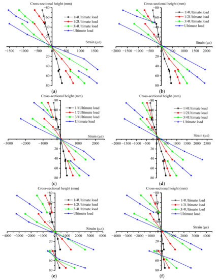
Figure 9.
Normal strain diagram for mid-span section: (a) L1-1; (b) L1-2; (c) L2-1; (d) L2-2; (e) L3-1; (f) L3-2.
Figure 10 is a schematic diagram of the bending deformation of the composite beam, divided into three cases: completely rigid connection (Figure 10b), strong composite connection (Figure 10c), and weak composite connection (Figure 10d), where is the compressive strain of the timber board, is the compressive strain of the I-beam, is the tensile strain of the timber board, and is the tensile strain of the I-beam. Due to the slippage at the timber–steel interface, the cross-sectional strain of each group of specimens failed to reach a rigid connection state; the L1 and L2 groups of specimens belonged to a strong composite connection category, where, under the ultimate load, the upper flange timber boards were completely compressed, and the bottom timber boards were completely tensioned. Under ultimate load, the upper flange timber boards of the L3 group of specimens were fully compressed, thus forming a strong, combined joint, while the lower flange timber boards were tensioned at the bottom and compressed at the top, thus making for a weak combined joint. In summary, when the bolt arrangement parameters were the same and the thickness of the timber boards was thicker, the connection performance was also found to be worse, which the authors ascribed to the fact that, as the thickness of the timber board increased, the bearing area of the bolts also kept increasing, indicating that the shear stiffness of the bolts was related not only to the shear modulus, but also to the shear area.
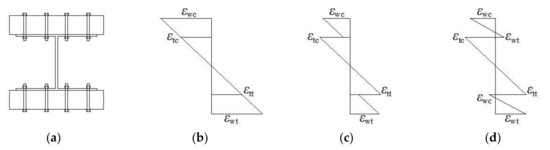
Figure 10.
Schematic diagram of normal strain in the cross-section of the composite beam: (a) composite beam; (b) fully rigid connection; (c) strong composite connection; (d) weak composite connection.
The compressive failure of timber has an obvious yield stage, while its tensile failure is a typical brittle type failure [28,29,30]. It can be seen from Table 2 that the compressive strength along the grain of the timber was 26.16 MPa, the tensile strength along the grain was 20.75 MPa, the yield strength of the steel was 235 MPa, the yield compressive strain along the grain of the timber in this study was 1963 uε, the ultimate tensile strain along the grain was 1557 uε, and the yield strain of the steel was 1140 uε. It can be seen from Figure 8 that, when the ultimate load was reached, the maximum along-grain compressive strain of the upper flange timber boards of the L1 and L2 groups was about 1600 uε, which is about 82% of the theoretical yield strain. At that point, the timber boards had been compressed and undergone local plastic deformation, with local splitting failure occurring in the L1 group of specimens, which was due to a certain deviation between the compressive failure performance of the entire timber board member and that of the standard specimen in the material property test. The compressive strain along the grain of the L3 group of specimens exceeded 3000 uε, which far exceeded the theoretical yield strain; thus, long splitting cracks along the grain direction of the timber boards occurred. The tensile strain along the grain was exceeded the ultimate tensile strain along the grain when the lower flange of the L1–L3 groups of specimens failed. When the ultimate load was reached, the maximum tensile and compressive strain of the L1 and L2 group I-beams was about 1600 uε, while the maximum tensile and compressive strain of L3 group I-beams exceeded 2500 uε, which exceeded the yield strain of steel. Therefore, when the ultimate load was reached, the I-beams of each group of specimens entered the flow amplitude stage.
3.5. Lateral Distribution of Normal Strain in Mid-Span Timber Board
Figure 11 illustrates the distribution law of the normal strain of the upper and lower timber boards in the middle span of each group of specimens along the width direction (transverse plane). In the initial stage of loading, the lateral distribution of normal strain was relatively uniform, and, as the load increased, the distribution of normal strain gradually became uneven. Among other findings, the difference in strain on both sides of the lower flange of the L1-2 specimen and the upper flange of the L3-1 specimen was greater, as a result of material defects such as wood knots and twill, and the side incurring the greater strain was that close to sites responsible for the timber board failure. In general, the lateral distribution of the normal strain of the upper and lower timber board was relatively uniform, indicating that the shear lag effect was not obvious. This was because the width of the I-beam flange was essentially the same as that of the timber flange, such that the shear stress was mainly borne by the steel I-beam, while the shear stress borne by the timber board was low. This also indicated that the change in ratio of the composite beam timber board thickness to I-beam height composite in this study had a small effect on the shear lag effect of the composite beam.
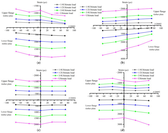
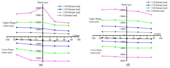
Figure 11.
Lateral distribution of normal strains in the upper and lower timber boards of the mid-span section: (a) L1-1; (b) L1-2; (c) L2-1; (d) L2-2; (e) L3-1; (f) L3-2.
3.6. Comparison of Experimental and Theoretical Calculations
According to the composite coefficient method, the composite coefficients for full and partial shear connections and their flexural stiffness could be obtained (Table 7).
Table 7.
Composite coefficients and flexural stiffness of composite beams.
Table 8 and Table 9 present the results of the comparison between the ultimate theoretical elastic bending moment values and mid-span deflection values obtained according to the bending capacity model proposed by the composite coefficient method and the test values, where the test values were calculated according to Equations (22)–(24). As can be seen from Table 8 and Table 9, the results calculated by the composite coefficient method were in good agreement with the test values; therefore, the composite coefficient method can reliably be used to calculate the ultimate elastic bearing capacity and mid-span deflection of TSC I-beams.
Table 8.
Comparison of elastic ultimate theoretical bending moment values with test values.
Table 9.
Comparison of elastic limit theoretical deflection values with test values.
4. Conclusions
In this study, three sets of combined timber-steel I-beams of equal cross-sectional height and different timber board thickness were tested using the method of trisection point loading to investigate the effects of the ratio of timber board thickness to I-beam height on their bending performance, and a theoretical analysis was carried out, from which the following conclusions were drawn:
- (1)
- The timber–steel composite I-beam was ultimately failed by tension in the lower flange timber board; two sets of specimens with timber boards thicknesses of 25 mm and 35 mm incurred a ductile failure, whereby the upper flange timber was partially split and buckled, while the bottom timber sustained a tensile failure along the timber grain. At the same time, local buckling occurred on the upper flange of the I-beam devoid of longitudinal stiffener ribs; the specimens with timber boards thickness of 30 mm presented a brittle failure, where only the bottom timber was fractured along the grain, and there was no local buckling on the upper flange of the I-beam without longitudinal stiffeners ribs. This was due to the different combinations of timber board thickness and I-beam height, which were subject to different bending moments.
- (2)
- The application of I-beams in TSC I-beams overcame the shortcomings of the weak shear resistance of timber, which were ultimately susceptible to tensile and compressive failures only, whilst giving full play to the tensile and compressive properties of timber, indicating that the TSC I-beam proposed in this study was a reasonable combination.
- (3)
- The bending properties of specimens with timber board thicknesses of 25 mm and 35 mms were greater than those of the specimens with timber board thickness of 30 mm, which was hypothesized to be due to their better composite ratio of the thickness of the timber boards and the height of I-beam. It was demonstrated that an improved composite ratio enabled the timber–steel composite I-beam better to give full play to the physical and mechanical properties of timber and steel, resulting in a higher bearing capacity of the composite beam.
- (4)
- In this study, the calculation model of the flexural bearing capacity of the timber–steel composite beam at the elastic limit state was proposed on the basis of the composite coefficient method. The theoretical values calculated by the composite coefficient method proved to be in good agreement with the experimental values. This confirms that this theoretical method can reliably be used for designing an actual construction material project and provides a verifiable reference.
Author Contributions
Conceptualization, J.W. and J.L.; methodology, J.W. and J.L.; software, J.L.; validation, R.L., L.C. and W.L.; formal analysis, J.L.; resources, J.W.; data curation, J.L.; writing—original draft preparation, J.L.; writing—review, J.W.; visualization, J.L.; supervision, J.W.; project administration, J.W.; funding acquisition, J.W. All authors have read and agreed to the published version of the manuscript.
Funding
This work was supported by Central South University of Forestry and Technology (Grant no. 9010263203077).
Institutional Review Board Statement
Not applicable.
Informed Consent Statement
Not applicable.
Data Availability Statement
All data, models, and code generated or used in this study are available upon request from the corresponding author.
Conflicts of Interest
The authors declare no conflict of interest.
References
- Duan, S.W.; Zhou, W.Z. Experimental Study on the Bending Behavior of Steel-Wood Composite Beams. Adv. Civ. Eng. 2021, 2021, 1315849. [Google Scholar] [CrossRef]
- Wang, J.J.; Lu, Y. Comparative study on flexural behavior of steel–timber composite beams and glued timber I-beams. J. Eng. Sci. Technol. Rev. 2020, 13, 175–186. [Google Scholar] [CrossRef]
- Xu, B.H.; Bouchaïr, A. Mechanical Behavior and Modeling of Dowelled Steel-to-Timber Moment-Resisting Connections. J. Struct. Eng. 2015, 141, 04014165. [Google Scholar] [CrossRef]
- Islam, M.S.; Chui, Y.H.; Altaf, M.S. Design and Experimental Analysis of Connections for a Panelized Wood Frame Roof System. Buildings 2022, 12, 847. [Google Scholar] [CrossRef]
- Cristiano, L.; Andrea, F. Experimental investigation on in-plane stiffness and strength ofinnovative steel-timber hybrid floor diaphragms. Eng. Struct. 2017, 138, 229–244. [Google Scholar] [CrossRef]
- Hassanieh, A.; Valipour, H.R. Experimental and numerical study of steel-timber composite (STC) beams. J. Constr. Steel Res. 2016, 122, 367–378. [Google Scholar] [CrossRef]
- Hassanieh, A.; Valipour, H.R. Experimental and numerical investigation of short-term behaviour of CLT-steel composite beams. Eng. Struct. 2017, 144, 43–57. [Google Scholar] [CrossRef]
- Ataei, A.; Chiniforush, A.A.; Bradford, M.; Valipour, H. Cyclic behaviour of bolt and screw shear connectors in steel-timber composite (STC) beams. J. Constr. Steel Res. 2019, 161, 328–340. [Google Scholar] [CrossRef]
- Alam, P.; Ansell, M. Effects of Reinforcement Geometry on Strength and Stiffness in Adhesively Bonded Steel-Timber Flexural Beams. Buildings 2012, 2, 231–244. [Google Scholar] [CrossRef] [Green Version]
- Khan, M.S.; Prof, N.S. Timber-Steel-Composite Beams for Framed Structure. Int. J. Eng. Res. Technol. 2019, 8, 1330–1335. [Google Scholar]
- GB 50005-2017; Standard for Design of Timber Strutures. Ministry of Housing and Urban-Rural Development of the People’s Republic of China: Beijing, China, 2017; pp. 41–60.
- GB 50017-2017; Code for Design of Steel Structures. Ministry of Housing and Urban-Rural Development of the People’s Republic of China: Beijing, China, 2017; pp. 73–92.
- (2007)D143-94 [S]; Standard Test Methods for Small Clear Specimens of Timber. ASTM: West Conshohocken, PA, USA, 2007.
- Design Handbook for Timber Structures Editorial Committee. Design Handbook for Timber Structures; Architecture & Building Press: Beijing, China, 2005; pp. 43–48. [Google Scholar]
- Part 1.1: General rules and rules for buildings. In DD ENV1995-1-1. Eurocode 5: Design of Timber Structures; British Standards Institution: London, UK, 1994.
- Park, R. State of the art report ductility evaluation from laboratory and analytical testing. In Proceedings of the Ninth World Conference on Earthquake Engineering, Tokyo, Japan, 2–9 August 1988. [Google Scholar]
- Feng, P.; Qiang, H.L. Discussion and definition on yield points of materies, members and structures. Eng. Mech. 2017, 34, 36–46. [Google Scholar] [CrossRef]
- Wang, J.Q.; Lv, Z.T. Consistency factor method for calculating deformation of composite steel-concrete girders with partial shear connection. J. Southeast Univ. (Nat. Sci. Ed.) 2005, 35 (Suppl. S1), 5–10. [Google Scholar]
- William, S.T. LRFD Steel Design, 3rd ed.; Thomson Brooks/Cole: San Francisco, CA, USA, 2003; pp. 436–484. [Google Scholar]
- Nie, J.G.; Cai, C.S. Steel-concrete composite beams considering shear slip effects. J. Struct. Eng. 2003, 129, 495–506. [Google Scholar] [CrossRef] [Green Version]
- Lam, D.; El-Lobody, E. Behavior of headed stud shear connectors in composite beam. J. Struct. Eng. 2005, 131, 96–107. [Google Scholar] [CrossRef]
- Gutkowski, R.; Brown, K. Laboratory tests of composite wood-concrete beams. Constr. Build. Mater. 2008, 22, 1059–1066. [Google Scholar] [CrossRef]
- Tao, H.T.; Yang, H.F. Mechanical behavior of crossed inclined coach screw shear connections for prefabricated timber-concrete composite structures. J. Build. Struct. 2022, 43, 164–174. [Google Scholar] [CrossRef]
- Nie, J.G.; Shen, J.M. A general formula for predicting the deflection of simply supported composite steel-concrete beams with the consideration of slip effect. Eng. Mech. 1994, 11, 21–27. [Google Scholar]
- Nie, J.G.; Shen, J.M. A reduced rigidity method for calculation deformation of composite steel concrete beams. Chin. Civ. Eng. J. 1995, 28, 11–17. [Google Scholar]
- Ji, W.; Sun, B. Calculation and Analysis of Deflection for Steel-concrete Composite Girder under Long-term Loads. J. Hunan Univ. (Nat. Sci.) 2021, 48, 51–60. [Google Scholar]
- Wang, S.H.; Tong, G.S. Reduced stiffness of composite beams considering slip and shear deformation of steel. J. Constr. Steel Res. 2017, 131, 19–29. [Google Scholar] [CrossRef]
- Malhotra, S.K.; Bazan, I.M.M. Ultimate bending strength theory for timber beams. Wood Sci. 1980, 13, 50–63. [Google Scholar] [CrossRef]
- Xu, B.H.; Cai, J. State-of-the-art in strength criteria for wood. Chin. Civ. Eng. J. 2015, 48, 64–73. [Google Scholar]
- Fernonow, B.E.; Neely, S.T. Progress in Timber Physics; Forest Products Laboratory (US), United States Forest Service: Washington, DC, USA, 1898; pp. 13–17. [Google Scholar]
Publisher’s Note: MDPI stays neutral with regard to jurisdictional claims in published maps and institutional affiliations. |
© 2022 by the authors. Licensee MDPI, Basel, Switzerland. This article is an open access article distributed under the terms and conditions of the Creative Commons Attribution (CC BY) license (https://creativecommons.org/licenses/by/4.0/).