Article

Experimental Investigation on the Response of Elliptical CFT Columns Subjected to Lateral Impact Loading

Department of Civil Engineering, Foshan University, Foshan 528000, China
*
Author to whom correspondence should be addressed.
Buildings 2022, 12(11), 1847; https://doi.org/10.3390/buildings12111847
Submission received: 24 September 2022 / Revised: 24 October 2022 / Accepted: 26 October 2022 / Published: 2 November 2022

Abstract

:
This study reports an experimental investigation on the impact behavior of elliptical concrete-filled steel tubular (CFT) columns subjected to lateral loading. A total of five CFT columns, including one circular cross-section and four elliptical cross-sections, were tested using a horizontal-impact-testing system. The influences of the impact velocity, the impact times, and the cross-section geometry on the dynamic response of the elliptical CFT columns were analyzed. The experimental results have shown that the specimens withstood the global displacements without the buckling of the steel tubes. The strain rates of the steel tubes in this paper were small. The impact velocity had significant influences on the impact load-time histories and energy absorption. Meanwhile, the impact times had little influence on the impact force and displacement at the same impact velocity. Circular CFT columns have the highest ductility and impact-energy-absorption capacity. Based on the finite element analysis software ABAQUS, the finite element models of the elliptical CFT columns under impact loads were established. The simulation results were in good agreement with the experimental results. Finally, the mechanical mechanism of the elliptical CFT columns under lateral impact was analyzed by the finite element model.

Graphical Abstract

1. Introduction

Over the past few decades, due to the development of transportation infrastructure and the increase of traffic, more attention has been drawn to the evaluation of bridge structures or buildings against lateral impact loads such as collisions or terrorist bombings [1]. Generally, these collisions generate a high force applied over a very short period of time, which may cause catastrophic consequences on human life and infrastructure systems [2]. Conventional structures are usually not designed to resist impact loads, and the magnitudes of impact loads are significantly higher than the design loads; therefore, conventional structures are more susceptible to damage from impact scenarios. It is worth noting that understanding the impact response of structural members can provide the solution to ensure the safety of structures.
Concrete-filled steel tubular (CFT) columns are widely used in construction due to their improved capacity and ductility. To date, the performances of standard cross-section shaped (circular, square, or rectangular) CFT columns have been investigated by various researchers [3,4,5,6,7]; however, the elliptical shape has been recently introduced to structural engineering due to their aesthetic appearance and structural efficiency. Interestingly, few researchers have conducted the experiment on the elliptical CFT columns. It was confirmed that an equivalent rectangular CFT column could be reasonably proposed to derive the capacity of an elliptical CFT column [8]. Yang et al. [9] gave the design recommendations for concrete-filled elliptical hollow sections based on the experimental investigation. More recently, Mahgub et al. [10] carried out an experimental study on the axial compressive behavior of self-compacting concrete. Cai et al. [11] found that the compressive resistance predictions of elliptical CFT stub columns from the current international design specifications were overall conservative. Recently, Ipek et al. [12] presented an investigation on the axial compressive performance of elliptical concrete-filled double-skin steel tubular columns. Additionally, the local buckling of CFT columns was studied based on the refined model [13] or the elastic behavior [14]. Unfortunately, there is a paucity of literature on the investigation of the behaviors of the elliptical CFT columns under lateral impact loads.
Apart from studies on the static behaviors of columns, the knowledge of dynamic behaviors under lateral impact loads is still relatively rare. The vertical drop hammer impact system was commonly adopted to assess the impact load on the horizontally installed specimens [15]. Remennikov et al. [16] found that the square CFT column had high-impact resistance and energy absorption capacity by conducting the instrumented drop hammer tests. Wang et al. [17] reported that the axial-load level had significant effects on the lateral deflections and the impact force of circular CFT members subjected to the lateral impact loads. Yousuf et al. [18] investigated the behavior of hollow and concrete-filled mild and stainless steel columns with the axial load from the transverse impact loading by an instrumented drop-weight impact facility. Yang et al. [19] presented the experimental and numerical results of square recycled aggregate CFT members under lateral impact loading. Thus, the majority of the available experimental tests were performed on horizontal elements featuring beam characteristics using drop-weight impact facilities. Due to the gravity influence, the drop-weight impact facilities cannot adequately reproduce the rebound conditions.
The pioneer experimental tests were carried out by Popp, who applied a full-scale truck collision on the reinforced-concrete columns. They proposed that the rise time to the peak load was in the order of magnitude of 10−1 s, which very differed from static conditions [20]. Chen et al. [20] reported the impact responses and damage characteristics of full-scale RC piers in actual truck collision tests. Although using full-scale vehicle impact tests can provide the actual impact process, they are not commonly adopted due to the tests being expensive and time-consuming. Some researchers developed novel facilities to feature the columns real characteristics under lateral impact loads in the laboratory. Aghdamy et al. [21] adopted an innovative instrumented horizontal-impact-testing system to apply lateral impact loads on the axially-loaded concrete-filled double-skin tube columns. In this approach, the column was located in the horizontal direction while the impact direction was vertical on the column. Other tests were performed on the circular reinforced-concrete piers [22] or precast segmental columns [23] by the pendulum impact test system in which an impactor can swing to impact. Recently, Feng [24] reported an experimental test using an impact test bench to understand the continuous lateral impact resistance of cantilever square CFST columns. Demartino et al. [25] used a horizontal collision facility, in which a test truck was used to reproduce the impact, to apply the lateral impact loading on the vertical circular RC columns. Ye et al. [26] presented an experimental study on 15 square RC columns under horizontal impact loading. Some researchers have studied structural members under repeated impact loads [27,28]; therefore, it is necessary to study the responses and failure modes of elliptical CFT columns subjected to the impact loading.
The object of this study was to present an experimental investigation on the dynamic response of elliptical CFT columns under lateral impact loading by a developed innovative horizontal-impact-testing system. Five elliptical CFT columns with different impact velocities, impact times, and cross-section geometries were investigated. The testing results, including test observations, impact load-time history, displacement time history, energy absorption, strain, and strain rates were presented and discussed. Finally, the mechanical mechanism of the elliptical CFT column was studied by using the finite element analysis software ABAQUS.

2. Experimental Program

2.1. Test Specimens

In total, five elliptical CFT column specimens, including one circular CFT column, were designed and constructed. The two cross-sections of specimens are shown in Figure 1. The circular specimen used the commercially available 180 × 180 × 6 mm steel hollow section, while the elliptical specimens used 180 × 120 × 6 mm elliptical steel hollow sections by welding two semi-oval sections together. All the specimens had the same height of 2.2 m. Herein, the specimen IDs were specified depending on their section sizes, the impact directions, and velocities (increased or unchanged), respectively. E and C denote the elliptical section and circular section, respectively. The second number of 120 or 180 represents the impacted axis of the specimen. The letter U represents that the column was impacted with the unchanged impact velocity, and the letter I indicates that the specimen was impacted with different impact velocities. All the tested specimens are summarized in Table 1.
Each specimen consisted of a reinforced-concrete foundation with dimensions of 900 mm × 900 mm × 500 mm, which was stiffened by enough reinforcement to avoid any displacement under the impact load. Four holes (diameter 100 mm) were designed for the installation to reproduce the fixed boundary conditions by prestressing the bolts. The test parameters were the cross-section geometries and the impact velocities, including the increase of velocities and the constant velocity.
Commercial concrete was used to cast all the specimens at the same time. Six standard cube samples were cast and tested at the impact testing time to obtain the compressive strength of concrete. The average compressive strength (fc) of concrete was 29.62 MPa. The standard tension tests for the steel tubes were conducted and the measured mechanical properties are listed in Table 1.

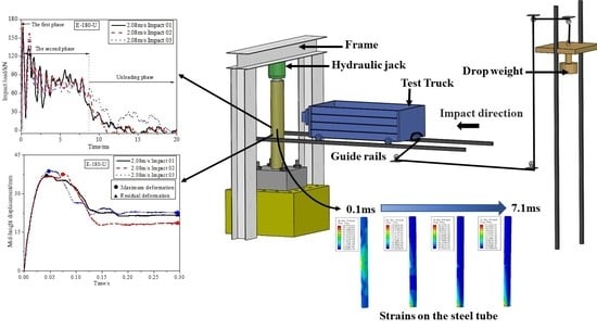
2.2. The Horizontal-Impact-Testing System

The horizontal-impact-testing system, as shown in Figure 2, is adopted to reproduce the collision onto the vertical columns or piers. It is comprised of a test truck, an axial pre-loading frame, guide rails, and a drop-weight system. The frame, which can sustain an axial load of 400 kN, is firmly fixed to the stable ground via high-strength bolts. The hydraulic jack can apply the axial load while simultaneously allowing it to move freely through a combination of the rollers stacked to the frame. The test truck consists of an instrumented hammer at the head which is designed to be stiff. Four specially designed steel hollow cylinders are designed to connect the hammer and the truck. The truck moving on the horizontal guide rails can be propelled towards the test specimens by the drop weight. Additional steel plates can be inserted to increase the weight of the impact truck that has an initial value of 1200 kg, and can be increased to the maximum value of 3000 kg. The impact velocity can be changed with the location of the drop weight with varying heights in the range of 0 to 18 m.
The test truck is propelled by the drop-weight system. The drop weight can move on the slipway in the vertical direction. The steel wire connects the test truck and the drop weight. One end of the steel wire is fixed to the drop weight, and the other end features a loop to fit the separation with the test truck when the stopper location is reached. At the stopper location, the test truck is close to the specimen with a space of about 150 mm. Thus, the impact collision can be applied after the drop weight is released and the constant velocity can be achieved.

2.3. Data Measuring Instrumentation

To measure the impact velocity of the test truck, a laser velocity sensor was employed at the stopper location. The impact force was measured by the strain gauges on the four steel hollow cylinders connected to the truck and the instrumented hammer, which proved to be effective [26]. Four linear variable displacement transducers (LVDTs) were installed at the bottom, h/4, h/2, and the top of the column to monitor the movements during the tests. Here, h is the height of the column. The load at the top of the column was measured by the transducers inside the hydraulic jack. Meanwhile, the axial load can be maintained during the test. The location distribution of the LVDTs is shown in Figure 3a. On the other hand, nine longitudinal strain gauges were attached to the steel tubes to measure the longitudinal strain distributions of the columns at three cross-sections (A to C from the column bottom end). The layout of the strain gauges is shown in Figure 3b.

2.4. Test Setup

The horizontal-impact-testing system was utilized in the current test. All the specimens described above were tested under a constant axial load and impact loads. The elliptical CFT columns should be aligned for the installation at the tested location. The target velocities were calibrated by a tested column before the test to determine the height of the drop weight. The axial load was applied first and remained constant after reaching a certain level. Then the drop weight was positioned at the determined height. Meanwhile, the test truck was pulled to a certain distance from the specimen to ensure the steel wire was under tension. Once the drop weight was suddenly released, the test truck accelerated until the stopper position aimed towards the vertical impact position on the specimen. The test-truck collision on the specimen occurred. The impact velocity was detected using a laser velocity senor, which triggered all the sensors. The test was terminated until the axial load could not be maintained.

3. Experimental Results and Discussion

3.1. Test Observations

All the tested specimens showed the global deformations under the impact loading, no matter the differences of the cross-section geometries or the impact velocities. No noticeable outward buckling on the steel tubes was found during the test. This illustrates that the elliptical CFT columns have excellent impact performance. The deformation of the columns increased with progressively increasing impact velocities. Meanwhile, the specimens experienced the increased lateral deformations with the increasing impact numbers under the same impact velocity. Figure 4 shows the deformed columns at the final failure under the last impact.

3.2. Impact Load-Time History

The impact load is an essential factor in studying the impact-resistance capability of an elliptical CFT column. To better understand the impact load, the measured impact load-time histories for all the specimens are displayed in Figure 5. Herein, the impact 01 represents the first impact, impact 02 represents the second impact, and so on.
The shapes of the impact load-time histories recorded for all the specimens are similar. As depicted in Figure 5, impact load-time histories can be divided into three phases for all the specimens, including the sharp first peak-force phase, the vibration and plateau phase, the unloading phase, and the rebounded second impact.
In the first phase, it is evident that the impact force increased sharply to the initial peak force within about 0.2 ms as the specimen was accelerated by the test truck. It can be found that the specimens under the same impact velocity had almost the same stiffness; however, the stiffness quickly increased with the increasing impact velocity. Meanwhile, the first impact force was mainly governed by the impact velocity, and the first peak impact force exhibited a significant increase with high-impact velocity. A peak value of 137.53 kN was measured on the column E-120-I at the impact velocity of 2.31 m/s, while higher peak loads of 166.9 kN, 198.4 kN, and 209.9 kN were obtained at the velocities of 2.71 m/s, 3.12 m/s, and 3.42 m/s, respectively. Column E-180-I had approximately the same reaction; however, specimen E-180-I had a higher peak value than that of E-120-I. This is due to the more significant impact sectional modulus of specimen E-180-I, along the major axis. For the specimen C-180-I, the peak value would reach to 407.3 kN at the impact velocity of 3.88 m/s, while the peak value of 209.5 kN was obtained at the impact velocity of 1.80 m/s.
Under the same impact velocity, the peak impact load increased and then decreased due to the increased impact occurrences. Additionally, the curves are almost the same during the first phase of the specimens. For specimen E-180-U, the peak load for the impact 01 was 168.1 kN. A higher peak load of 174.9 kN was obtained for the impact of 02 for the confinement of the steel tube, while a lower peak load of 161.7 kN for the impact of 03 had resulted in the damage of the concrete and steel tube. The same phenomenon was observed for specimen E-120-U. The peak load values for the impact 01, impact 03, and impact 05 were 93.7 kN, 103.2 kN, and 91.1 kN, respectively, for the specimen E-120-U.
In the second phase, there was a gap between the first and second peak forces, implying that the specimen had a higher velocity than the test truck after the impact. Then a second peak force was obtained as the specimen and the test truck acquired a common velocity. Comparing with the first peak force, the second peak force was lower, except with specimen E-120-U. This seems to imply that the specimen had damage after the first impact force. Then, the impact force dropped and vibrated with an individual value. It can be observed that E-180-I had lower individual values than E-120-I. Similar results can be observed for the specimens E-120-U and E-180-U. It can be concluded that the increase in the stiffness induced by the cross-section leads to a moderate increase in the plateau value.
Finally, the impact force comes to the unloading phase. The test truck and the specimen being separated from each other caused the impact force to reduce to zero; however, the rebounded specimens may have a higher velocity than the test truck, so the second impact occurred. This phenomenon can be observed at a high-impact velocity. Additionally, the loading duration for the second impact became slightly longer with the increased velocity. Compared with the first impact, the peak impact force of the second impact was lower. For specimen E-120-I, at the impact velocity of 2.31 m/s, the second impact force increased up to 40.3 kN.
Figure 6 shows the effect of the impact velocity on the peak impact force. It can be found that the peak impact load increased with the increased impact velocities. This can be explained by the fact that higher peak impact load was obtained due to higher moment capacity of the specimen in the impact direction. As observed from Figure 6, the peak impact loads had negligible changes for the specimen under the same impact velocity. Specimen E-120-I exhibited a lower peak impact load than the other specimens, due to the fact that specimen E-120-I had a smaller impact sectional modulus along the minor axis.

3.3. Displacement Time Histories

For all the tested specimens, the displacement time histories at the mid-height and top points of the column are presented in Figure 7 and Figure 8, respectively. Meanwhile, the maximum deformation and residual deformation at the mid-height are given in Table 2. It can be found that the elliptical CFT columns have better ductilities under impact loads with higher displacements. The shapes of displacements at the top of the column are similar to those at the mid-height. The displacement at the top of the column was almost two times the mid-height displacement, but with a delay. This delay may be caused by the time required for the stress waves to travel from the impact point towards the top of the column. As shown in Figure 7 and Figure 8, the maximum displacement of the column increased significantly with the impact velocities increasing from 1.88 m/s to 3.88 m/s; however, the same impact velocity did not change the column’s displacement, which demonstrated that the column was still in the elastic stage, especially for column E-180-U. The free-vibration period, approximately 40 ms, was obtained for column E-180-U. At the same impact velocity of about 2.3 m/s, the maximum displacement at the impact point of column E-120-I was 34 mm, while the corresponding values for columns E-180-I and C-180-I were 113 mm and 23 mm, respectively.

3.4. Strain and Strain Rates

The typical load-longitudinal strain curves of the elliptical steel tubes are illustrated in Figure 9. It can be seen that the stain curves showed similar trends when reaching the maximum values, followed by the descending branches in half-sine waveform. The strain gauge 3(A) positioned on the bottom face in the tension region of specimen E-120-I showed the maximum values, which were approximately double the values of the strain gauge 6(B). At the first three impacts, the elastic strain on the steel tube was obtained until impact 04. It can also be noticed from Figure 9b that the strains developed quickly at impact 04 and impact 05, as the steel tube entered the plastic state.
Compared to the static load, the strain rate is considered under impact load. The compressive strain-rate curves are showed in Figure 9c and were calculated using the compressive strain–time relationships. The maximum strain rates were calculated, varying from −0.11 to −0.21 s−1 under different impacts onto the compression region of specimen E-120-U. Thus, the strain rates in this test were small as the impact velocities were low.

3.5. Energy Absorption

The energy absorption, which can be estimated by the enclosed area under the impact mid-height load-displacement curve (as shown in Figure 10), is another critical factor to evaluate the impact resistances of the columns, shown in Table 2. The impact impulse, derived from the enclosed area of the impact force time history, is also presented in Table 2. The elliptical CFT columns with the increased impact velocity exhibited an improvement in energy absorption. At the same impact velocity, the columns dissipated almost the same energy. It also indicated that the damage to the elliptical CFT columns was rarely small. As shown in Figure 11, more energy was dissipated with the applied impulses. The second and third impact energy absorptions for column E-120-I were 44.3% and 88.2% higher than that of the first impact, respectively. Under the same impact velocity of 2.3 m/s, the corresponding impact energy absorptions of columns C-180-I and E-180-I were 3044.1 J and 5528.3 J, respectively. Additionally, the residual displacements were 6.05 mm and 29.92 mm, respectively. Therefore, it can be concluded that the CFT column C-180-I had lower damage under lateral impacts. For E-120-U, the dissipated energy was almost 1200 J, with an impulse of about 2125 kN·ms. This indicates that the specimen still had the capacity to resist more dissipated energy after the five relatively low-velocity impacts, even after the noticeable residual displacement increased. The CFT column E-180-U had very similar dissipated energy with the column E-120-U.

4. Finite Element Modeling

4.1. Finite Element Model

To simulate the dynamic responses of elliptical CFT columns under lateral impact loading, a detailed finite element analysis model was developed using ABAQUS/Explicit software. The stress–strain relation of the steel tube was assumed to be linearly-elastic and perfectly-plastic, satisfying von Mises’ plasticity theory. The damaged plasticity model of concrete (CDP) provided by the software model library was used to describe the behavior of the core concrete. The effect of the strain-rate on concrete was considered [17].
In the model, the steel tube and core concrete were simulated by eight-node reduced-integration three-dimensional brick elements (C3D8R), respectively; moreover, the test truck was simplified to be a rigid block with the same weight as the same impacted surface. The hard contact behavior in the normal direction of the concrete-steel tube surfaces was assumed with no penetration allowed and the tangent contact was simulated through the Coulomb friction model with a friction coefficient of 0.6. The steel tube and core concrete were tied together with the foundation, which was fixed with all degrees of freedom restricted. The axial load was applied at first; then, the test velocity was defined for the rigid block to apply the lateral impact loading.

4.2. Verifications of the FEA Model

The FEA model was verified by the experimental results. No local buckling was observed from the FEA model, which was similar with the experiment ones. Figure 12 and Figure 13 present the comparisons of impact load-time histories and impact displacement-time histories between the tested results and the predicted ones of the specimens E-180-I and E-180-U, respectively. It can be found that a generally good agreement was obtained for the second phase of the impact load-time history and the impact displacement-time history between both results. The difference may be that the axial load cannot slide freely in the test, or signal interference and material variability in the experiment were differences between the measured results and the predicted results [29]. Thus, the FEA model can be used to predict the elliptical CFT columns under lateral loading.

4.3. Strain Mechanism Analysis

Figure 14 and Figure 15 demonstrate the strains of the steel tube and core concrete of specimen E-180-U at the impact velocity of 2.08 m/s in the first impact. It can be found that the strain generally went through four stress states:
(1)
Local response: In this state, when the test truck made contact with the specimen, the stress rapidly increased at the impact location. Also, slight damage of steel tube and core concrete was obtained at the impact location. The stress wave, produced by the impact, spread to the two ends of the column. At the same time, the impact force rapidly increased from zero to the peak value and the deformation was almost zero. This shows that the impact force was basically balanced by the inertial force. At the same location, the strain on the concrete was larger than that on the steel tube. This indicates that the slip occurred between the steel tube and the concrete. Thus, the deformation coordination condition was not satisfied;
(2)
Overall response: After the peak load, the specimen showed its overall response. The strain gradually increased at the bottom of the column. In this stage, the stress wave travelled through the whole specimen. The strain of the specimen dramatically increased; meanwhile, the damage extended at the impact location;
(3)
Stable response: In this stage, the impact force generally remained stable; however, the kinetic energy of test truck was converted into internal energy of the specimen, and the deformation increased. Thus, the strains of steel tube and core concrete developed further. The plastic region at the bottom of specimen continued to expand;
(4)
Descending response: In this stage, the impact force decreased to zero. This indicates that the test truck separated with the specimen and they reversed their velocity direction. Then, the specimen reached the maximum displacement. At last, the deflection of the specimen stayed at the residual deformation with the vibration. The plastic region of the concrete was larger than that of the steel tube.

5. Conclusions

This paper has presented the investigation on the dynamic behavior of the elliptical CFT columns subjected to lateral impact loading. From the test results, the test observations, impact load-time histories, displacement time histories, energy dissipation and finite element model for the specimens were explored. The main conclusions can be drawn as follows:
(1)
Under the lateral impact load, the elliptical CFT columns had good impact performance. The columns had global deformations with noticeable outward buckling of the steel tubes;
(2)
The impact load-time histories can be divided into three phases. The first impact force was mainly governed by the impact velocity within about 0.2 ms. Under the same impact velocity, the first peak impact load increased and then decreased due to the increased times of impact. A second peak force was obtained at the same velocity acquired by the specimen and test truck. The test truck and the specimen separated following the unloading phase;
(3)
The elliptical CFT columns have good ductility under an impact load with higher displacements. The displacement at the column top was almost twice the value at the mid-height but with a delay;
(4)
The strains and strain rates descended in half-sine waveforms after reaching the maximum values. The strain rates in this study were small as the impact velocities were small. The elliptical CFT columns dissipated almost the same energy under the same impact velocity, and more energy was dissipated with the increased impact velocity;
(5)
The dynamic responses of elliptical CFT columns under lateral impact loading can be simulated by establishing the finite element model. The mechanical mechanism of the strains can be divided into four stages. The stress wave travelled through the whole specimen at the overall response, while the strain was obtained at the impact location during the local response. The strains developed more extensively during the stable responses. Also, the vibrations of the specimens occurred during the descending responses.

Author Contributions

Conceptualization, Y.W.; methodology, Y.W. and S.H.; software, Y.W. and S.H; validation, Y.W.; formal analysis, Y.W.; investigation, Y.W.; resources, Y.W.; data curation, S.H.; writing—original draft preparation, Y.W.; writing—review and editing, Y.W.; visualization, Y.W. All authors have read and agreed to the published version of the manuscript.

Funding

This research was funded by the PhD Start-up Foundation of Foshan University (GG040931) and the Fund for Science and Technology Innovation of Foshan (2020001005479). Their support for the research is acknowledged with thanks.

Institutional Review Board Statement

Not applicable.

Informed Consent Statement

Not applicable.

Data Availability Statement

Not applicable.

Conflicts of Interest

The authors declare no conflict of interest.

References

  1. Deng, L.; Wang, W.; Yu, Y. State-of-the-art review on the causes and mechanisms of bridge collapse. J. Perform. Constr. Facil. 2016, 30, 4015005. [Google Scholar] [CrossRef]
  2. El-Tawil, S.; Severino, E.; Fonseca, P. Vehicle collision with bridge piers. J. Bridge Eng. 2005, 10, 345–353. [Google Scholar] [CrossRef] [Green Version]
  3. Espinos, A.; Romero, M.L.; Serra, E.; Hospitaler, A. Circular and square slender concrete-filled tubular columns under large eccentricities and fire. J. Constr. Steel Res. 2015, 110, 90–100. [Google Scholar] [CrossRef]
  4. Han, L.H.; Li, W.; Bjorhovde, R. Developments and advanced applications of concrete-filled steel tubular (CFST) structures: Members. J. Constr. Steel Res. 2014, 100, 211–228. [Google Scholar] [CrossRef]
  5. Uy, B. Stability and ductility of high performance steel sections with concrete infill. J. Constr. Steel Res. 2008, 64, 748–754. [Google Scholar] [CrossRef]
  6. Naghipour, M.; Yousofizinsaz, G.; Shariati, M. Experimental study on axial compressive behavior of welded built-up CFT stub columns made by cold-formed sections with different welding lines. Steel Compos. Struct. 2020, 34, 347–359. [Google Scholar]
  7. Liao, J.J.; Zeng, J.J.; Long, Y.L.; Cai, J.; Yi, O.Y. Behavior of square and rectangular concrete-filled steel tube (CFST) columns with horizontal reinforcing bars under eccentric compression. Eng. Struct. 2022, 271, 114899. [Google Scholar] [CrossRef]
  8. Zhao, X.L.; Packer, J.A. Tests and design of concrete-filled elliptical hollow section stub columns. Thin-Walled Struct. 2009, 47, 617–628. [Google Scholar] [CrossRef]
  9. Yang, H.; Lam, D.; Gardner, L. Testing and analysis of concrete-filled elliptical hollow sections. Eng. Struct. 2008, 30, 3771–3781. [Google Scholar] [CrossRef]
  10. Mahgub, M.; Ashour, A.; Lam, D.; Dai, X. Tests of self-compacting concrete filled elliptical steel tube columns. Thin-Walled Struct. 2017, 110, 27–34. [Google Scholar] [CrossRef] [Green Version]
  11. Cai, Y.; Quach, W.; Young, B. Experimental and numerical investigation of concrete-filled hot-finished and cold-formed steel elliptical tubular stub columns. Thin-Walled Struct. 2019, 145, 106437. [Google Scholar] [CrossRef]
  12. Ipek, S.; Erdoğan, A.; Güneyisi, E.M. Compressive behavior of concrete-filled double skin steel tubular short columns with the elliptical hollow section. J. Build. Eng. 2021, 38, 102200. [Google Scholar] [CrossRef]
  13. Long, Y.L.; Zeng, L. A refined model for local buckling of rectangular CFST columns with binding bars. Thin-Walled Struct. 2018, 132, 431–441. [Google Scholar] [CrossRef]
  14. Long, Y.L.; Zeng, L.; Gardner, L.; Wadee, M.A. A new model for calculating the elastic local buckling stress of steel plates in square CFST columns. Thin-Walled Struct. 2022, 171, 108756. [Google Scholar] [CrossRef]
  15. Banthia, N.; Mindess, S.; Bentur, A.; Pigeon, M. Impact testing of concrete using a drop-weight impact machine. Exp. Mech. 1989, 29, 63–69. [Google Scholar] [CrossRef]
  16. Remennikov, A.M.; Kong, S.Y.; Uy, B. Response of foam- and concrete-filled square steel tubes under low-velocity impact loading. J. Perform. Constr. Facil. 2011, 25, 373–381. [Google Scholar] [CrossRef]
  17. Wang, R.; Han, L.H.; Hou, C.C. Behavior of concrete filled steel tubular (CFST) members under lateral impact: Experiment and FEA model. J. Constr. Steel Res. 2013, 80, 188–201. [Google Scholar] [CrossRef]
  18. Yousuf, M.; Uy, B.; Tao, Z.; Remennikov, A.; Liew, J.Y.B. Impact behaviour of pre-compressed hollow and concrete filled mild and stainless steel columns. J. Constr. Steel Res. 2014, 96, 54–68. [Google Scholar] [CrossRef]
  19. Yang, Y.; Zhang, Z.; Fu, F. Experimental and numerical study on square RACFST members under lateral impact loading. J. Constr. Steel Res. 2015, 111, 43–56. [Google Scholar] [CrossRef] [Green Version]
  20. Chen, L.; Wu, H.; Fang, Q.; Li, R.W. Full-scale experimental study of a reinforced concrete bridge pier under truck collision. J. Bridge Eng. 2021, 26, 05021008. [Google Scholar] [CrossRef]
  21. Aghdamy, S.; Thambiratnam, D.P.; Dhanasekar, M. Experimental investigation on lateral impact response of concrete-filled double-skin tube columns using horizontal-impact-testing system. Exp. Mech. 2016, 56, 1133–1153. [Google Scholar] [CrossRef]
  22. Sha, Y.; Hao, H. Laboratory tests and numerical simulations of barge impact on circular reinforced concrete piers. Eng. Struct. 2013, 46, 593–605. [Google Scholar] [CrossRef]
  23. Zhang, X.H.; Hao, H.; Li, C. Experimental investigation of the response of precast segmental columns subjected to impact loading. Int. J. Impact Eng. 2016, 95, 105–124. [Google Scholar] [CrossRef] [Green Version]
  24. Feng, Z.J.; Wang, X.l.; Zhang, S.F.; Chu, Y.P. Experimental investigation on cantilever square CFST columns under lateral continuous impact loads. J. Constr. Steel Res. 2022, 196, 107416. [Google Scholar] [CrossRef]
  25. Demartino, C.; Wu, J.G.; Xiao, Y. Response of shear-deficient reinforced circular RC columns under lateral impact loading. Int. J. Impact Eng. 2017, 109, 196–213. [Google Scholar] [CrossRef]
  26. Ye, J.B.; Wang, Y.T.; Cai, J.; Chen, Q.J.; He, A. Evaluation of residual lateral capacities of impact-damaged reinforced concrete members. Buildings 2022, 12, 669. [Google Scholar] [CrossRef]
  27. Batarlar, B.; Hering, M.; Bracklow, F.; Kühn, T.; Beckmann, B.; Curbach, M. Experimental investigation on reinforced concrete slabs strengthened with carbon textiles under repeated impact loads. Struct. Concr. 2021, 22, 120–131. [Google Scholar] [CrossRef]
  28. Abdallah, M.H.; Hajiloo, H.; Braimah, A. Structural response of circular concrete columns confined with gfrp tubes under repeated and sequential impact loads. SSRN 2022, 7, 4159300. [Google Scholar] [CrossRef]
  29. Kadhim, M.M.A.; Semendary, A.A.; Hammed, M.; Cunningham, L.S. Numerical investigation of hybrid UHPC columns subject to lateral impact. J. Bridge Eng. 2022, 47, 103914. [Google Scholar] [CrossRef]
Figure 1. Cross-sections of two typical specimens. (a) Circular; (b) Elliptical.
Buildings 12 01847 g001
Figure 2. Impact test setup. (a) Sketch of the facility; (b) The instrumented hammer with test truck; (c) Test truck on the rails; (d) Specimen inside the frame; (e) Drop weight.
Buildings 12 01847 g002
Figure 3. Location distributions of (a) LVDTs and (b) Strain gauges.
Buildings 12 01847 g003
Figure 4. Global failure patterns of the specimens. (a) E-120-I; (b) E-120-U; (c) E-180-I; (d) E-180-U; (e) C-180-I.
Buildings 12 01847 g004
Figure 5. Impact load-time histories for all the specimens. (a) E-120-I; (b) E-120-U; (c) E-180-I; (d) E-180-U; (e) C-180-I.
Buildings 12 01847 g005aBuildings 12 01847 g005b
Figure 6. Effect of the impact velocity on the peak impact force.
Buildings 12 01847 g006
Figure 7. Mid-height displacement time histories of the columns. (a) E-120-I; (b) E-120-U; (c) E-180-I; (d) E-180-U; (e) C-180-I.
Buildings 12 01847 g007
Figure 8. Column top displacement time histories. (a) E-120-I; (b) E-120-U; (c) E-180-I; (d) E-180-U; (e) C-180-I.
Buildings 12 01847 g008
Figure 9. Typical strain and strain rates of the steel tube. (a) Strain curves in the tension region of the specimen E-120-I. (b) Strain curves in the compression region of the specimen E-120-U. (c) Strain rates of in the compression region of the specimen E-120-U.
Buildings 12 01847 g009aBuildings 12 01847 g009b
Figure 10. Calculation of the energy absorption.
Buildings 12 01847 g010
Figure 11. Energy dissipation vs. impulses relationships for all the tested specimens.
Buildings 12 01847 g011
Figure 12. Impact load-time histories for the specimens (a) E-180-I and (b) E-180-U.
Buildings 12 01847 g012
Figure 13. Impact displacement time histories for the specimens (a) E-180-I and (b) E-180-U.
Buildings 12 01847 g013
Figure 14. Strains on the steel tube. (a) Local response, 0.1 ms; (b) Overall response, 1.3 ms; (c) Stable response, 5.3 ms; (d) Descending response, 7.1 ms.
Buildings 12 01847 g014
Figure 15. Strains on the core concrete. (a) Local response, 0.1 ms; (b) Overall response, 1.3 ms; (c) Stable response, 5.3 ms; (d) Descending response, 7.1 ms.
Buildings 12 01847 g015
Table 1. Parameters of the tested specimens.
SpecimensD/B/t/L
mm
fc/
mPa
fy/
mPa
fu/
mPa
N/
kN
Impact
Direction
E-120-I180/120/6/220029.62331.6480.9184along the minor axis
E-120-U180/120/6/220029.62331.6480.9184along the minor axis
E-180-I180/120/6/220029.62331.6480.9184along the major axis
E-180-U180/120/6/220029.62331.6480.9184along the major axis
C-180-I180/180/6/220029.62331.6480.9251along the major axis
Denotation: fy is the yield strength of the steel tube; fu is the ultimate strength of the steel tube; N is the applied axial load.
Table 2. Summary of the key results of the experimental CFT columns.
SpecimensImpact Velocity
m/s
PIF
/kN
Time
/ms
It/
kN·ms
Maximum Deformation
/mm
Residual Deformation
/mm
Energy Dissipation
/J
E-120-I2.31141.26.5 437 34.0816.592131
2.71166.97.1 488 41.4218.603075
3.12198.47.3 531 48.9423.744011
E-120-U1.20103.312.2 419 19.644.991035
1.20107.412.1 449 22.016.731223
1.20104.012.6 421 22.039.231222
1.20104.713.5 423 21.789.341239
1.20101.510.6 412 21.6010.021223
E-180-I1.31137.59.3 649 22.4415.271795
1.77175.510.5 748 39.7322.913282
2.04226.011.6 869 46.8826.004536
2.34240.416.3 1212 54.2829.925528
E-180-U2.08168.113.1 752 36.9822.463120
2.08174.910.9 755 37.5719.193192
2.08161.711.8 774 38.8422.633082
C-180-I1.8209.59.3 875 17.490.321878
2.36272.59.3 965 23.586.053044
2.8339.89.9 1058 30.5118.614754
3.19357.88.3 1008 39.9026.736273
3.5373.89.3 1082 48.5423.687597
3.88407.315.3 1464 55.5728.729198
Denotation: PIF (peak impact force); It (impulses).
Publisher’s Note: MDPI stays neutral with regard to jurisdictional claims in published maps and institutional affiliations.

