Article

Aftershock Fragility Assessment of Continuous RC Girder Bridges Using a Modified Damage Index

1
State Key Laboratory of Disaster Reduction in Civil Engineering, Tongji University, 1239 Siping Road, Shanghai 200092, China
2
Tongji Architectural Design (Group) Co., Ltd., Shanghai 200092, China
*
Author to whom correspondence should be addressed.
Buildings 2022, 12(10), 1675; https://doi.org/10.3390/buildings12101675
Submission received: 19 August 2022 / Revised: 6 October 2022 / Accepted: 8 October 2022 / Published: 12 October 2022
(This article belongs to the Special Issue Improvement Technology on Building Seismic Toughness)

Abstract

:
Aftershock fragility is usually calculated conditioned on a range of potential post-mainshock damage states. The post-mainshock damage can be identified using damage indices, the latter being frequently associated with displacement-based parameters such as the maximum drift ratio or the residual displacement. However, when the reliable simulation of a structural system in a specific post-mainshock damage state is the objective of a numerical study, using such damage indicators may not assure the structure experiencing a homogeneous level of damage due to different mainshocks characteristics, which induce the aftershock fragility results unreliable. Along these lines, the current study presents a damage evaluation methodology mainly used for aftershock fragility assessment. It aims to reduce the variation of damage levels derived by using different mainshock seismic motions. The methodology presented herein includes: (i) the introduction of a damage index defined by comparing the monotonic pushover curve of the intact and post-earthquake damaged structure; (ii) the description of a finite element (FE)-based scheme that enables to quantify of the proposed damage index; and (iii) a deterioration-related modeling technique that can capture both strength and stiffness degrading performance of structural systems exposed to earthquake-induced excitations. The latter is essential to support the FE-based quantification scheme for the damage index. This methodology evaluation methodology can be primarily used for calculating the aftershock fragility assessment for a multi-span RC continuous girder bridge. The back-to-back incremental dynamic analysis framework uses a larger number of mainshock-aftershock artificial sequences to generate the aftershock fragility curves. The AS fragility results obtained via MBDI are compared with that via maximum drift ratio in terms of the ability to reduce the variation of residual capacities obtained using different mainshocks to induce a specific damage state but collapse by the same aftershock. The comparison shows a more robust relationship of MBDI with the residual capacity. It is found that MBDI, as well as its quantification approach proposed in this study, is a more effective damage predictor than the widely used displacement-based indices for AS fragility assessment.

1. Introduction

During major earthquake events, it is common to observe strong aftershocks within a short time window after the mainshock [1,2,3]. For example, the 2011 Tohuku earthquake (Japan) of moment magnitude Mw equal to 9 was followed by numerous aftershocks of Mw higher than 5, while the shortest time interval between two successive events was no longer than a few days [4]. Such a short time window observed for the occurrence of successive aftershock events renders it nearly impossible to retrofit the damaged structures promptly. Hence, a mainshock-affected structure is usually associated with a higher vulnerability to additional structural failures when exposed to subsequent aftershock(s), even when the aftershock’s intensity is lower than the mainshock. For example, the mainshock of the Kocaeli earthquake (Turkey, 17.08.1999, Mw = 7.4) damaged various structural systems. However, many of those structures eventually collapsed by an aftershock of lower magnitude (Mw = 5.9) that occurred almost a month after the mainshock [5]. Therefore, from a public safety perspective, it is essential to reliably assess the increased vulnerability of a mainshock-damaged structure subjected to potential aftershock(s) and hence, support the relevant post-earthquake decision-making.
The aftershock (AS) fragility, defined as the probability of exceeding a particular damage state given the intensity of an aftershock and conditioned on a specific damage level induced by a mainshock, is a valuable tool to assess the seismic performance and quantify the vulnerability of structures to damages from earthquakes [6,7,8,9,10,11,12,13,14,15,16,17,18,19,20,21] and have been widely used for different types of structures, such as infilled RC structures [22], containment structures [23], and cast-in-place RC industrial structures [24]. Under successive ground motions, the structures may suffer from an increased number of hysteresis loops compared to a single ground motion event. Therefore, it is relevant for AS fragility to consider a damage index that captures the cumulative damage and the different deterioration mechanisms (e.g., stiffness and strength degradation) that govern the cyclic performance of structural systems subjected to seismic motions.
Most of the existing studies on AS fragility has adopted displacement-based damage indices, such as the maximum drift ratio or the residual displacement, due to their calculation-related simplicity (e.g., [10]). However, several studies have found that even if the maximum or residual displacement of a structure under different ground motions is identical, the degree of structural damage could be quite different [25,26]. Therefore, a relatively deficient representation of the structural damage can be seen by using those damage indices, and the latter can adversely affect the reliability of AS fragility since the simulation of a specific post-mainshock damage state using such damage indices may fail to ensure a homogeneous damage level due to different mainshocks.
Along these lines, the Park and Ang (PA) damage index [27,28], widely used in the literature, evaluates seismic damage by linearly combining the large deformation induced by the earthquake excitation and the corresponding energy dissipation. This integrated (i.e., hybrid) damage index is comprehensively calibrated against a large amount of observed seismic damages, including shear and bond failures. However, several difficulties have arisen with using the proposed equation for the PA index. A critical problem is related to the weighting factor, which has to be assigned to the energy dissipation term and has to be assigned arbitrarily because the factor varies with structural configuration and section properties [29]. Furthermore, the linear relationship between the two terms of the PA damage index has been frequently found inappropriate for capturing structural damage efficiently [29].
An alternative, still hybrid, damage index was presented by Bracci et al. (the Bracci damage index, BDI) [30]. BDI is defined in terms of the loss ratio of the monotonic load-deformation curve area due to the extremal loading. The loss area of a load-deformation curve is caused by both the strength degradation and the irrecoverable deformations. Bracci et al. [30] suggested a quantification procedure for BDI, in which the simplified bilinear moment-curvature relationship is employed to represent the actual physical property of the structure, and the yield curvature, being necessary for the BDI calculation, is modified after each cycle accounting for both the plastic deformation and the stiffness degradation. The formulation of the BDI in terms of the moment-curvature relationship renders this damage index sufficiently correlated with the seismic performance [29]; hence, it can favor the reliable simulation of post-mainshock damage, which is of primary interest for the AS fragility. However, some application-related restrictions are caused by the proposed quantification procedure for the BDI. First, the BDI analytical expression includes a weighting factor related to the degrading bilinear moment–curvature curve and is defined arbitrarily [29]. The latter undermines the reliability of the estimated damage that is also disfavored by the relatively simple bilinear moment-curvature curve currently used [31]. Most importantly, since the quantification procedure has to modify the moment-curvature curve after each cycle, the BDI is associated with a demanding calculation that restricts its application in engineering practice.
In order to solve the problems mentioned above, the central objective of the current study is the development of a damage evaluation framework oriented to favor the AS fragility assessment and lead, eventually, to fragility results of increased reliability compared to existing schemes. The integrated and novel methodology presented herein consists of (i) an advanced damage index, (ii) a finite element (FE)-based quantification procedure for this damage index, and (iii) a deterioration modeling technique that supports the quantification procedure. Significantly, the damage index is developed after the appropriate modification of the existing BDI and accounts not only for the peak and residual displacement but also for the stiffness and strength deterioration, the latter being relevant for the seismic response of structures. The proposed quantification procedure of the modified BDI damage index is based on FE analysis with the use of a deterioration modeling technique that effectively captures strength and stiffness degrading performance. The proposed damage evaluation framework is applied herein for the AS fragility assessment of a multi-span reinforced concrete (RC) continuous girder bridge. At the same time, a large number of mainshock-aftershock artificial sequences are used within the B2B-IDA (back-to-back incremental dynamic analysis) scheme to generate AS fragility curves. The performance of the current damage evaluation procedure is comparatively assessed with existing damage indices regarding the variation of collapse capacity of the damaged structures induced by different mainshocks. The major contribution of the proposed methodology is the refinement of an effective predictor for evaluating cumulative damage for AS fragility assessment, which can provide powerful support for the performance-based earthquake design of infrastructures considering aftershocks.

2. Modified Bracci Damage Index and FE-Based Quantification

This section presents the modified BDI damage index, currently proposed for the AS fragility assessment of structures subjected to earthquake hazards. The necessary quantification procedure of the modified BDI is also described herein based on FE model analysis.

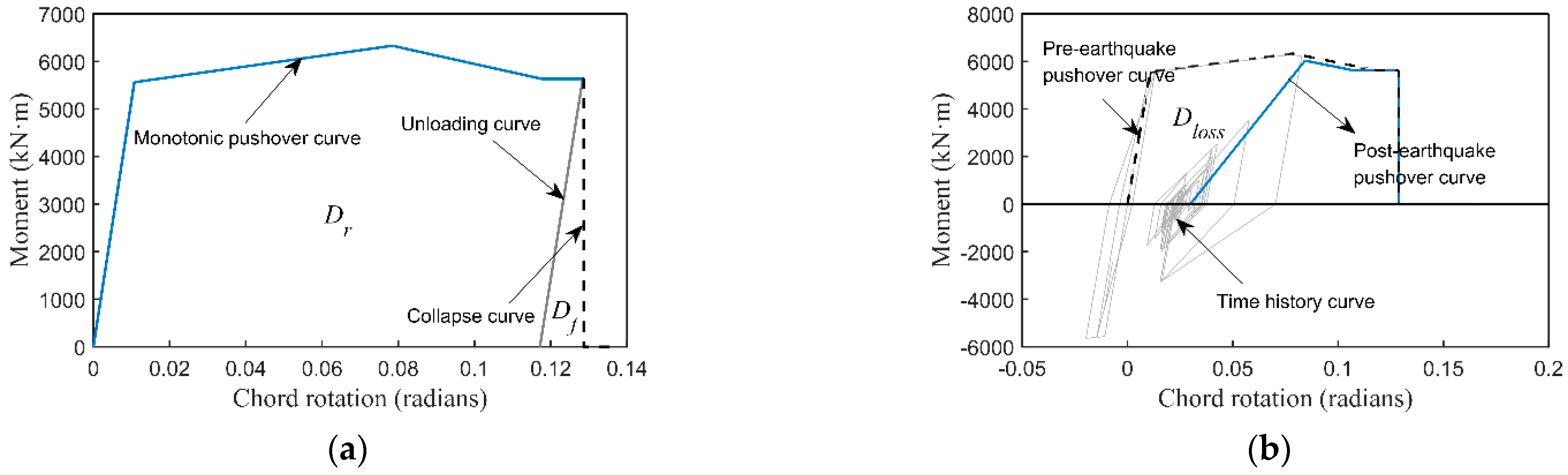
2.1. Definition of the Modified Bracci Damage Index

Identical to the original definition of the BDI, the modified one herein (MBDI) employs the philosophy of assessing the seismic-induced structural damage in terms of the loss ratio of the monotonic load-deformation curve area compared to the one corresponding to the intact structure. Especially in the MBDI model, Dr, as shown in Figure 1, is defined as the total area under the post-earthquake reloading pushover curve. This area initiates from the residual displacement point and, via the reloading curve, merges into the degraded post-earthquake monotonic curve. Df is defined as the area under the unloading curve that starts from the ultimate point of the intact monotonic backbone curve and ends by the zero-force point. Finally, D0 is the total area under the intact monotonic load-deformation curve of the structure under investigation.
Based on the above, the area loss of the monotonic load-deformation curve during the earthquake can be calculated as follows:
D l o s s = D 0 D r
Furthermore, the maximum loss of area is:
D p = D 0 D f
Hence, MBDI can be calculated as follows:
M B D I = D l o s s D p

2.2. FE-Based Quantification of MBDI

Following the MBDI definition, the main challenge for its rigorous quantification is determining the post-earthquake monotonic reloading pushover curve of the structure under study. To this end, an FE-based quantification procedure consists of five steps, as illustrated in Figure 2.
Step 1—Development of deterioration numerical model: The structure under study needs to be numerically simulated with an appropriate deterioration constitutive model that can capture the structural degrading performance of structural elements accounting for the earthquake-induced cumulative damage, such as the strength deterioration in the backbone curve as well as the cyclic deterioration of strength and stiffness under seismic loading. The deterioration model constitutes a crucial part of the MDBI quantification procedure; hence, mode details are provided in the following section.
Step 2—Monotonic pushover analysis of the intact structure: A monotonic pushover analysis needs to be performed by using the finite element model of the intact structure. This inelastic static analysis should lead the structure to respond just before its final performance phase, in which the collapse mechanism can be triggered (see the blue line in Figure 3a). By executing this step, both D0 and Df can be calculated. Eventually, the maximum possible area loss, Dp, can be estimated according to Equation (2).
Step 3—Structural analysis under the target load: The finite element model of the structure under study will be used for its structural analysis when exposed to the target external loading. Either quasi-static or dynamic loads can be considered. At the same time, various outcomes from the structural analysis (e.g., the moment–rotation relationship presented by the dark gray line in Figure 3b) can be used to simulate the cyclic degradation behavior under the target load according to the cumulative deterioration model developed in Step 1.
Step 4—Monotonic pushover analysis of the damaged structure: The analysis of the structure under the target external loading should be followed by the performance of a back-to-back monotonic pushover analysis until the collapse in order to determine the residual pushover curve of the damaged structure (i.e., the blue line in Figure 3b). By doing so, Dr and Dloss can be determined according to Equation (1).
Step 5—Calculation of MBDI: The damage index proposed herein can be calculated according to Equation (3).

3. Deterioration Modeling Technique

The deterioration modeling is essential herein to support the FE-based quantification procedure for the MDBI. Along these lines, lumped plasticity (LP) models have been widely seen to provide quite reliable results compared with fiber element models performing, especially at lower levels of deformation that drive the losses. Additionally, both strength and stiffness degradation, usually occurring as the structure approaches collapse, have been sufficiently captured by LP models [32,33,34,35], the latter being challenged in real applications due to the rather cumbersome calculation of the essential backbone curve parameters. Therefore, the deterioration modeling technique proposed herein exploits the advantages of the lumped plasticity models while developing a straightforward method to determine the relevant backbone curve parameters. Next, the modeling technique is demonstrated via its application for bridge columns.

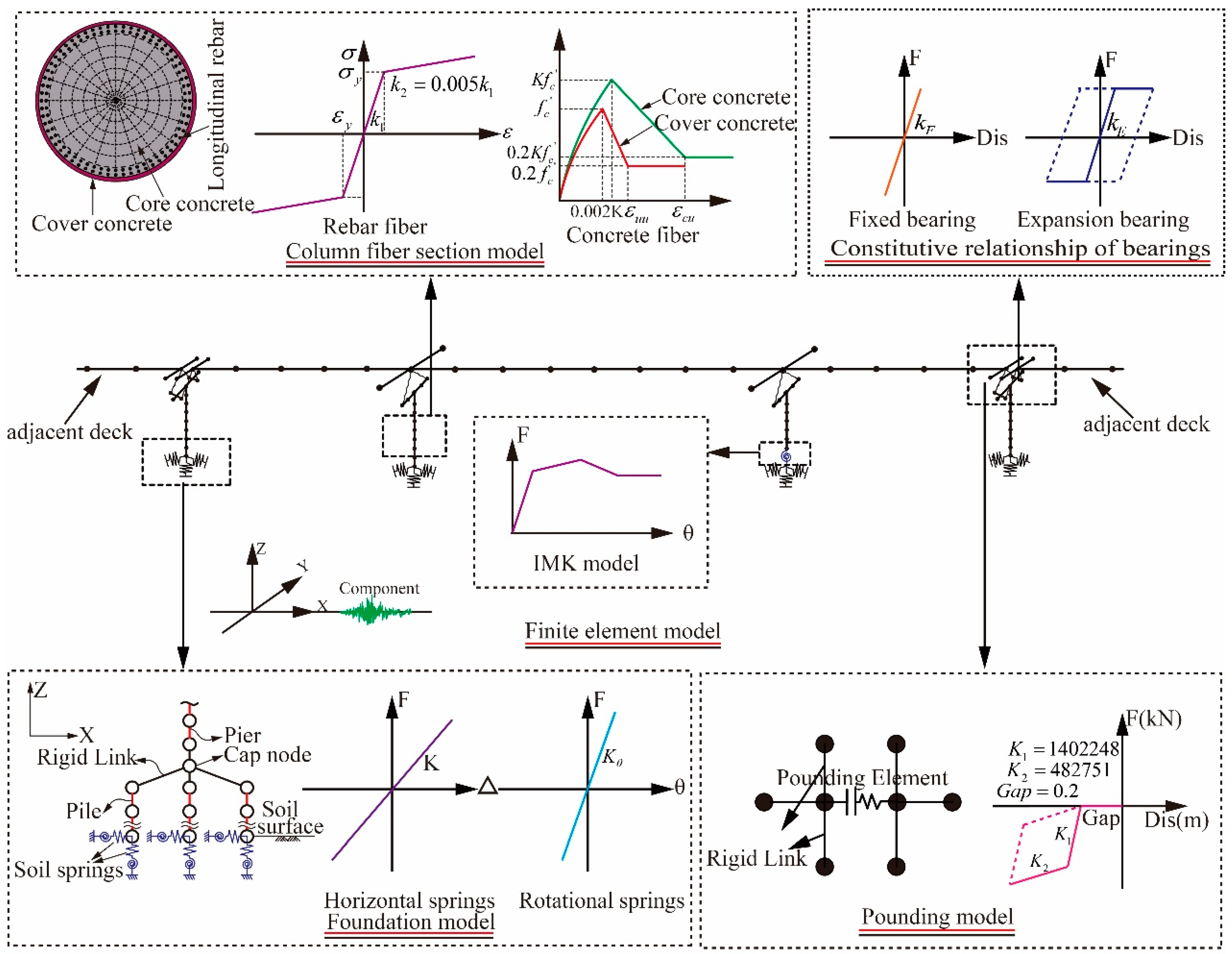
3.1. Lumped Plasticity Model of Bridge Columns

The modeling method described by the current study consists of three different types of elements, including a zero-length rotation spring for the bottom of the column and rigid and fiber-based elements (Figure 4c). Among them, the zero-length rotation spring and the rigid element are combined to act as the plastic hinge zone of the column. The length of the rigid element, as shown in Figure 4a, is estimated according to Equation (4), recommended by the Caltrans Seismic Design Criteria (Caltrans 2010), which considers the effects of strain localization and softening.
L p = 0.08 L + 0.22 f y e d b l 0.044 f y e d b l
where L is the column length, fye is the expected yield strength of longitudinal reinforcement, and dbl is the nominal bar diameter of longitudinal reinforcement.
The zero-length rotation spring employs the modified Ibarra–Medina–Krawinkler deterioration hysteretic model (IMK model) proposed by Lignos and Krawinkler [36,37]. This model is defined by a moment–rotation backbone curve and associated hysteretic rules. It can capture the strength and stiffness deterioration of RC columns up to the onset of structural collapse. The peak-orientated model is selected here as the associated hysteretic rules in this study.

3.2. Definition of Lumped Plasticity Model

The lumped plasticity model needs the definition of the backbone curve parameters and the cyclic deterioration parameters.

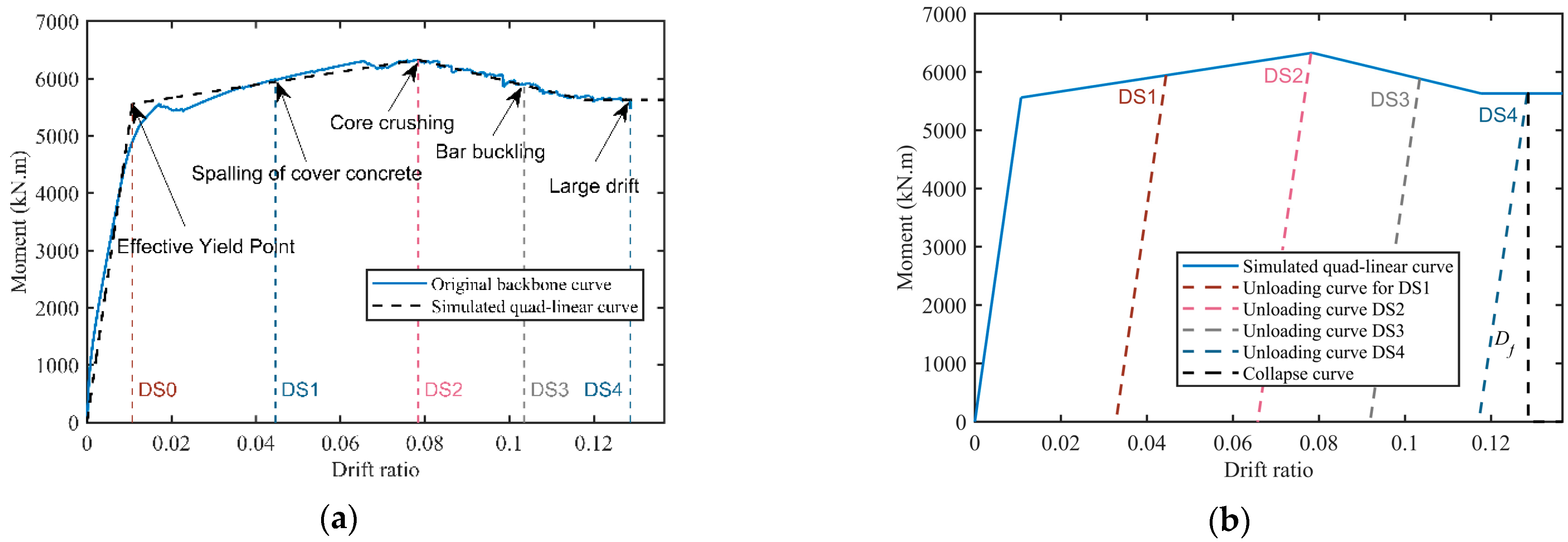
3.2.1. Definition of Backbone Curve Parameters

The parameters of the IMK model can be classified into two categories: the parameters that define a quad-linear backbone curve and energy-based cyclic deterioration parameters that define four cyclic strength and stiffness degradation modes. Even though Lignos and Krawinkler [36,37] developed the median parameters for RC components using semi-empirical relationships, such empirical equations would introduce uncertainty into the backbone curve, considerably influencing the simulation accuracy. Therefore, a procedure to determine backbone curve parameters is proposed here. The basic process is summarized as follows:
(1)
Model the column using fiber-based elements.
The primary advantage of the fiber-based model is that it is convenient to simulate the monotonic behavior of concrete and reinforce steel materials employed in the fiber section. The disadvantage is that it is challenging to capture cyclic deterioration behavior. Since the cyclic deterioration behavior does not influence determining the backbone curve of the column, it is reasonable to use the fiber-based model as a reference to determine the backbone curve parameters for the IMK model.
Columns are modeled with displacement-based beam-column elements using the OpenSees platform [38]. The one-dimensional stress-strain response of concrete and reinforcing steel are simulated using the Concrete01 and Steel01 material models, respectively. The plastic hinge length (l1) is defined according to Equation (4), as illustrated in Figure 4a.
(2)
Replace the elements outside the plastic zone (l2) with rigid beam elements and conduct a monotonic pushover analysis.
The monotonic pushover result will determine the backbone curve parameters for the IMK model.
The elements outside the plastic zone are replaced with rigid beam elements to secure the backbone curve of the lumped mode that can represent the monotonic behavior with sufficient accuracy, as shown in Figure 5. Otherwise, the elastic performance of these elements will be elastic, introducing error in the reference backbone curve.
(3)
Determine the backbone curve parameters for the IMK model according to the reference pushover curve.
As shown in Figure 5, using the quad-linear model to simulate the backbone curve and determine the backbone curve parameters for the IMK model according to the values of the four turning points in the multi-linear model. It is noted that the (equal) integration area method is used to define the multi-linear model. The comparison between the monotonic pushover curves of the original fiber-based model and the finally obtained lumped-based model illustrates that the lumped-based model can reliably represent the monotonic force–deformation relationships of the column.

3.2.2. Determine Cyclic Deterioration Parameters

The uncertainty from the empirical equations for cyclic deterioration parameters has been reported not to cause significant errors [31]. Therefore, the empirical equation obtained from [32] is employed as follows,
Λ = 170 × 0.27 ν × 0.1 s / d × θ p
where Λ is the normalized energy dissipation capacity, v is the axial load ratio, s is the stirrup spacing, d is the column depth, and θp is the pre-capping plastic rotation for monotonic loading (difference between yield rotation and rotation at the maximum moment).

3.3. Validation of the Deterioration FE Modeling Technique

An available quasi-static test of an RC column under reversed cyclic loading is studied to verify the proposed modeling technique. Figure 6 compares the simulated and tested hysteretic behavior of the RC column. It is observed that the numerical analysis curve shows a good agreement with the experimental results. In addition, the comparison between the test results (blue dotted line) with the monotonic backbone curve (black dotted line) in Figure 6 also illustrates that the test specimen exhibits a significantly high level of nonlinearity and deterioration. Thus, it is concluded that even when the column experiences a high level of nonlinearity and deterioration under cyclic loadings, the numerical model can still reasonably capture the hysteretic behavior with high accuracy.
To summarize, the effectiveness of the proposed deterioration modeling technique in representing the hysteresis behavior strongly supports the quantification of MBDI. It takes both the advantage of fiber-based models in the simplicity to predict the monotonic pushover curve and the lumped-based models in the simulation of cyclic deterioration behaviors. With the integration of MBDI, the FE-based quantification procedure, and the deterioration modeling method, the methodology provides a novel perspective and a feasible way to evaluate the damage. Its advantages over the method suggested by Bracci are summarized as follows:
(1)
It is applicable to quantify damage under static cyclic loading and dynamic excitation.
(2)
The process is simple and convenient to implement because it avoids tedious update works of the backbone curve.
(3)
With sophisticated hysteretic models being used, it can consider all the critical deterioration behaviors of RC components compared to the bi-linear model employed by Bracci.
(4)
The residual monotonic pushover curve area after external loading is influenced by many factors, such as stiffness and strength deterioration, peak displacement, and residual displacement, meaning that the proposed methodology can reflect that all of these factors account for cumulative damage.
(5)
Considering such multiple factors, the Modified BDI has a stronger relationship with the residual seismic capacity, which facilitates assessing the AS fragility.

4. Case Study: Numerical Model, Earthquake Actions, and the Damage States

The current study focuses on the AS fragility assessment of an RC continuous girder bridge, which is numerically modeled following the deterioration technique presented in Section 3. The detailed description of the bridge numerical model is as below, along with strong ground motions, the latter being necessary to represent the seismic excitation of the bridge structure. The damage states of the bridge model are also defined since they constitute an inherent part of any fragility calculation.

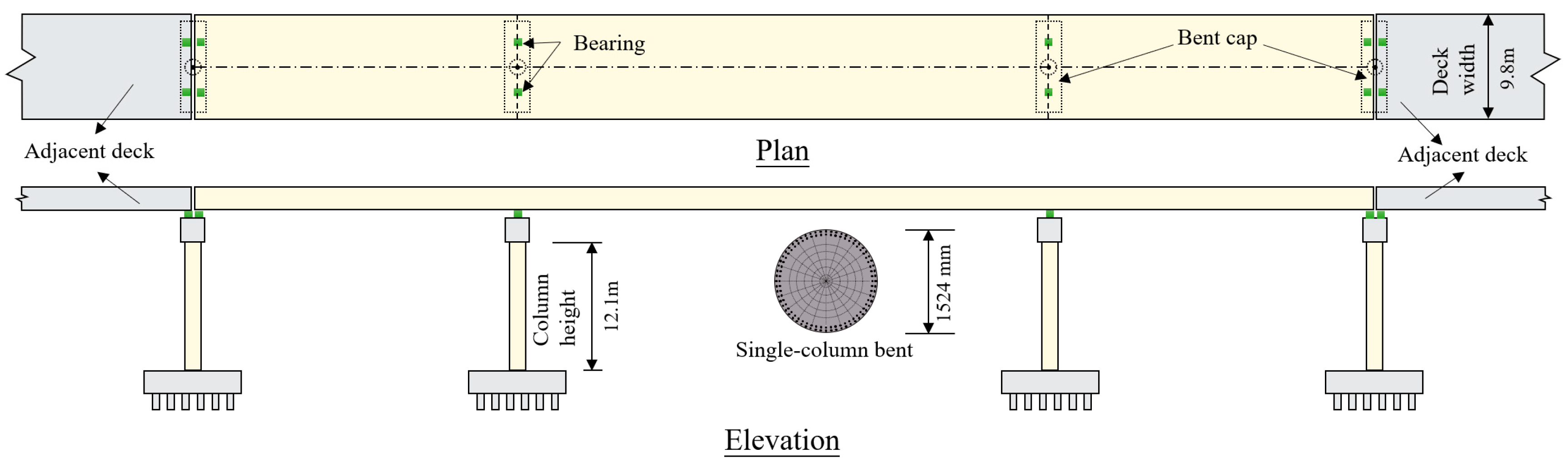
4.1. Description of Case Study Bridge

A multi-span RC continuous girder bridge, a common type of highway bridge in China, is selected as the testbed structure for the AS fragility analysis. The bridge has three units, each consisting of three spans, and has a deck width of 9.8 m. The spans in the first and last units of the bridge were 30 m long each, and the length of the three middle spans in the central unit was chosen to be 30 m, 50 m, and 30 m, resulting in an overall bridge length of 290 m. Each bridge column has a circular cross-section of 1524 mm in diameter along 12.10 m in height. Especially, 28 longitudinal steel bars of 32.8 mm diameter and transverse (spiral) reinforcing bars of 12 mm diameter and 89 mm spacing were used to reinforce the cross-section of the bridge columns. The compressive strength of concrete for columns is 33.0 Mpa, while the yield strength of reinforcing bars is 465 Mpa. The column aspect ratio was calculated well above 2.5, indicating the dominant flexural behavior of the column that, in turn, may lead to flexural failure due to the formation of a plastic hinge. The single-column bents and the box girder were linked with sliding rubber bearings. In each unit, one column can be found along the longitudinal direction designed to be the critical component; hence, fixed bearings have been placed at the top of those elements to decrease their vulnerability to structural failures. Figure 7 shows the thorough review of plans for the middle unit of the bridge, which is numerically modeled in this study.
The bridge was modeled using OpenSees Finite element code [38], as shown in Figure 8. It is noted that only the seismic performance of the middle unit of the bridge is investigated here, with the other two units being the boundary conditions. The critical column, i.e., the third column from the left, was modeled using the previous deterioration modeling technique. Additionally, the soil-structure interaction effects were considered. The first two natural vibration periods in the longitudinal direction of the FE model of the bridge were 0.99 s and 0.17 s, reflecting the bridge’s dominant first mode of vibration.

4.2. Strong Ground Motions

The calculation of the AS fragility requires using the bridge finite element model to perform response history analysis. To this end, mainshock-aftershock earthquake sequences were generated using a set of 30 earthquake ground motions already selected and used by Vamvatsikos and Cornell [39]. These earthquake motions, used herein both as mainshock and aftershock ground excitations, have been recorded at firm soil sites during past seismic events occurring in the western USA (California), with moment magnitude and closest distance to fault rupture ranging between 6.5 and 6.9 and 15 and 33 km, respectively. Additionally, the intensity of the selected earthquake motions, in terms of peak ground acceleration (PGA), varies between 0.04 and 0.63 g. It should be noted, though, that the measure used in the current study to quantify the intensity of earthquake motions is the first mode of spectral acceleration, Sa(T1), calculated at a damping ratio of 5%. The response spectra of the 30 ground motions are illustrated in Figure 9. The use of the 30 seismic motions, for which more details can be found elsewhere [39], eventually allowed the generation of 900 artificial mainshock-aftershock sequences since each strong ground motion was used both as mainshock and aftershock excitation. Such an artificial generation of mainshock–aftershock sequences has been widely adopted for relevant studies due to the difficulty of finding a sufficient number of recorded sequence events.

4.3. Definition of Damage States

The MBDI is employed herein as the seismic demand (also called engineering demand parameter, EDP) to quantify the structural damage induced to the multi-span RC continuous girder bridge when subjected to the seismic hazard. Along these lines, the correlation between physical damage and the currently proposed MBDI for various damage states needs to be established to facilitate the fragility calculation, especially to enable the numerical realization of different levels of damaged structures. This study categorizes the damage as minor, moderate, and extensive, while the last damage level adopted herein corresponds to the collapse.
The correspondence between the physical damage and the damage states, the latter defined in terms of MBDI, are shown in Table 1. The maximum drift ratio for each damage state can be obtained first through monotonic pushover analysis on the intact numerical model. Step 1 and Step 2 are introduced in detail in Section 2.2. The pushover result is illustrated in Figure 10a. The maximum drift ratio corresponding to each damage state can be determined numerically when it reaches the physical damage. According to the pushover result, the maximum drift ratio for each damage state is 0.0446, 0.0784, 0.1035, and 0.1286, respectively, as listed in Table 1. Based on the above, Step 3, Step 4, and Step 5, introduced in detail in Section 2.2, are carried out to obtain the values of MDBI corresponding to each limit state, as shown in Figure 10b. In Step 3, a monotonic pushover is conducted as the target load until it reaches the maximum drift ratio corresponding to a specific damage state, then unloaded until zero force. In Step 4, conduct a back-to-back monotonic pushover analysis in the same direction as the structural model until collapse. In Step 5, the values of MDBI corresponding to each limit state are calculated according to Equation (3). Finally, the threshold of the MBDI corresponding to the damage states are 0.02, 0.21, 0.57, and 1 for minor damage, moderate damage, extensive damage, and collapse, respectively.

5. Aftershock Fragility Assessment

5.1. The B2B-IDA Methodology for Aftershock Fragility Assessment

The incremental dynamic analysis (IDA) approach is widely used to generate fragility curves. An IDA involves a series of nonlinear time-history analyses of the structure subjected to incrementally increasing ground excitations. The intensity of each ground motion record in the ensemble is scaled to multiple levels to force the structure to undergo the entire range of behavior, from elastic to inelastic and finally to collapse.
The engineering community has developed different numerical schemes to assess AS fragility [6,7,8,9,10,11,12,13,14,15,16,17,18]. The latter can be mainly classified according to how the mainshock damage and the assessment of the post-mainshock capacity are simulated. Among those schemes, the so-called back-to-back incremental dynamic analysis (B2B-IDA) framework is widely used to calculate AS fragility of structural systems of varying size, geometry, material, importance, and complexity [10]. According to the B2B-IDA framework, post-mainshock damaged structure simulation is facilitated by incrementally scaling each mainshock strong ground motion until a specific level of damage is induced. Next, the AS fragility curves can be generated by performing IDA on the mainshock-damaged structure under a set of selected aftershock excitations.
This paper employs the B2B-IDA methodology to generate AS fragility curves. The process involves the following steps:
(1)
First, scale each mainshock incrementally to determine the intensity of the mainshock to induce the structure to reach exactly each specified damage state.
(2)
Second, perform a nonlinear time history analysis of the structure in each post-mainshock damage state subjected to mainshock-aftershock sequences (so-called “back-to-back” dynamic analyses). The mainshock serves as a means to induce the structure to sustain a certain level of post-mainshock damage, while the aftershock is scaled incrementally to calculate the AS fragility according to the EDP during the aftershock.
(3)
Last, determine the probability distribution of aftershock intensity values associated with each post-aftershock damage state conditioned on each post-mainshock damage state over all the 900 pairs of specific mainshock-aftershock sequences.

5.2. Aftershock Fragility Results

Scaling an earthquake record to obtain a realization of the building in each post-mainshock damage state is an iterative process, and the MBDI is used as EDP in the process. The intensities of the mainshocks to induce each damage state are firstly listed in Table 2.
Based on these, the back-to-back nonlinear time history analysis (NTHA) of the structure subjected to mainshock-aftershock sequences is performed. The AS fragility curves for each post-mainshock damage state are generated through the probability distribution of the EDPs obtained from 900 artificial mainshock-aftershock sequences. The IDA curves of the structure subjected to aftershocks conditioned on each post-mainshock damage state are shown in Figure 11. In the IDA method, the probability distribution of the EDPs for each damage state over all the 900 seismic sequences is assumed to be lognormal distribution. It must be validated through the hypothesis-testing method, e.g., the Kolmogorov–Smirnov test. The AS fragility curves are determined as the cumulative distribution function (CDF) of the EDPs in terms of the intensity of the aftershock. The IDA curves of the structure subjected to aftershocks conditioned on each post-mainshock damage state are shown in Figure 11. It is found that the aftershock IDA curves have a distinct upward tendency around the damage state corresponding to the mainshock damaged state. This phenomenon is even more evident for the higher structural damage sustained during the mainshock. Moreover, by comparing the IDA curves in the three subfigures, it is also found that the more severe damage caused by the mainshock, the lower the seismic intensity of the aftershock required to cause a certain degree of damage.
Figure 12 compares the AS fragility conditioned on different mainshock-damage states. As shown in Figure 12a, only the minor-damage aftershock fragility for the intact mainshock-damage state varies with the AS intensity, and the fragility for other mainshock-damage states turns out to be 1.0 constantly. This is because the structure already experienced a higher level than the minor damage due to the mainshock and can only sustain a greater extent of damage after an aftershock. Along this line, it is also observed that the moderate aftershock fragility for the moderate and extensive mainshock-damaged structure in Figure 12b and the extensive aftershock fragility for the extensive mainshock-damaged structure in Figure 12c are constantly 1.0. For others, the aftershock fragility curves increase with the AS intensity. In addition, it is also found that the higher the damage sustained during the mainshock, the greater the probability that the bridge will exhibit a more severe damage state when subjected to an aftershock of a given intensity. For example, Figure 12d compares the collapse fragility conditioned on the different mainshock-damage states. Specifically, when an aftershock with an intensity of 3.0 g occurs, the probability for the structure in a minor damage state (due to the mainshock) to collapse is 0.2. If the structure sustains extensive damage from the mainshock, the probability of collapse will sharply rise to 0.78. Therefore, the post-mainshock damage level will significantly influence the vulnerability of the structure to withstand an aftershock. In other words, when a structure sustains a higher damage level from a mainshock, it will be much more fragile. A similar trend can also be found in Figure 12a–c.

6. Validation of MBDI as EDP for Aftershock Fragility

In order to validate the effectiveness of the MBDI as a predictor of AS fragility, the assessment results are compared with those obtained from using the maximum drift ratio as EDP, one of the most widely used displacement-based damage indices [10].
The effectiveness of damage indices as predictors of AS fragility is evaluated in terms of their ability to reduce the deviation of collapse capacity of the structure when simulating a specific damage state using different mainshocks. The collapse capacity under an earthquake record herein is defined as the smallest ground motion spectral acceleration (at T1 and a damping ratio of 5%) of the record that would induce localized or complete structural collapse in an aftershock. Along these lines, the collapse capacity of a structure can be defined as the mean value of the collapse capacities under a number of ground motions. The deviation of collapse capacity concerned above is quantified via the coefficient of variation, COV (i.e., COV = σ/µ, where σ and µ are the standard deviation and the arithmetic mean value). σ and µ are calculated statistically based on the collapse capacities derived from using different mainshocks to induce a specific damage state. The same set of 30 aftershocks, as mentioned in Section 4, is used in this study to determine the collapse capacities.
Figure 13 illustrates the outcome for the mainshock-damage structure in minor, moderate, and extensive damage states (DS0 = 1, 2, 3) obtained via MBDI and the maximum drift ratio, with each column representing the COV of the residual capacities for the set of 30 mainshocks that induce damage and collapse by each aftershock. The comparison shows that the COVs for MBDI are generally lower than using the maximum drift ratio. In addition, the difference between the COVs via the two damage indices becomes more significant as the mainshock-damage level increases. The lower trend of the COVs for MBDI, when the structure sustains extensive damage from the mainshocks, shows a stronger relationship between MBDI and the residual capacity and therefore demonstrates the advantage of MDBI over maximum drift ratio in simulating severe damage. Based on the above discussion, it is concluded that MBDI, in this case, is a better damage index predictor of AS fragility.

7. Summary and Conclusions

This study presents an FE-based damage evaluation methodology for continuous girder bridges used to develop AS fragility curves based on post-mainshock damage conditions. It integrates a combined damage index that accounts for multiple factors associated with cumulative damage, an FE-based quantification procedure, and the supporting deterioration modeling technique. The proposed combined damage index (MBDI) is a modified version based on the damage model developed by Bracci. The FE-based quantification procedure is developed, in which back-to-back monotonic pushover analysis is required. For the deterioration modeling technique, the lumped plastic numerical model of bridge columns is established, consisting of three elements: a zero-length rotation spring at the bottom of the column, a rigid element, and fiber-based elements. The IMK hysteretic model captures the deterioration behaviors under MS-AS sequences. The process of determining the parameters for IMK material (including both the backbone curve and the cyclic deterioration parameters) is introduced. The proposed damage measure methodology can consider nearly all the critical factors related to cumulative damage, such as stiffness and strength deterioration, peak displacement, and residual displacement. A multi-span RC continuous girder bridge is studied and modeled to demonstrate the proposed method using OpenSees. The B2B-IDA framework is applied using 900 MS-AS synthetic sequences generated from 30 earthquake records to calculate the AS fragility conditioned on a different level of post-mainshock damage. The influence of the post-mainshock damage states on AS fragility is investigated. The following broad conclusions emerge.
(1)
The aftershock fragility results show that the higher the damage sustained during the mainshock, the greater the probability that the bridge will exhibit a more severe damage state when subjected to an aftershock of a given intensity.
(2)
The proposed damage index’s effectiveness is investigated in the second part of the study. The AS fragility results obtained via MBDI are compared with those via maximum drift ratio in terms of the ability to reduce the variation of residual capacities obtained using different mainshocks to induce a specific damage state but collapse by the same aftershock. The comparison shows a more robust relationship of MBDI with the residual capacity and therefore demonstrates that MBDI is a better damage index predictor of AS fragility.
(3)
The major contribution of the proposed damage measure methodology is the refinement of an effective predictor for evaluating cumulative damage for AS fragility assessment. It enables quantitative evaluation of the increased vulnerability of damaged RC bridges while significantly reducing the variation derived from using different mainshocks to simulate structural damage.
(4)
It is noted that the deterioration modeling technique proposed in this study fits well with the structures in which the plastic hinges generate only in finite and fixed positions under external loading. For those structures with uncertain plastic hinge zone, developing other applicable deterioration modeling methods is necessary. Whether the quantification procedure for the MBDI is still suitable needs to be discussed in future studies.
(5)
The proposed damage quantification methodology can be extended to other AS fragility analysis frameworks, such as the IDA-Cloud framework. In future studies, the methodology should be adapted to explore its effectiveness in developing AS fragility using the cloud method.

Author Contributions

Conceptualization, Z.W., J.G., and X.D. (Xinzhi Dang); methodology, Z.W.; investigation, Z.W. and J.G.; case study design copyright, X.D. (Xiaowei Deng), X.L., X.D. (Xinzhi Dang); writing—original draft preparation, Z.W.; writing—review and editing, Z.W. and J.G.; formal analysis, Z.W.; validation, Z.W.; discussion, Z.W., J.G., X.D. (Xiaowei Deng), X.L., X.D. (Xinzhi Dang). All authors have read and agreed to the published version of the manuscript.

Funding

This research was funded by the National Key Research and Development Program of China (2019YFE0112300), the Shanghai Post-doctoral Excellent Program (2021333), the Post-doctoral Innovation Practice Base Program of Shanghai Yangpu District, the Shanghai Rising-Star Program (21QB1406000), and the National Natural Science Foundation of China (51978512).

Data Availability Statement

Not applicable.

Conflicts of Interest

The authors declare no conflict of interest.

References

  1. Goda, K. Record selection for aftershock incremental dynamic analysis. Earthq. Eng. Struct. Dyn. 2015, 44, 157–162. [Google Scholar] [CrossRef]
  2. Goda, K.; Taylor, C.A. Effects of aftershocks on peak ductility demand due to strong ground motion records from shallow crustal earthquakes. Earthq. Eng. Struct. Dyn. 2012, 41, 2311–2330. [Google Scholar] [CrossRef]
  3. Knopoff, L.; Gardner, J. Higher seismic activity during local night on the raw worldwide earthquake catalogue. Geophys. J. Int. 1972, 28, 311–313. [Google Scholar] [CrossRef] [Green Version]
  4. Hosseinpour, F.; Abdelnaby, A.E. Fragility curves for RC frames under multiple earthquakes. Soil Dyn. Earthq. Eng. 2017, 98, 222–234. [Google Scholar] [CrossRef]
  5. Villaverde, R. Methods to Assess the Seismic Collapse Capacity of Building Structures: State of the Art. J. Struct. Eng. 2007, 133, 57–66. [Google Scholar] [CrossRef] [Green Version]
  6. Bazzurro, P.; Cornell, C.A.; Menun, C.; Motahari, M. Guidelines for seismic assessment of damaged buildings. In Proceedings of the 13th World Conference on Earthquake Engineering, Vancouver, BC, Canada, 1–6 August 2004; p. 1708. [Google Scholar]
  7. Maffei, J.; Telleen, K.; Nakayama, Y. Probability-Based Seismic Assessment of Buildings, Considering Post-Earthquake Safety. Earthq. Spectra 2008, 24, 667–699. [Google Scholar] [CrossRef]
  8. Polese, M.; Di Ludovico, M.; Prota, A.; Manfredi, G. Damage-dependent vulnerability curves for existing buildings. Earthq. Eng. Struct. Dyn. 2013, 42, 853–870. [Google Scholar] [CrossRef] [Green Version]
  9. Luco, N.; Bazzurro, P.; Cornell, B.Y.C.A. Dynamic Versus Static Computation Of The Residual Capacity Of A Mainshock-damaged Building To Withstand An Aftershock. In Proceedings of the 13th World Conference on Earthquake Engineering, Vancouver, BC, Canada, 1–6 August 2004. [Google Scholar]
  10. Raghunandan, M.; Liel, A.B.; Luco, N. Aftershock collapse vulnerability assessment of reinforced concrete frame structures. Earthq. Eng. Struct. Dyn. 2015, 44, 419–439. [Google Scholar] [CrossRef]
  11. Li, Q. Mathematical Formulation of Tools for Assessment of Fragility and Vulnerability of Damaged Buildings. Ph.D. Thesis, Tsinghua University, Beijing, China, 2006. [Google Scholar]
  12. Jeon, J.-S.; DesRoches, R.; Lowes, L.N.; Brilakis, I. Framework of aftershock fragility assessment-case studies: Older California reinforced concrete building frames. Earthq. Eng. Struct. Dyn. 2015, 44, 2617–2636. [Google Scholar] [CrossRef]
  13. Gaetani d’Aragona, M.; Polese, M.; Elwood, K.J.; Baradaran Shoraka, M.; Prota, A. Aftershock collapse fragility curves for non-ductile RC buildings: A scenario-based assessment. Earthq. Eng. Struct. Dyn. 2017, 46, 2083–2102. [Google Scholar] [CrossRef]
  14. Wen, W.; Zhai, C.; Ji, D.; Li, S.; Xie, L. Framework for the vulnerability assessment of structure under mainshock-aftershock sequences. Soil Dyn. Earthq. Eng. 2017, 101, 41–52. [Google Scholar] [CrossRef]
  15. Ebrahimian, H.; Jalayer, F.; Asprone, D.; Lombardi, A.M.; Marzocchi, W.; Prota, A.; Manfredi, G. A performance-based framework for adaptive seismic aftershock risk assessment. Earthq. Eng. Struct. Dyn. 2014, 43, 2179–2197. [Google Scholar] [CrossRef]
  16. Jalayer, F.; Ebrahimian, H. Seismic risk assessment considering cumulative damage due to aftershocks. Earthq. Eng. Struct. Dyn. 2017, 46, 369–389. [Google Scholar] [CrossRef]
  17. Shokrabadi, M.; Burton, H.V. Risk-based assessment of aftershock and mainshock-aftershock seismic performance of reinforced concrete frames. Struct. Saf. 2018, 73, 64–74. [Google Scholar] [CrossRef]
  18. Trevlopoulos, K.; Guéguen, P. Period elongation-based framework for operative assessment of the variation of seismic vulnerability of reinforced concrete buildings during aftershock sequences. Soil Dyn. Earthq. Eng. 2016, 84, 224–237. [Google Scholar] [CrossRef]
  19. Shinozuka, M.; Kim, S.-H.; Kushiyama, S.; Yi, J.-H. Fragility curves of concrete bridges retrofitted by column jacketing. Earthq. Eng. Eng. Vib. 2002, 1, 195–205. [Google Scholar] [CrossRef]
  20. Sung, Y.-C.; Su, C.-K. Time-dependent seismic fragility curves on optimal retrofitting of neutralised reinforced concrete bridges. Struct. Infrastruct. Eng. 2011, 7, 797–805. [Google Scholar] [CrossRef]
  21. Tolentino, D.; Márquez-Domínguez, S.; Gaxiola-Camacho, J.R. Fragility assessment of bridges considering cumulative damage caused by seismic loading. KSCE J. Civ. Eng. 2020, 24, 551–560. [Google Scholar] [CrossRef]
  22. Furtado, A.; Rodrigues, H.; Varum, H.; Arêde, A. Mainshock-aftershock damage assessment of infilled RC structures. Eng. Struct. 2018, 175, 645–660. [Google Scholar] [CrossRef]
  23. Zhai, C.-H.; Bao, X.; Zheng, Z.; Wang, X.-Y. Impact of aftershocks on a post-mainshock damaged containment structure considering duration. Soil Dyn. Earthq. Eng. 2018, 115, 129–141. [Google Scholar] [CrossRef]
  24. Poiani, M.; Gazzani, V.; Clementi, F.; Lenci, S. Aftershock fragility assessment of Italian cast–in–place RC industrial structures with precast vaults. J. Build. Eng. 2020, 29, 101206. [Google Scholar] [CrossRef]
  25. Li, Y.; Song, R.Q.; Van de Lindt, J.W. Collapse Fragility of Steel Structures Subjected to Earthquake Mainshock-Aftershock Sequences. J. Struct. Eng. 2014, 140, 1–10. [Google Scholar] [CrossRef]
  26. Baker, J.W.; Cornell, C.A. Vector-Valued Ground Motion Intensity Measures for Probabilistic Seismic Demand Analysis; Pacific Earthquake Engineering Research Center, College of Engineering, University of California: Berkeley, CA, USA, 2006. [Google Scholar]
  27. Park, Y.-J.; Ang, A.H.-S.; Wen, Y.K. Seismic damage analysis of reinforced concrete buildings. J. Struct. Eng. 1985, 111, 740–757. [Google Scholar] [CrossRef]
  28. Park, Y.-J.; Ang, A.H.-S. Mechanistic seismic damage model for reinforced concrete. J. Struct. Eng. 1985, 111, 722–739. [Google Scholar] [CrossRef]
  29. Williams, M.S.; Sexsmith, R.G. Seismic damage indices for concrete structures: A state-of-the-art review. Earthq. Spectra. 1995, 11, 319–349. [Google Scholar] [CrossRef]
  30. Bracci, J.; Reinhorn, A.; Mander, J.; Kunnath, S. Deterministic Model for Seismic Damage Evaluation of RC Structures; National Academies: Washington, DC, USA, 1989; NCEER-89-0033. [Google Scholar]
  31. Ibarra, L.F.; Medina, R.A.; Krawinkler, H. Hysteretic models that incorporate strength and stiffness deterioration. Earthq. Eng. Struct. Dyn. 2005, 34, 1489–1511. [Google Scholar] [CrossRef]
  32. Haselton, C.B.; Deierlein, G.G. Assessing Seismic Collapse Safety of Modern Reinforced Concrete Moment-Frame Buildings. Civ. Eng. 2008, 137, 481–491. [Google Scholar] [CrossRef] [Green Version]
  33. Abdelnaby, A.E. Fragility Curves for RC Frames Subjected to Tohoku Mainshock-Aftershocks Sequences. J. Earthq. Eng. 2018, 22, 902–920. [Google Scholar] [CrossRef]
  34. Berry, M.P.; Lehman, D.E.; Lowes, L.N. Lumped-plasticity models for performance simulation of bridge columns. ACI Struct. J. 2008, 105, 270–279. [Google Scholar]
  35. Hosseinpour, F.; Abdelnaby, A.E. Effect of different aspects of multiple earthquakes on the nonlinear behavior of RC structures. Soil Dyn. Earthq. Eng. 2017, 92, 706–725. [Google Scholar] [CrossRef]
  36. Lignos, D.; Krawinkler, H. Sidesway Collapse of Deteriorating Structural Systems Under Seismic Excitations; Report No. TB 172; John, A., Ed.; Blume Earthquake Engineering Research Center, Department of Civil and Environmental Engineering, Stanford University: Stanford, CA, USA, 2009. [Google Scholar]
  37. Lignos, D.G.; Krawinkler, H. Deterioration modeling of steel components in support of collapse prediction of steel moment frames under earthquake loading. J. Struct. Eng. 2010, 137, 1291–1302. [Google Scholar] [CrossRef]
  38. OpenSees. Open System for Earthquake Engineering Simulation. Available online: http://opensees.berkeley.edu/ (accessed on 7 October 2022).
  39. Vamvatsikos, D.; Cornell, C.A. Incremental dynamic analysis. Earthq. Eng. Struct. Dyn. 2002, 31, 491–514. [Google Scholar] [CrossRef]
Figure 1. Schematic illustration of the MBDI [29].
Buildings 12 01675 g001
Figure 2. Flow chart of the proposed procedure for the FE−based quantification of MBDI.
Buildings 12 01675 g002
Figure 3. Schematic illustration of the MDBI quantification procedure: (a) Monotonic pushover curve of the intact structure; (b) Monotonic post−earthquake pushover curve of the damaged structure.
Buildings 12 01675 g003
Figure 4. Procedure for determining the backbone curve parameters: (a) the fiber-based column model, (b) conducting monotonic pushover analysis to determine the parameters for the zero-length rotation spring, and (c) the final lumped plasticity column model.
Buildings 12 01675 g004
Figure 5. Schematic illustration of simulating the backbone curve with the quad-linear model.
Buildings 12 01675 g005
Figure 6. Validation with quasi−static test results.
Buildings 12 01675 g006
Figure 7. Schematic illustration of the bridge layout.
Buildings 12 01675 g007
Figure 8. Numerical model of the bridge and its various components.
Buildings 12 01675 g008
Figure 9. The response spectra of the 30 ground motions.
Buildings 12 01675 g009
Figure 10. (a) The pushover curves for the study case, and (b) the definition of damage states in terms of Maximum Drift ratio and MBDI.
Buildings 12 01675 g010
Figure 11. IDA curves of aftershocks for the bridge in minor, moderate, and extensive damage states.
Buildings 12 01675 g011
Figure 12. Aftershock fragility curves for different damage states (a) minor damage, (b) moderate damage, (c) extensive damage, and (d) collapse damage conditioned on different mainshock-damage states.
Buildings 12 01675 g012
Figure 13. Variability of collapse capacity derived from different mainshocks that induce initial damage states via different damage indices.
Buildings 12 01675 g013
Table 1. Damage states defined in the current study.
DSLimit StatePhysical DamageMaximum Drift RatioMBDI
DS1MinorSpalling of cover concrete0.330.02
DS2ModerateCore crushing0.570.21
DS3ExtensiveBar buckling0.760.57
DS4CollapseLarge drift0.941.00
Table 2. Seismic intensities of the mainshocks to induce each damaged state.
Ground MotionSeismic Intensity (Sa(T1),g)
DS1DS2DS3DS4
11.302.242.963.23
21.703.423.883.95
31.562.602.903.06
41.882.983.714.24
51.772.632.862.91
61.132.652.852.93
71.495.456.256.58
81.332.032.162.24
90.981.281.601.69
101.501.641.681.70
111.111.581.892.18
121.052.223.774.96
131.472.422.672.80
140.751.141.361.54
151.251.671.892.02
160.741.111.281.50
171.512.302.913.29
181.041.261.361.44
191.402.162.803.22
201.161.581.862.03
211.122.214.154.84
221.322.102.633.52
231.453.736.817.71
243.384.605.015.25
252.264.424.835.00
261.442.282.793.22
271.061.471.731.94
280.861.101.201.26
291.001.652.032.24
300.811.051.241.35
Publisher’s Note: MDPI stays neutral with regard to jurisdictional claims in published maps and institutional affiliations.

