Abstract
In this paper, we present an original experimental investigation on a pull-out test of a blind rivet from the external facing of sandwich panels with various core layer materials (polyisocyanurate foam, mineral wool, and expanded polystyrene). The blind rivets were subjected to an axial and eccentric tensile force introduced as static and quasi-cyclic loading. The statistical sample size was 5. The laboratory results depicted that the core layer of a sandwich panel influenced the load-displacement path of the investigated blind rivet connections, regardless of the nature of the load (static, quasi-cyclic) and the point of the load application (axial, eccentric). It was observed that the blind connection with the polyisocyanurate foam core sandwich panel was characterized by a reduction of both the capacity and the secant stiffness when compared with the blind connection with the mineral wool or the expanded polystyrene core sandwich panels. Moreover, the tested connections demonstrated that the eccentric load gave a higher flexural stiffness than the axial load and that the quasi-cyclic load did not reduce their stiffness and capacity.
1. Introduction
The research refers to the use of blind rivets with sandwich panels. The sandwich panels considered in this paper consist of two thin and stiff external facings and a thick and soft core. The facings are made of high strength material such as steel, aluminum, or laminate. The core is made of thermal insulation materials, namely polyisocyanurate foam (also referred to as PIR foam), mineral wool, or expanded polystyrene. These types of composite structures are used in structural engineering applications, such as roofs and wall cladding elements. When using the typical materials for sandwich panel layers, the core/facing thickness ratios vary from 60 to 500, the facing/core density ratios vary from 10 to 600, while the facing/core Young modulus ratios vary from 600 to 95,000 (see Table 1 and Table 2).

Table 1.
Geometrical and mechanical properties of the sandwich panel core materials.
Table 2.
Geometrical and mechanical properties of the sandwich panel facing materials.
The values presented above highlight a clear division of functions of individual layers in the sandwich panels; namely, due to its high thickness the core made of “soft” material provides the distance for very thin external facings, which have a high strength and are made of stiff material. In consequence, from a mechanical point of view, the bending stiffness is directly and indirectly provided by the facings and the core, respectively, while the shear stiffness is provided only by the core layer. The sandwich panels’ theoretical background on their mechanics and theories can be found in [7,8,9]. From a functional point of view, the facings provide protection from atmospheric factors such as wind, snowfall, rainfall, moisture, and UV radiation, while the core provides appropriate thermal and acoustic insulation properties. Therefore, the sandwich panels can be characterized by a high load-bearing capacity coupled with a small weight and good thermal insulation properties. In spite of the layered structure and the number of failure mechanisms [7,10], the sandwich panels often constitute objects that provide mass, geometry, or cost optimization [11,12,13].
One of the sandwich panels’ disadvantages involves the problem of connecting them with buildings’ structural elements (steel, reinforced concrete, or timber), suspending (floor, roof panels) or hanging (wall panels), the building infrastructural elements, and this could reduce the sandwich panels’ overall thermal insulation abilities. This is because of the widespread use of through-drilling fasteners, which penetrate the thermal insulation layer and create point thermal bridges. The parametric analysis of this effect, i.e., the use of through-drilling fasteners, is widely discussed in [14,15]. The authors [14] quantified this “thermal bridging effect”, and they found that neglecting point thermal bridges in building cladding systems can lead to an underestimation of 5% to 20% of the actual heat flow. In [15], the significant dependency of the point thermal bridges on the thermal conductivity of the bearing layer material and its thickness was presented. Another disadvantage of through-drilling fasteners is the laboriousness during installation. Through-drilling fastener usage requires an additional supporting structure to hang or suspend the building’s infrastructural elements (banners, ads, control and/or distribution boxes, air conditioning components, and others). This leads to an increase of the material and assembly costs of the whole structure.
In many cases, the alternative solution to using through-drilling fasteners may be blind rivets, whose use is not common so far. The use of blind rivets in sandwich panels allows one to avoid the abovementioned disadvantages related to through-drilling fasteners (see Figure 1).
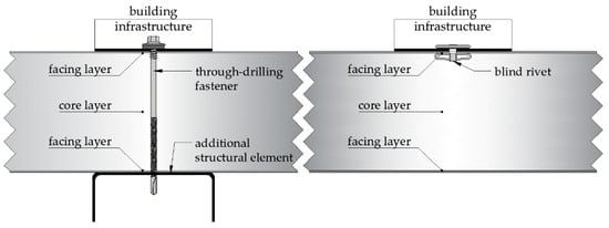
Figure 1.
Schemes of the connections of the building infrastructure with the sandwich panel via a through-drilling fastener and a blind rivet.
First, the blind rivet could connect the additional element of the building infrastructure with a single (internal or external) sandwich panel, facing in such a way that the core layer, which provides thermal insulation, is not penetrated from throughout. Second, this type of connection does not need an additional supporting structure, and the installation process id done from one side only. In this type of the connection, the blind rivets would be subjected to tension, compression, and shear loading. It is worth emphasizing that nowadays there are no standard recommendations referring to the use of blind rivets with sandwich panels. Moreover, in the subject’s literature, there are only a few references to the use of blind rivets with composite sandwich panels. The first information on the use of blind rivets (starting from the 60 s) can be found in patent documents [16,17,18]. Blind fastening systems for laminated composites used in aircraft solutions were widely presented in [19]. In [20], the experimental approach of using both blind rivets and mechanical lock fasteners with sandwich composite panels was presented. The sandwich panels considered in the mentioned paper consisted of a honeycomb core and laminated facings made of glass, graphite, and Kevlar fibers in an epoxy matrix. The fasteners were subjected to a static axial pull-out and shear loading. The continuation of the research presented in [20] considers the fatigue behavior of the connections and can be found in [21,22]. The subject literature presented above refers to sandwich composite structures not used in building solutions. The building applications for this type of connection were recently discussed in [23], which presented different possibilities for introducing forces into sandwich panels with flat, lightly profiled, and profiled facings by means of one-side fasteners. An experimental investigation of the use of blind rivets in sandwich panels used as building cladding elements, with steel or laminate facing and PIR foam core, was discussed in [4]. In [4], three- and four-fold blind rivets subjected to an axial pull-out static load were investigated. Apart from the influence of the facing material (steel, laminate) on the mechanical response of the blind connection, the importance of the primer layer applied between the external metal facing and the PIR foam core was analyzed. Additionally, a validated finite element model in the elastic range of the mechanical response of the blind connection was presented in [4]. This article is a continuation of the research presented in [4], extending it to the aspect of the load nature (static, quasi-cyclic), the aspect of the load type (axial, eccentric), and the aspect of the core layer material (PIR foam, mineral wool, and expanded polystyrene). The presented research is original because, in this range, sandwich panels with installed blind rivets subjected to a static vs. quasi-cyclic load and an axial vs. eccentric load have not been presented or discussed in the literature before.
2. Materials and Methods
In this paper, we present an experimental investigation on a pull-out test of blind rivets subjected to an axial and an eccentric tensile force introduced as a static and a quasi-cyclic loading. The blind rivets were pulled-out from the lightly profiled facing of sandwich panels with various core layer materials, i.e., PIR foam, mineral wool, and expanded polystyrene (see Figure 2a–c respectively). The sandwich panel facing was made of zinc-coated steel. The parameters of the sandwich panel layers used in the experiment are presented in Table 3.
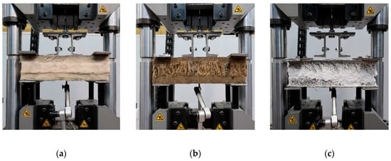
Figure 2.
Test bed with test samples. Sandwich panel made of: (a) PIR foam core, (b) mineral wool core, and (c) expanded polystyrene core.
Table 3.
Nominal geometrical and mechanical properties of the sandwich panel layers used in the experiment.
The sandwich panel samples were of a rectangular shape, measuring 250 mm and 350 mm in width and length, respectively. Along the width, fixed boundary conditions were assumed. In the geometrical middle of the facing, the blind rivet was attached into the test bed holder via a U-shape adapter with a thickness of 1.5 mm. The test bed holder was fixed into the Instron Satec testing machine via in-head grips for round specimens. The scheme of the test bed is depicted in Figure 3.
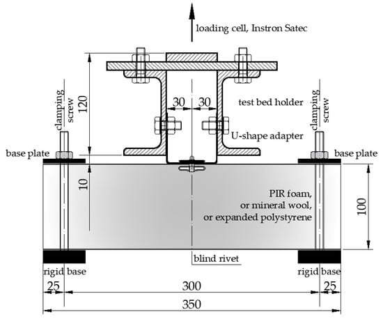
Figure 3.
Scheme of the test bed (dimensions are given in millimeters).
In the experiment, an aluminum trifold-type blind rivet was used. This type of blind rivet is characterized by a wide grip range, due to the hat bulges, and by a pull-through resistance: it has three folds that distribute the pressure over a wider surface area. The rivet consists of a hat with a diameter of 4.76 mm (3/16′′), with a neoprene washer and a mandrel (see Figure 4).
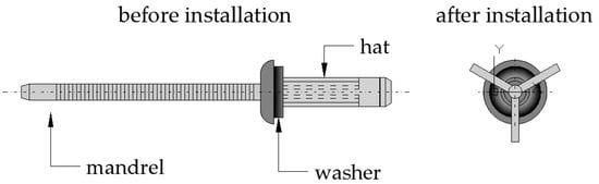
Figure 4.
Scheme of a blind rivet before and after installation.
In Table 4, four cases of laboratory tests are summarized. The samples with the PIR foam and mineral wool layer were used in all configurations, A, B, C, and D, while the samples with expanded polystyrene were used in two configurations, A and B. Five samples were prepared for each case/core configuration, and thus the research covered a total of 50 tests. The laboratory trials were conducted on an Instron Satec testing machine with a Hottinger Baldwin Messtechnik (HBM) measuring amplifier. The load was applied with a 2 mm/min unit-cell speed (displacement control). During the experiment, the load and the displacement of the unit cell were measured. Additionally, the deflection of the sandwich panel’s bottom facing was recorded with an inductive standard displacement transducer with a measuring range of up to 20 mm (1-WA/20MM-T). The measurement of the bottom facing’s deflection showed that the influence of this deflection on the total measured displacement of the blind rivet was equal to: +1.0% for the PIR foam core, +1.1% for the expanded polystyrene core, and +1.5% for the mineral wool core. Therefore, this effect in the analysis was neglected.
Table 4.
Set of laboratory experiments.
In Figure 5, the displacement control program for quasi-cyclic loading is presented (the continuous line refers to the sandwich panels with a PIR foam and mineral wool core, while the dashed line refers to the sandwich panel with expanded polystyrene).
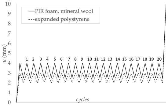
Figure 5.
Displacement control program for quasi-cyclic loading.
3. Results
In this section, the presentation of the experimental results of the four cases distinguished in Table 4 is given. There are 10 different arrangements for the tests:
- two cases (A, B) with three types of a core layers, i.e., PIR foam, mineral wool, and expanded polystyrene (load-displacement curves are depicted in Figure 6),
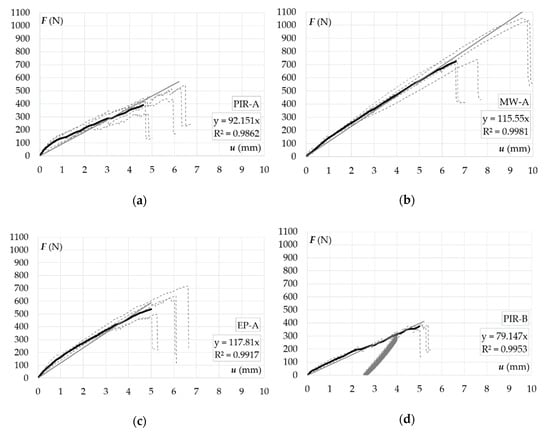
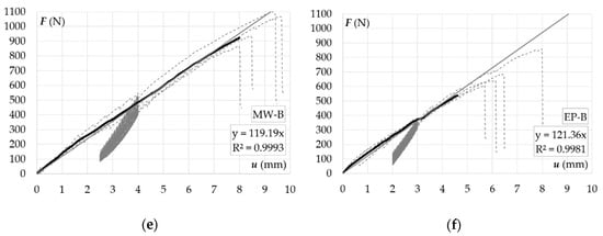 Figure 6. Axial pull-out of a blind rivet from a sandwich panel facing: (a) static pull-out from a panel with a PIR foam core, (b) static pull-out from a panel with a mineral wool core, (c) static pull-out from a panel with expanded polystyrene, (d) quasi-cyclic pull-out from a panel with a PIR foam core, (e) quasi-cyclic pull-out from a panel with a mineral wool core, (f) quasi-cyclic pull-out from a panel with expanded polystyrene.
 - two cases (C, D) with two types of core layers, i.e., PIR foam and mineral wool (load-displacement curves are depicted in Figure 7).
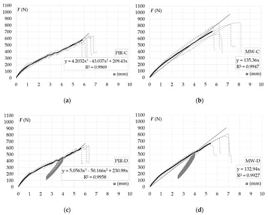 Figure 7. Eccentric pull-out of a blind rivet from a sandwich panel facing: (a) static pull-out from a panel with a PIR foam core, (b) static pull-out from a panel with a mineral wool core, (c) quasi-cyclic pull-out from a panel with a PIR foam core, (d) quasi-cyclic pull-out from a panel with a mineral wool core.
The following three thematic problems can be distinguished:
- influence of a core-layer material on the mechanical response of a pull-out of a blind rivet,
- influence of a quasi-cyclic load in relation to a static load on the mechanical response of a pull-out of a blind rivet,
- influence of an eccentric load in relation to an axial load on the mechanical response of a pull-out of a blind rivet.
In the graphs presented in Figure 6 and Figure 7, the thin grey dashed lines refer to particular trials, the thick black lines represent the average load-displacement curve of each type of test, while the continuous grey lines refer to the linear trend lines of the average load-displacement curves. Additionally, the trend line equation (linear function) and the coefficient of determination (R2) of each trend line are given.
The research revealed that the mechanical response of the axial pull-out of a blind rivet could be represented by a linear function y(x) = a·x, where (according to Figure 6) y(x) denotes a force F(u), x is a displacement u, and a is the slope of a linear function. The slope of a linear function can be obtained from the equations of the trend lines presented in Figure 6. Therefore, the two mean values of a, one for the sandwich panels with a PIR foam core (a1 = 85.65) and the other for the sandwich panels with mineral wool and expanded polystyrene cores (a2 = 118.75), provide the following relations:
The range of applicability of the linear formulas given in Equation (1) is limited by providing, for each type of core material, the characteristic value of the displacements uk corresponding to the maximal value of the axial forces. The displacement’s characteristic value uk is the 5% fractile value of the displacement population u determined using a 75% confidence limit, in accordance with [24]; see Equation (2) [25]:
where uk is the 5% fractile value of the population u, is the mean value of γ = ln(ui), k is the fractile value given in Table 5, and σγ is the standard deviation of γ given by Equation (3) [25]:
where n is the number of specimens and ui is the recorded test samples’ displacement corresponding to the maximal axial forces.
Table 5.
Fractile factor k, assuming a confidence level of 75% [24].
In Table 6, we present the characteristic values of uk for the axial pull-out, calculated according to Equations (2) and (3).
Table 6.
Axial pull-out—calculation of the characteristic values of the displacements uk (mm).
The forces Fi(uk), corresponding to the characteristic values of the displacements uk determined using a confidence limit of 75%, were obtained from the test data (columns 2–11 in the Table 7). For each core layer material, the mean values Fm(uk) from the forces Fi(uk) were calculated. The determined mean values of the forces Fm(uk) of the axially loaded blind connection make it possible to verify the correctness of the analytical formulas given in Equation (1). In the case of the formulas for the axially loaded blind connections according to Equation (1), one formula is given for panels with a PIR foam core and the other is given for panels with a mineral wool and expanded polystyrene core. The percentage difference between the value from the analytical formula and the mean value from the laboratory experiments is expressed by the χ parameter (see Table 7).
Table 7.
Axial pull-out—comparison of the force from laboratory tests: Fi(uk) [N], Fm(uk) [N] and analytical calculations F(uk) [N].
The research showed that the mechanical response of the eccentric blind rivet pull-out could be represented by a third-degree polynomial y(x) = a·x3 + b·x2 + c·x, where y(x) denotes a force F(u), x is the displacement u, and a, b and c are the constants of the third-degree polynomial. The two mean value sets of the third-degree polynomial constants, one set for the sandwich panels with a PIR foam core (a3 = 4.630, b3 = −46.602, and c3 = 220.205) and the second set for the sandwich panels with a mineral wool core (a4 = 2.576, b4 = −28.173, and c4 = 203.860), provide the following relations:
In Table 8, the characteristic values of uk for the eccentric pull-out, calculated according to Equations (2) and (3), are presented.
Table 8.
Eccentric pull-out—calculation of the characteristic values of the displacements uk (mm).
The determined mean value of the forces Fm(uk) of the eccentrically loaded blind connection makes it possible to verify the correctness of the analytical formulas given in Equation (4). In this case, according to Equation (4), one formula is given for panels with a PIR foam core and the other is given for panels with a mineral wool core. Similar to Table 7, in Table 9 the parameter χ, which expresses the percentage difference between the value from the analytical formula and the mean value of the eccentrically loaded blind connection, is presented.
Table 9.
Eccentric pull-out—comparison of the force from the laboratory tests: Fi(uk) (N), Fm(uk) (N) and the analytical calculations: F(uk) (N).
The parameters χ presented in Table 7 and Table 9 indicate that when using defined analytical formulas (Equations (1) and (4)), the response of a blind connection can be predicted at a 5% compliance level.
The structural behavior of the blind connection (blind rivet with sandwich panels) can be characterized by four parameters, namely strength, stiffness, deformation capacity, and failure energy. The strength defines the allowable load (elastic and ultimate) that can be applied via the blind connection to the sandwich panel. The stiffness of the connection (initial, secant) affects the level of loading that it should be designed for and determines its ultimate amount of failure energy as well as its deformation capacity. A connection with a low stiffness does not transfer a high failure energy. The deformation capacity characteristic is more qualitative. Ductile connections that have a great deformation capacity may provide an overall safety for connections that become overloaded. The area below the load-displacement curve expresses the amount of failure energy that must be provided to the connection for it to reach its capacity. In Figure 8, these four parameters are depicted.
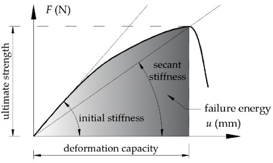
Figure 8.
Blind rivet in sandwich panels – connection characteristic.
The quantitative comparison of the parameters abovementioned were examined for samples with a mineral wool core layer. For this purpose, the mean values from the tests for the four load cases described in Section 2 (A, B, C, and D) are depicted in Table 10. In Table 10, kini represents the initial stiffness, ksec represents the secant stiffness (for ta displacement range of u ∈ (0.0–4.0 mm), F(u = 4.0) represents the force, which refers to the 4-mm displacement of the connection, and AF represents the energy that has to be provided to the system (connection) in order to obtain a 4.0-mm deformation.
Table 10.
Quantitative comparison of the results for the test samples with the mineral wool core.
The results presented in Table 10 reveal the quantitative influence of the various load arrangements on the samples with the mineral wool core layer. It can be observed that the nature of the loading (static vs. quasi-cyclic) does not influence the initial stiffness, secant stiffness, and failure energy of the blind connection. On the other hand, the type of loading (axial vs. eccentric) influences the mechanical response of the blind connection in such a way that, for eccentrically loaded blind connections:
- the initial stiffness is about 40% larger,
- the secant stiffness is about 10% larger, and
- the failure energy is about 15% larger.
The research showed the influence of the sandwich panel core layer material on the structural behavior of the blind connection. In all cases, regardless of the type of core layer and nature of the load, the limit point on the load-displacement curve was associated with the same failure mechanism, i.e., with the delamination of the facing from the core layer (see Figure 9).
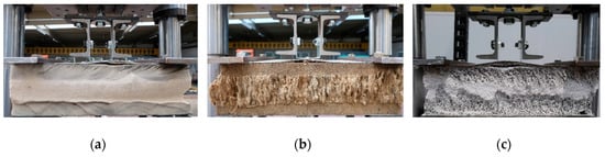
Figure 9.
Failure mechanisms of the blind connection in sandwich panels: (a) core made of PIR foam, (b) core made of mineral wool, and (c) core made of expanded polystyrene.
In the case of the PIR foam core layer, the delamination was initiated in the vicinity of the blind rivet, and was then propagated to the free edge of the rectangular sample. The moment of initiation of the failure was demonstrated by a significant change of the stiffness of the load-displacement curve (for example, see Figure 6a), while the propagation along the width was demonstrated by the sudden drop in the load capacity. In the case of the core layer made of mineral wool and expanded polystyrene, the delamination was simultaneous along the whole width of the rectangular sample, and thus the load-displacement curves showed a smooth course without sudden changes in the slope (for example, see Figure 6b,c). This means that the full integration between the core and the facing was demonstrated until the limit point (ultimate strength, see Figure 8) by the mineral wool and the expanded polystyrene, while in the case of the PIR foam it was limited until the point of significant change in the slope of the load-displacement curve. This explains why the average load-displacement charts of the blind connection tests with the mineral wool and the expanded polystyrene core layer overlap along the entire course, while in the case of the tests with the PIR foam core layer, the chart overlap is limited (see Figure 10).
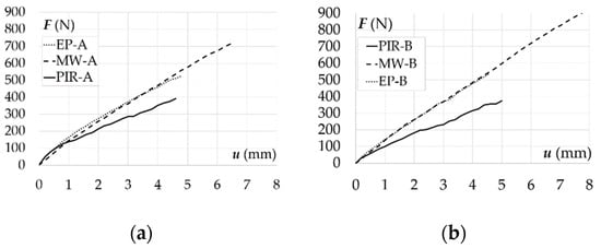
Figure 10.
Load-displacement relations for the pull-out of a blind rivet installed in sandwich panels with various core materials: (a) static axial load—case A, (b) quasi-cyclic axial load—case B.
Due to the lower strength of the adhesion between the expanded polystyrene and the facing, the load capacity of the blind connection with this core material was lower than in the case of the mineral wool core. The blind connection with the PIR foam core sandwich panel was characterized by the lowest load capacity and stiffness; nevertheless, the deformation capacity (defined in Figure 8) was similar to the blind connections with the expanded polystyrene core sandwich panels. The described dependencies are true regardless of the type and the nature of the loading.
The scope of the conducted research allows one to compare the influence of a quasi-cyclic load in relation to a static load on the mechanical response of a blind connection in sandwich panels. The results presented in Figure 11 show that, in the given ranges of load variability (see Figure 5), the blind connection stiffness remains unchanged. This means that a quasi-cyclic load does not lead to a weakness of the blind connection.
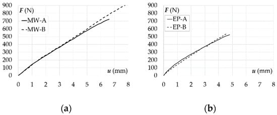
Figure 11.
Load-displacement relations for the pull-out of a blind rivet installed in sandwich panels subjected to axial static and axial quasi-cyclic loads: (a) core made of mineral wool, (b) core made of expanded polystyrene.
In Figure 12, the influence of an eccentric load in relation to an axial load on the mechanical response of a blind rivet pull-out is presented. It can be observed that the blind connection subjected to the eccentric load is stiffer than the blind connection subjected to the axial load. This is due to the partial compression of the facing and the core by the U-shaped adapter, which leads to an increase in the stiffness of the connection.
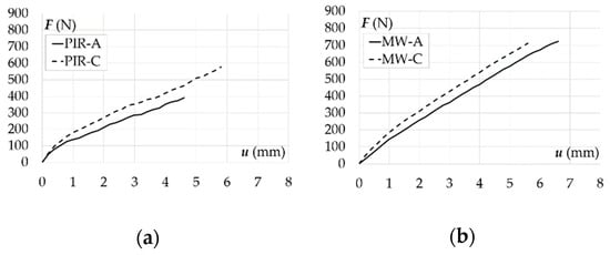
Figure 12.
Load-displacement relations for the pull-out of a blind rivet installed in sandwich panels subjected to static axial and an eccentric loads: (a) core made of PIR foam, (b) core made of mineral wool.
4. Discussion
The conducted research showed that the material of the sandwich panel core layer influences the mechanical response of the blind connection. This structural behavior of blind rivets was defined by four parameters: strength, stiffness, deformation capacity, and failure energy. First, it was observed that the stiffness of the blind connection is the same for sandwich panels with mineral wool and expanded polystyrene cores, while, in the case of the PIR foam core, it is lower. Second, the largest deformation capacity, and therefore the largest failure energy and ultimate strength, were obtained for the mineral wool core layer. Next, the deformation capacity was equal for the polyisocyanurate foam and the expanded polystyrene cores; however, the expanded polystyrene provided a higher ultimate strength and failure energy. Finally, the regularities defined above were insensitive to the nature (static and quasi-cyclic) and the type (axial and eccentric) of loading.
The influence of the load nature was also taken into account. It was revealed that, regardless of the sandwich panel core layer material, the eccentric load increased the stiffness of the blind connection, while the quasi-cyclic load had no negative influence on the mechanical response of the blind connection. This last observation is very promising in the context of civil engineering applications, where the wind load is characterized by variability over time.
The results revealed that the mechanical response of the blind connection could be expressed by means of a linear function and third-degree polynomial for axially and eccentrically loaded test specimens, respectively. The authors’ proposed formulas can be used by practitioners to assess the mechanical response of blind rivets by respecting the calculated characteristic values of the displacements. The analytical formulas provide forces with an error of less than 5%. Moreover, information about the value of the ultimate force and the mechanical response of the blind rivets allows one to possibly consider replacing traditional through-drilling fasteners with blind rivets to fasten light-suspended elements to sandwich panels, e.g., a suspended ceiling, sprinkler system, etc. In contrast to self-drilling fasteners, blind rivets do not require a full penetration of the thermal core layer; therefore, thanks to their use, the number of thermal bridges in a structure could be reduced.
Author Contributions
Conceptualization, R.S.; methodology, R.S.; validation, R.S. and K.C.; investigation, R.S. and K.C.; resources, R.S. and K.C.; writing—original draft, R.S.; writing—review and editing, R.S. and K.C.; visualization, R.S.; supervision, R.S.; project administration, R.S.; funding acquisition, R.S. All authors have read and agreed to the published version of the manuscript.
Funding
This research was funded by Narodowe Centrum Nauki, grant number 2018/02/X/ST8/02657.
Conflicts of Interest
The authors declare no conflict of interest.
References
- Yang, H.; Song, L.; Hu, Y.; Yuen, R.K.K. Diphase flame-retardant effect of ammonium polyphosphate and dimethyl methyl phosphonate on polyisocyanurate-polyurethane foam. Polym. Adv. Technol. 2018, 29, 2917–2925. [Google Scholar] [CrossRef]
- Gnip, I.; Vėjelis, S.; Keršulis, V.; Vaitkus, S. Strength and deformability of mineral wool slabs under short-term compressive, tensile and shear loads. Constr. Build. Mater. 2010, 24, 2124–2134. [Google Scholar] [CrossRef]
- Chen, W.; Hao, H.; Hughes, D.; Shi, Y.; Cui, J.; Li, Z. Static and dynamic mechanical properties of expanded polystyrene. Mater. Des. 2015, 69, 170–180. [Google Scholar] [CrossRef]
- Studziński, R. Experimental investigation of the use of blind rivets in sandwich panels. J. Sandw. Struct. Mater. 2020. [Google Scholar] [CrossRef]
- Polus, Ł.; Szumigała, M. An experimental and numerical study of aluminium–concrete joints and composite beams. Arch. Civ. Mech. Eng. 2019, 19, 375–390. [Google Scholar] [CrossRef]
- Chybiński, M.; Polus, Ł. Theoretical, experimental and numerical study of aluminium-timber composite beams with screwed connections. Constr. Build. Mater. 2019, 226, 317–330. [Google Scholar] [CrossRef]
- Carlsson, L.A.; Kardomateas, G.A. Structural and Failure Mechanics of Sandwich Composites; Springer: Dordrecht, The Netherlands, 2011. [Google Scholar] [CrossRef]
- Zenkert, D. An Introduction to Sandwich Construction; Emas Publishing: Woodmanton Lodge, UK, 1995; ISBN 9780947817770. [Google Scholar]
- Pozorski, Z. Sandwich Panels in Civil Engineering-Theory, Testing and Design; Wydawnictwo Politechniki Poznańskiej: Poznań, Poland, 2016; ISBN 978-83-7775-401-6. [Google Scholar]
- Studziński, R.; Pozorski, Z.; Garstecki, A. Failure maps of sandwich panels with soft core. In Proceedings of the 10th International Conference Modern Building Materials, Structures and Techniques, Vilnius, Lithuania, 19–21 May 2010; Vilnius Gediminas Technical University, Department of Construction Economics & Property: Vilnius, Lithuania, 2010; pp. 1060–1065. [Google Scholar]
- Studziński, R. Optimal design of sandwich panels with hybrid core. J. Sandw. Struct. Mater. 2019, 21, 2181–2193. [Google Scholar] [CrossRef]
- Fang, X.; Chen, J.; Lu, B.; Wang, Y.; Guo, S.; Feng, Z.; Xu, M. Optimized design of sandwich panels for integral thermal protection systems. Struct. Multidiscip. Optim. 2017, 55, 13–23. [Google Scholar] [CrossRef]
- Montemurro, M.; Catapano, A.; Doroszewski, D. A multi-scale approach for the simultaneous shape and material optimisation of sandwich panels with cellular core. Compos. Part B 2016, 91, 458–472. [Google Scholar] [CrossRef]
- Theodosiou, T.G.; Tsikaloudaki, A.G.; Kontoleon, K.J.; Bikas, D.K. Thermal bridging analysis on cladding systems for building facades. Energy Build. 2015, 109, 377–384. [Google Scholar] [CrossRef]
- Sadauskiene, J.; Ramanauskas, J.; Vasylius, A. Impact of point thermal bridges on thermal properties of building envelopes. Therm. Sci. 2020, 24, 2181–2188. [Google Scholar] [CrossRef]
- Lawrence, F.W. Blind fastener for sandwich panel and method. U.S. Patent 3434262, 1967. [Google Scholar]
- Worthing, A.L. Sandwich panel fastener. U.S. Patent 4846612, 1987. [Google Scholar]
- Gauron, R.F. Inset panel fastener and method of using. U.S. Patent 4812193, 1989. [Google Scholar]
- Pratt, J.D. Blind Fastening. Composites, Vol 1. Engineered Materials Handbook; ASM International: Novelty, OH, USA, 1987; pp. 709–711. [Google Scholar]
- Demelio, G.; Pappalettere, C.; Tambone, R. An experimental investigation of the behaviour of sandwich composite structures joined by fasteners. In Proceedings of the BSSM-SEM International Conference, Edinburgh, UK, 30 August–1 September 1994. [Google Scholar]
- Demelio, G.; Genovese, K.; Pappalettere, C. An experimental investigation of static and fatigue behaviour of sandwich composite panels joined by fasteners. Compos. Part B 2001, 32, 299–308. [Google Scholar] [CrossRef]
- Biccari, D.; Genovese, K.; Pappalettere, C. Static and Fatigue Behaviour of Sandwich Composite Panels Joined by Blind Fasteners. Key Eng. Mater. 2001, 221, 61–70. [Google Scholar] [CrossRef]
- Misiek, T.; Käpplein, S. Fastening to face sheets of sandwich panels. ce/Papers 2017, 1, 1746–1755. [Google Scholar] [CrossRef]
- ISO 12491:1997(en) Statistical Methods for Quality Control of Building Materials and Components. Available online: https://www.iso.org/standard/2644.html (accessed on 1 September 2020).
- EN 14509:2013(en) Self-Supporting Double Skin Metal Faced Insulating Panels-Factory Made Products–Specifications. Available online: https://shop.bsigroup.com/en/ProductDetail/?pid=000000000030266551 (accessed on 1 September 2020).


© 2020 by the authors. Licensee MDPI, Basel, Switzerland. This article is an open access article distributed under the terms and conditions of the Creative Commons Attribution (CC BY) license (http://creativecommons.org/licenses/by/4.0/).