Abstract
Functionally graded lattice structures produced by additive manufacturing are promising for bone tissue engineering. Spatial variations in their porosity are reported to vary the stiffness and make it comparable to cortical or trabecular bone. However, the interplay between the mechanical properties and biological response of functionally graded lattices is less clear. Here we show that by designing continuous gradient structures and studying their mechanical and biological properties simultaneously, orthopedic implant design can be improved and guidelines can be established. Our continuous gradient structures were generated by gradually changing the strut diameter of a body centered cubic (BCC) unit cell. This approach enables a smooth transition between unit cell layers and minimizes the effect of stress discontinuity within the scaffold. Scaffolds were fabricated using selective laser melting (SLM) and underwent mechanical and in vitro biological testing. Our results indicate that optimal gradient structures should possess small pores in their core (~900 µm) to increase their mechanical strength whilst large pores (~1100 µm) should be utilized in their outer surface to enhance cell penetration and proliferation. We suggest this approach could be widely used in the design of orthopedic implants to maximize both the mechanical and biological properties of the implant.
1. Introduction
Recent advances in additive manufacturing have revealed new possibilities for the design of the next generation of metallic biomedical implants based on lattice structures. Generally, a bone scaffold should possess four essential characteristics [1,2]: (i) biocompatibility; (ii) mechanical properties matching those of the host tissue; (iii) an interconnected porous structure for cell migration and proliferation and nutrient–waste transportation; (iv) suitable surface characteristics for cell attachment. Traditionally, large bone defects are treated with metallic implants. Several metals have been shown to fulfil the requirement of biocompatibility including cobalt-based alloys, stainless steels as well as titanium alloys [3]. However, metallic implants possess higher elastic moduli than bone, e.g., Ti6Al4V and 316 L stainless steel have a modulus of around 110 GPa and 210 GPa [4] respectively, whereas the modulus of cortical bone is in the range of 3–20 GPa [5]. The mismatch between the modulus of the bone and the implant results in the failure of the implant in the long-term due to the stress-shielding problem [6]. Therefore, matching the mechanical properties of the implant to the host bone and simultaneously providing the implant with biological performance remains a challenge. One potential strategy is to create porous metallic scaffolds where the porosity, the pore size and shape are optimized collectively to reduce the modulus while maintaining the strength of the scaffold [7].
Porous Ti6Al4V scaffolds are ideal candidates as bone scaffolds since they comply with the aforementioned requirements: they are biocompatible [8,9] and their mechanical properties can be adjusted by porosity [10]. Porous structures with an interconnected pore network are of particular interest for promoting cell migration and colonization [11] as well as tissue in-growth [12,13]. Interconnected pore network enables the flow of nutrients and oxygen to cells and tissue and promotes the formation of blood capillaries [14]. When the vascular network is not sufficient, nutrient and oxygen deficiencies cause hypoxia or necrosis [15,16]. Therefore, open-porous structures with adequate pore sizes are critical for vascularization and tissue growth. However, the optimum porous structure for orthopedic scaffolds is yet to be established and there is conflicting information regarding an optimum pore size for both enhanced bone ingrowth and mechanical strength of the scaffold. Recent reviews [17,18,19] summarize that optimum pore size should be 300 µm or larger for bone ingrowth and vascularization. However, whilst high porosity and/or large pore size (>800 µm) promotes flow of nutrients, vascularization and tissue growth [14,15,20], highly porous structures lack the required mechanical strength and integrity and decrease the cell seeding efficiency [15,21]. At the same time, in vitro studies have shown that scaffolds with small pore sizes (<500 µm) or low porosities are prone to pore occlusions [22].
Gradient structures present a potential solution to the opposing requirements of an optimal pore size for biological response and mechanical properties. Given an optimal pore size distribution, there is potential to develop structures that exhibit both adequate mechanical strength and tissue in-growth rate. In addition, gradient structures can mimic the natural bone in terms of its structure and mechanical properties [23]. The structure of the bone changes with the amount and direction of the applied stress [24] resulting in differences in the internal structure (porosity and composition) and mechanical properties of the bone along its dimensions. For example, the elastic modulus of trabecular bone at the ends of long bones or within the interior of vertebrae is around 0.5 GPa [25]. This variation in elastic modulus depending on the location in the bone indicates the need for development of gradient structures in bone scaffolds.
The gradient and uniform porous scaffolds can be designed using traditional CAD (Computer Aided Design) and include the use of open cellular foams [26,27] and periodic uniform unit cells based on platonic solids [28,29,30]. Other techniques, such as implicit surface modelling [31,32,33] and topology optimized scaffolds [18,34], are also gaining in popularity. The fabrication of such complex structures has recently become feasible with the advances in additive manufacturing [35]. Traditional manufacturing of porous metals such as solid or liquid state processing has limited control over the shape and size of the pores achievable through adaptation of the processing parameters. These shortcomings can be overcome through additive manufacturing which builds a three-dimensional object in layer-by-layer fashion. Selective laser melting (SLM) and electron beam melting (EBM) have both been utilized to successfully fabricate porous scaffolds [36]. Both methods rely on a computer-controlled high power energy source to selectively melt a metallic powder on each layer.
A number of studies have investigated the mechanical or biological response of metallic-based gradient porous designs produced by additive manufacturing [37,38,39,40,41,42,43,44,45]. The majority of these studies focused on gradient structures generated by abrupt changes between layers based on change in strut diameter or unit cell volume. For instance, Li et al. [37] studied the deformation behavior of radial dual-density rhombic dodecahedron Ti6Al4V scaffolds fabricated by EBM. They achieved radial dual-density by altering the rhombic dodecahedron unit volume between two layers which resulted in discontinuity between layers. Their finite volume method simulations revealed that the inherent discontinuity between layers resulted in stress concentration and maximum stresses at the interfaces. They concluded that continuous variation between layers are ideal to minimize the stress concentration at the interface. Nune et al. [38,39] investigated the osteoblastic functions of the scaffolds designed using Li et al. [37] work, based on gradient rhombic dodecahedron created by changing the unit volume between layers. Although their work showed promising results on cellular activity when cells were seeded from large pore side (1000 µm), there was no complementary study on the mechanical properties and therefore the adverse effect of discontinuity between layers on the mechanical properties were not covered.
Another study [40] of multiple-layer gradient structures based on changing unit cell volume also showed the mismatch between two layers. They designed gradient BCC and diamond cylinders where two different unit cell volumes were used in the outer and inner parts of the cylinder. This design approach resulted in free nodes of outer layers that are not connected to inner layers, which caused a negative effect on the mechanical properties. Another approach frequently used to generate gradient structures is based on a sharp change in strut diameter between layers [41,42]. This design principle also results in a mismatch between layers negatively effecting the mechanical properties as well as tissue ingrowth and mineralization [42].
Recently, there have been a few investigations aiming to overcome the problem of a mismatch between layers by designing continuous gradient structures which consists of gradually changing strut diameters between layers. For example, Han et al. [43] reported the mechanical properties of SLM-fabricated pure titanium Schwartz diamond unit cell and demonstrated the layer-by-layer sequential failure of these gradient scaffolds. Maskery et al. [44] also showed the layer-by-layer gradual collapse of gradient scaffolds using SLM-fabricated AlSi10Mg gradient BCC structures. These two studies highlighted that the deformation and energy absorption of gradient lattices is more predictable than the uniform lattices due to the lack of diagonal shear band formation during deformation. In another study Ti6Al4V cubic and honeycomb lattice structures [45] were combined to a gradient structure with a continuous density change and it was shown that this design had a superior energy absorption properties compared to their uniform counterparts. Although the aforementioned studies on the mechanical properties of continuous gradient structures indicate promising results; the selection of unit cells, materials as well as their in vitro and in vivo response need to be better understood.
In this work, we introduce a concept of generating continuous gradient structures by changing the strut diameter linearly across cell layers which enables a smooth transition between layers. To demonstrate the benefit of this design principle, we apply it to the BCC unit cell and create gradient structures with rising or decreasing pores sizes. These gradient structures were mirrored from the central horizontal axis to obtain a symmetrical sample. Their mechanical properties were obtained by uniaxial compression tests and cell attachment and proliferation were assessed with murine pre-osteoblast cells. It will be shown that gradient scaffold can be tailored to fulfil the mechanical properties required and simultaneously improve biological response.
2. Materials and Methods
2.1. Design and Fabrication of Ti6Al4V Gradient Cellular Structures
The lattice structures were designed with Rhinoceros v5 in the RhinoPython environment. A custom-made parametric script was developed to create the lattice models with continuous gradient structures. The scaffold structure is defined by its type (BCC) (Figure 1a) and size in each of the cardinal directions, and has a changing strut diameter based upon a polynomial equation, see Equation (1). The diameter of the strut is calculated at a minimum or three locations, evenly spaced along its length based on the location of the strut, and lofted to create a smooth transition between radii.
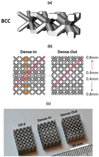
Figure 1.
(a) Gradient BCC unit cell showing continuous transition at the unit cell junctions, (b) CAD view of the gradient BCC lattice scaffold; the arrows show the gradual increase in strut diameter and the highlighted areas show the gradually changing pore size and strut diameter along the scaffolds’ height; Dense-In scaffold has increasing strut diameter towards the center, whereas Dense-Out follows the opposite trend; (c) SLM-fabricated specimens with dimensions of 10 × 10 × 12 mm3, from left to right: uniform BCC lattice scaffold with 0.6 mm strut diameter, Dense-In and Dense-Out scaffolds.
Here c is constant, is the gradient value in the current cardinal direction, is the absolute current coordinate position in the relevant axis (x, y, or z), is the gradient origin in each of the relevant axes, defined over n polynomial terms.
In the case of linear gradient in a single axis, only a single term (Ax) is required, simplifying the Equation (1) to following:
It should be noted that by adding y and z terms in Equation (2) will modify the nature of the gradient and allow to produce 3D gradient scaffolds.
To demonstrate the benefit of this concept, we designed two gradient structures with dimensions of 6 × 10 × 10 mm3, mirrored in the x-axis to create lattices of 12 × 10 × 10 mm3. In this case a gradient value Ax was set to 0.07 (mm/mm) and a constant c equal to 0.4 mm. The choice of the parameters is motivated by manufacturability of the struts and leads to a minimum diameter of 0.4 mm and a maximum of 0.82 mm over the 6-mm lattice. When gradient design was mirrored from the thinner strut plane, it is named as Dense-Out and when mirrored from the thicker strut plane, it is named as Dense-In. For comparison of the mechanical and biological response of gradient structures, we also created three uniform BCC structures which utilize the same strut diameters as present in the gradient structure, namely 0.4, 0.6, 0.8 mm. These uniform BCC structures are denoted U0.4, U0.6 and U0.8, respectively.
It should be noted that the developed script is not limited to the BCC unit cell and a large library of common unit cells was programmed allowing us to generate a smooth gradient between layers and tailor their size and local and total porosity.
The uniform and gradient BCC structures were fabricated by selective laser melting (SLM) process, described in [46], using a MLab Cusing machine (Concept Laser, Lichtenfels, Germany). Ti6Al4V-ELI powder supplied by Falcon Tech Co., Ltd. (Wuxi, China) that satisfies ASTM F136 with diameter range of 15–53 µm was used for laser melting process. The Ti6Al4V samples were fabricated using a laser power of 95 W, scan speed of 600 mm/s with a hatch distance of 0.08 mm, the beam spot size of 50 (−5, +25) µm, with oxygen content less than 0.2% in an argon atmosphere and the layer thickness of 25 µm. The samples were built on top of a solid titanium plate and were removed by using Electrical Discharge Machining (EDM, AgieCharmilles CUT 30P, GF, Losone, Switzerland). All samples were 12 mm in height with a cross-section of 10 × 10 mm2. After the samples were removed from the build plate, they were washed in an ultrasonic bath containing ethanol for 4 h to aid in removing the unmelted particles from the surface of the samples. No further surface modifications or heat treatments were applied to the scaffolds.
2.2. Morphological Analysis
Morphological properties were characterized by three methods: scanning electron microscope (SEM), digital densitometry and gas pycnometry. Pore size and strut diameter were measured using SEM (FEI Nova NanoSEM, Thermo Fisher Scientific, Hillsboro, OR, USA) images. The average of four pore sizes and strut diameters was calculated for each specimen. The volume fraction of the samples was measured by both gas pycnometry and digital densitometry. A digital densitometry (SD-200L, AlfaMirage, Osaka, Japan) adopts the Archimedean principle with liquid displacement. Three specimens of each sample were used to measure the volume fraction. In addition to densitometry measurements, the volume fraction of each sample were measured by a gas pycnometry (AccuPyc 1330, Micromeritics, Norcross, GA, USA) with helium gas in 3 repeats. The pycnometry measures the density of solid materials by employing gas displacement and Boyle’s Law of gas expansion. The volume fraction values measured by gas pycnometry were compared with the values obtained from the CAD designs.
2.3. Measurement of Mechanical Properties
A minimum of five specimens of each uniform and gradient structure were mechanically tested under compression using an Instron 5982 universal testing machine with a 100 kN load cell. Following the standard for compression test for porous and cellular metals (ISO 13314:2011), a constant cross-head velocity of 0.72 mm/min was utilized corresponding to a compression strain rate of . The measurements were recorded after a preload of 50–70 N to avoid the initial settling of the samples between plates. A series of images were captured every 1 s during compression testing to record the deformation response of the samples.
The engineering compressive stress was calculated by normalizing the applied compression load with the initial cross-section area of each sample (10 × 10 mm2) and the engineering strain was calculated by the displacement of the cross-heads. The stress-strain curves of each sample were analyzed and the following mechanical properties were calculated based on the guidelines of the ISO Standard 13314:2011: first maximum compressive strength (σmax) (the first local maximum in the stress-strain curve), 0.2% offset yield stress (σy), the elastic gradient (E(σ20–σ50)) (the gradient of the elastic straight line between stresses of 20 and 50 MPa). The ISO Standard recommends determining the elastic gradient between stresses of 20 and 70 MPa; however, since 70 MPa was higher than the 0.2% yield stress point for some of the samples, 50 MPa was adopted for all samples.
2.4. Cell Viability, Proliferation and Morphology
MC3T3-E1, Subclone 4, preosteoblast cells (ATCC® CRL-2593™, Manassas, VA, USA) were cultured in α-MEM medium (Gibco) supplemented with 10% fetal bovine serum (FBS, Gibco) and 1% antibiotic/antimycotic solution (Gibco) in a humidified incubator at 37 °C, 5% CO2. As-fabricated Ti6Al4V uniform and gradient porous structures were cleaned by successive washes with ethanol and phosphate buffer saline (PBS). Subsequently, specimens with dimensions of 10 × 10 × 12 mm3 were placed in a 24-multiwell plate with 3 repeats and seeded at a density of 1 × 10⁵ cells per specimen. In parallel, positive control wells containing SLM-fabricated solid samples were set up. Before any evaluation, all scaffolds were transferred into a new 24-multiwell plate.
Cell viability was assessed at 4 h, 4 days and 7 days after cell culture using the MTS assay (Cell Titre 96 Aqueous One Solution Cell Proliferation Assay, Promega, Madison, WI, USA). After 2.5 h incubation with MTS reagent, 100 µL of solution from each well were transferred into a 96-multiwell plate and the optical absorbance (OD) was measured at 490 nm with a microplate reader (Thermo Scientific™ Multiskan Spectrophotometer, Vantaa, Finland). The degree of cell attachment and spreading was studied by immunofluorescence staining. Samples were fixed with 4% paraformaldehyde (PFA) for 20 min and stained with ActinRed™ 555 ReadyProbes® Reagent (Molecular Probes™, Gaithersburg, MD, USA) following the manufacturer’s instructions and Hoechst 33342 (10 µg/mL) (Thermo Scientific™, Rockford, IL, USA) for 30 min. After immunostaining, the top and bottom of the specimens were examined by fluorescence microscopy (Nikon Eclipse Ti, Tokyo, Japan).
Cell morphology was characterized by scanning electron microscope (SEM) at 4 h, 4 days and 7 days of cell culture. Cells on the specimens were fixed with 2.5% glutaraldehyde in 0.1 M of sodium cacodylate buffer for 2 h and postfixed in 1% osmium tetroxide for 1.5 h at room temperature. Specimens were dehydrated with a gradient series of ethanol (50%, 70%, 80%, 90%, 95% and 100%) followed by a hexamethyldisilazane (hmds) drying procedure. The specimens were sputter coated with gold and inspected using a FEI Nova NanoSEM.
2.5. Statistical Analysis
Statistical analyses were performed using SPSS Statistics 20.0 (SPSS, Inc., Chicago, IL, USA). Data were presented as mean ± standard deviation (SD). One-way analysis of variation (ANOVA) together with Tukey–Kramer post-hoc analysis were used to identify significant differences (significance threshold: p < 0.05).
3. Results
3.1. Morphology of Porous Scaffolds
The key morphological parameters of the scaffolds, such as pore size and strut diameter, were measured by SEM and presented in Table 1. The measured strut diameters were larger than the original designs for all samples due to the adhesion of the semimolten powder on the surface (Figure 2b). We measured average surface roughness, Ra, using a Mitutoyo Surftest SJ400 and found it to be around 10 µm. This is in agreement with the reported values of surface roughness of SLM printed lattice structures [47]. In addition, volume fraction was quantified using the gas pycnometry and densitometry (Table 1). The volume fraction values were derived directly from the pycnometry and calculated from the densitometry, based on the following equations:

Table 1.
The morphometric parameters of uniform and gradient BCC structures based on CAD designs, gas pycnometry, digital densitometry and SEM.
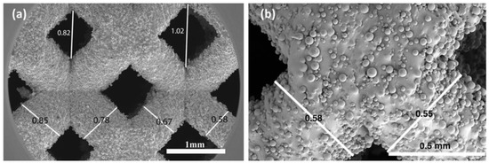
Figure 2.
SEM image of (a) a gradient Dense-Out structure, demonstrating the change in strut diameter and pore size along the scaffold, (b) higher magnification view of the struts showing attached semi-molten powders.
Here, V is the volume of the scaffolds, Wa is the weight measured in air, Ww is the weight measured in water, 0.9971 is the density (g cm−3) of distilled water at 25 °C and 1 atm, Vf is the volume fraction in percent, Vt is the total volume obtained from the outer dimension of the scaffolds, which is 1.2 cm3 for all. The porosity of the scaffolds is defined as 100-Volume fraction (%).
The measured values of volume fraction were smaller than the designed volume fraction values for all samples. The difference between the original designs and pyconometry results was around 13–23%. These deviations are as expected since the as-fabricated strut diameters were larger than the original designs, resulting in smaller pore sizes than the intended geometry. This difference is characteristic to SLM process and is caused by effects such as staircase stepping due to layered manufacturing and melt pool variation due to residual stresses [48].
Strut diameter change along the gradient BCC scaffolds was noticeable in SEM images, (Figure 2a), confirming that the desired graded porosity was successfully achieved by the SLM process. The pore size of gradient Dense-In scaffold was varied from 1.14 mm to 0.74 mm, whereas it was between 0.62 mm to 0.98 mm for gradient Dense-Out scaffold. Measured porosity of the gradient Dense-In and Dense-Out scaffolds were almost identical due to symmetric design along the horizontal center plane.
3.2. Mechanical Properties of Porous Scaffolds
The compressive nominal stress–strain plots of uniform and gradient BCC structures are presented in Figure 3. The stress–strain curves exhibit characteristic stages of deformation for cellular solids [10,49], including linear elastic region, followed by plateau region with fluctuating stresses. The uniform structures showed similar behavior under compression; however, they reached different levels of maximum stress and possess different elastic moduli. The stress–strain curves for gradient structures also showed initially similar behavior to the uniform scaffolds. After the onset of plasticity an abrupt structural collapse was observed in uniform scaffolds, but not in the gradient scaffolds. Furthermore, the fluctuating degree of plateau region was more distinguished for the uniform scaffolds than the gradient scaffolds.
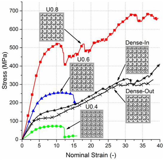
Figure 3.
Nominal stress–strain curves for uniform and gradient structures.
The elastic gradient between stresses of 20 MPa and 50 MPa (E(σ20–σ50)), the 0.2% offset yield stress (σy) and the first maximum compressive strength (σmax) of the scaffolds are summarized (Table 2). Elastic modulus, yield stress and compressive strength increases with extension in strut diameter of the uniform structures or decrease in porosity. Aligned with the expectations of composite rule of mixtures [50], the values of elastic modulus, compressive strength and yield stress of gradient structures lie between those values of the uniform structures. No significant difference between elastic modulus of gradient structures and Uniform 0.6 sample was observed (Supplementary document Figure S1).
Table 2.
The summary of the mechanical properties of uniform and gradient BCC structures measured by compression tests. (Mean ± SD).
Relative modulus (E/E0) against the measured volume fraction (%) is plotted in Figure 4. Elastic modulus was normalized relative to the values of solid Ti6Al4V (110 GPa). The observed average trend shows a positive power relation with the volume fraction and this trend corresponds to theoretically expected behavior of bending-dominated structures [10,51]. Results of a similar study from the literature were used to support our data [52]. The gradient structures were not considered for the power law curve since their volume fraction is similar to U0.6 specimen.
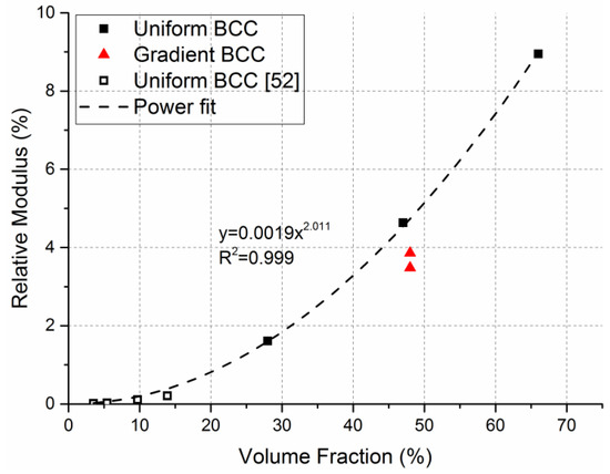
Figure 4.
Relative elastic modulus vs volume fraction (%) of uniform and gradient BCC structures. Power law curve and equation was fitted on the uniform BCC structure data and demonstrates bending-dominated behavior.
Images of the initial stage and the progressive failure of uniform and gradient structures recorded during the compression tests (Figure 5) show that the major failure bands were formed at a 45° angle from the loading direction for all uniform BCC structures. For the gradient structures, the fracture initiated from the thinnest struts, that is at the top and bottom plane for Dense-In and in the middle for Dense-Out. This diagonal shear collapse of uniform structures is typical behavior of BCC structures [52,53,54] and other structures with different cell geometries [55,56] owing to strut bending at lattice joints [51].
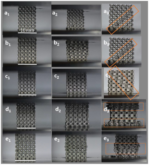
Figure 5.
Failure modes of (a) U0.4, (b) U0.6, (c) U0.8, (d) Dense-In, (e) Dense-Out structures. Left images (subscript 1) represent the initial state and middle (subscript 2) and last right images (subscript 3) present the progressive failure. Highlights represent the observed regions of deformation and failure. (Scale bars = 10 mm).
3.3. Cellular Response to Porous Scaffolds
In order to determine the ability of the scaffolds to interact with cells, the adhesion of MC3T3-E1 preosteoblast cells on the gradient, uniform and solid scaffolds were determined by MTS assay after 4 h of incubation and showed no significant difference in cell seeding between the scaffolds (Figure 6).
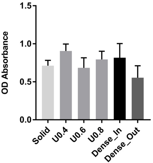
Figure 6.
Adhesion of cells to uniform and gradient porous structures and to solid control sample as measured by MTS assay after 4 h. The optical absorbance (OD) was measured at 490 nm. Data are presented as mean ± SD (n = 3). No statistically significant differences were observed between scaffolds.
In order to determine the extent of cell proliferation on the scaffolds, an MTS assay was performed after 4 and 7 days of culture. The uniform scaffolds showed a trend of decreasing cell number with increasing strut diameter at both days 4 and 7 (Figure 7). For the U0.4 and U0.6 scaffolds the number of cells approximately doubled across this time period whilst there was only a 70% increase on the U0.8 scaffold (Figure 8), further extending the difference in cell number between the samples. For the gradient scaffolds, there were no significant differences in cell number on day 4. However, from day 4 to day 7, there was almost a 400% increase in cell numbers on the Dense-In scaffold but only 20% increase in cell numbers on the Dense-Out scaffold, resulting in significantly fewer cells on the Dense-Out scaffold as compared to the Dense-In scaffold on day 7. Although solid control sample showed the highest cell number at day 7, the percentage increase from day 4 to day 7 was largest for Dense-In scaffold. The final cell number on the Dense-Out scaffold was comparable to that of the U0.8, with both scaffolds having similar diameter of the outermost struts of the design. These results suggest that the scaffolds having thinner struts or larger pores on their outside surface (such as U0.4 and Dense-In) were more favorable for cell proliferation than the scaffolds having thicker struts or smaller pores on their outer surface. Given that the surface area of Dense-In and Dense-Out is identical as a result of their symmetrical design, it can be said that the cell viability was independent of surface area in this study.
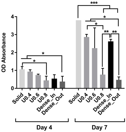
Figure 7.
Cell proliferation measured by MTS assay after culturing 4 and 7 days on the uniform and gradient porous structures. The optical absorbance (OD) was measured at 490 nm. Data were presented as mean ± SD (n = 3). (* p < 0.05, ** p < 0.01, *** p < 0.001 when compared using ANOVA Tukey–Kramer post-hoc test).
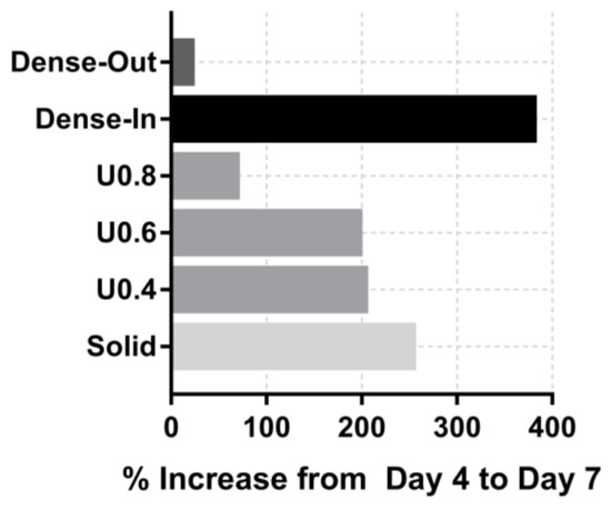
Figure 8.
Percentage increase in od absorbance of the scaffolds from day 4 to day 7.
Further to cell proliferation, cell distribution on the uniform and gradient scaffolds was studied by staining and imaging the cell nuclei and actin cytoskeleton. After 4 h of incubation, all of the scaffolds had similar cell distribution on their top surface (i.e., the surface onto which the cells were seeded) (Figure 9). The lack of cells at the bottom of the scaffolds suggests that most of the initial attachment was on the top surface. After 4 days, substantially more cells were observed both on the top and bottom surfaces of the U0.4 and Dense-In scaffolds, whereas there were no noticeable differences on the other scaffolds between 4 h and day 4 time points (Figure 10). At day 7, all the scaffolds had high density of cells on their top surface; whilst, the bottom surface of U0.6, U0.8 and Dense-Out scaffolds had almost no cells. In contrast, the bottom surface of U0.4 and Dense-In scaffolds had visibly higher cell densities.
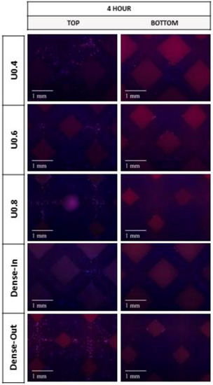
Figure 9.
Fluorescence micrographs representing merged Hoechst stained nucleus (blue) and actin cytoskeleton (red) of MC3T3-E1 preosteoblast cells on the uniform and gradient BCC structures after culturing for 4 h. Top represents the side where cells were seeded onto the samples.
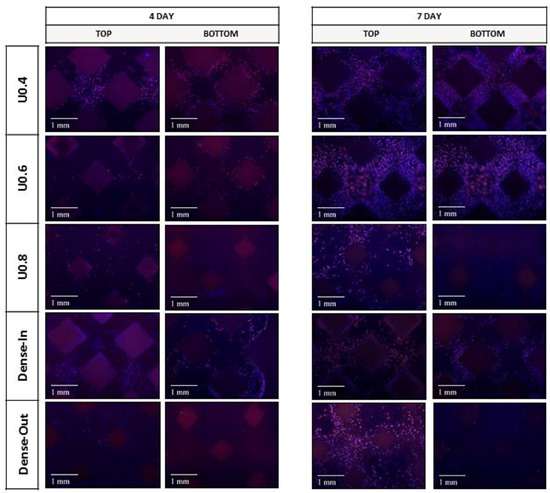
Figure 10.
Fluorescence micrographs representing merged Hoechst stained nucleus (blue) and actin cytoskeleton (red) of MC3T3-E1 preosteoblast cells on the uniform and gradient BCC structures after culturing for 4 days and 7 days. Top represents the side where cells were seeded onto the samples.
Despite the difference in cell proliferation and migration on the different scaffolds, cell morphology was similar for the scaffolds when the images were taken from the top surface (Figure 9). SEM images taken from the middle and bottom part of the scaffolds supported the findings of fluorescent images showing differing cell penetration depth profiles for the varying scaffold structures (Supplementary document Figures S2–S6). The number of cells decreased in the middle and bottom parts of the U0.8 and Dense-Out scaffolds, as compared to U0.4 and Dense-In scaffolds. Cells were noticed to form a sheet-like elongated matrix (dashed line) (Figure 9). Moreover, the morphology of cells presented a high density of filopodia-like projections (red arrows) extending from the leading edges of cells and interacting with the substrate. The interaction between cells and substrate observed by SEM (Figure 11) shows that cells attach both on and between the unmelted powders, indicating that SLM process are beneficial to cell attachment and colonization.
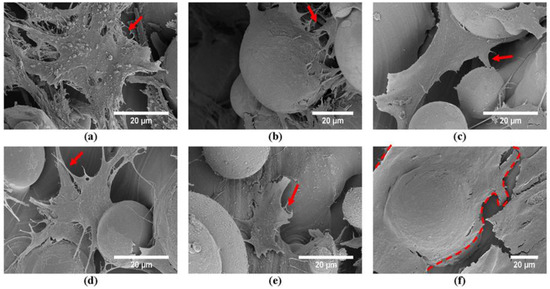
Figure 11.
SEM images of the MC3T3 preosteoblast cells after culturing for 7 days on the top surfaces of (a) U0.4, (b) U0.6, (c) U0.8, (d) Dense-In, (e) Dense-Out, (f) solid scaffolds.
4. Discussion
In this work, the effect of gradient porous structures on both biological response and mechanical behavior is investigated. The generated gradient structures, denoted as Dense-In and Dense-Out, utilize gradual change in diameter and therefore minimize the stress concentration at the lattice junctions. The designed pore sizes changed from 940 µm to 1330 µm for the gradient scaffolds. The deviation of pore size and strut diameter between CAD design and fabricated scaffolds were within an expected range [57] and was attributed to surface irregularities [58]. The deviation for each scaffold was similar, demonstrating the consistency of the SLM fabrication process. Porosities of the uniform scaffolds varied from 32% to 72%, and both gradient structures had a porosity of 50%. SEM images revealed that all scaffolds had unmelted powder attached to the surface of the struts due to layered manufacturing and melt pool variation during the SLM process.
The stiffness of the tested scaffolds varied in the range of 1.6 to 9.0 GPa, which aligns with the stiffness range of the trabecular (0.4 GPa [59,60]) and cortical bones (3–20 GPa [5,24]). The yield stress values of the scaffolds were in the range of 53 to 392 MPa, which lies in the range of cortical bones (33–193 MPa [24,61]), but it is not suitable for a replacement of trabecular bone, 2–17 MPa [60]. Considering the scaffolds presented in this study aim to be used as load-bearing implants for replacement of cortical bones, the yield stress and elastic modulus values satisfy the mechanical property requirements.
Table 2 shows that the elastic modulus, yield stress and maximum compressive strength values increase as the strut diameter increases or porosity decreases. The mechanical properties of gradient structures lie in the range of representative values of uniform structures and can be predicted based on an assumption that gradient structures are composites of uniform layers of the same diameter struts. Based on this assumption, the elastic modulus of gradient structure in uniaxial compression can be calculated through the general rule of mixtures [42,50]:
Using Equation (1), elastic modulus of gradient structure was calculated to be 3.2 GPa, which is comparable to the measured values of 3.9 and 3.5 GPa for Dense-In and Dense-Out scaffolds, respectively.
The deformation response of uniform BCC structures follows the bending-dominated behavior with diagonal shear collapse. Interestingly, the failure mechanism of gradient structures was different due to sequential layer collapse and various deformation stages occurring simultaneously. Thinner struts reached the densification stage (when two opposite cell walls come together as the pore size decreases) while the thicker struts were still in the plateau region during the compression test. The predominant fracture band of gradient structures was initiated at the thinnest struts due to high stress concentrations on the thin strut junctions. This failure mechanism has also been noted in other studies [44,45].
Further to mechanical behavior studies, we analyzed the in vitro response of the scaffolds with preosteoblast cells. The degree of cell attachment was similar for all scaffolds, but cell proliferation and colonization were significantly different. Scaffolds with a thin strut diameter on the periphery (U0.4 and Dense-In) allowed cells to populate throughout the scaffold whereas those with a thicker outer strut (U0.6, U0.8 and Dense-Out) did not allow cells to migrate to the bottom surface, suggesting that cells were entrapped at the smaller pore size region (top surface). Consequently, the proliferation rate of cells on these scaffolds was markedly less. Although this immobilization behavior of the preosteoblast cells when seeded from small pore size region was observed in the previous studies of Nune et al. [38,39], the underlying reason for this behavior is still unknown. The smallest pore size in our scaffolds were 940 µm which is larger than the suggested pore size (100–300 µm) for cell colonization and migration [62,63]. In addition, the smallest pore size is much larger than an average size of a MC3T3-E1 pre-osteoblast cells (20–40 µm, Figure 9). It is not yet clear why thicker struts on the scaffold periphery inhibit cell activity whilst the thick struts on the interior of the Dense-In scaffold did not deter colonization of cells through the whole structure.
Our results suggest that the surface area does not affect the cell attachment and proliferation. The large surface area of the U0.8 scaffold, due to its large strut diameters, was expected to promote cell attachment and growth; however, it showed the lowest cell number at day 7. Similar behavior was observed for the gradient structures, which possessed equal surface area but showed a large difference in cell number. It is therefore likely that, parameters other than the surface area of the scaffold affected the cell colonization. Identification of the specific factors would require further clarification but could include the flow conditions and cellular aggregation [39]. In addition, it would be interesting to assess whether vascularization happens more quickly or easily with larger pores on the periphery than the smaller pores on the periphery.
In recent years, additively manufactured gradient structures for tissue engineering have been studied [37,38,39,41,44,64,65]; however these studies either focused on the mechanical properties or biological response independently. In this work, the biological and mechanical responses were assessed simultaneously allowing us to study the overall impact of the designed geometry of the scaffolds. Our results suggest that when designing a porous gradient structure, both biological and mechanical requirements must be considered concurrently, since their requirements are opposing. The compression test results demonstrate the benefit of utilizing smaller pore size in increasing the stiffness and strength of the porous scaffolds; whereas, the cell proliferation data suggests that scaffolds with larger pore size in their outer surface favors cell proliferation. Therefore, it can be concluded that gradient scaffolds provide a possible solution for overcoming the conflicting requirements of bone tissue implants. Gradient structures with decreasing pore size towards their center can provide the required strength and stiffness, while simultaneously promoting cell colonization throughout the whole scaffold. The Dense-In scaffold fabricated in this study has an elastic modulus of 3.9 GPa which is in the range for those of cortical bone [5]. Furthermore, this scaffold has a varying pore size ranging from 1330 µm on the outside to 940 µm at the core. These values have been previously reported to be favorable for cell colonization as well as bone ingrowth and vascularization [66,67,68].
In summary, an ideal scaffold for bone regeneration should facilitate cell attachment, infiltration and matrix deposition to guide bone formation [69] as well as providing initial mechanical support to the surrounding bone [70]. Porous titanium scaffolds can meet the mechanical strength and bone formation requirements without osseoinductive biomolecules [68]; however, the pore size of the scaffolds needs to be high for bone-ingrowth whereas, as the porosity increases, the mechanical strength and integrity of the structure decreases [71]. Gradient structures represent an ideal candidate to overcome these opposing requirements of high porosity and mechanical strength.
Our study demonstrated the benefit of the gradient scaffold with larger pores in its outer surface in terms of gaining optimum mechanical strength and promoting cell attachment and colonization. In addition, this framework demonstrates that mechanical properties can be tailored through gradient structure design and simultaneously improve the biological response. This approach therefore holds significant promise in the development of orthopedic implants, where the location of the implant and the corresponding loading condition can dictate the implant topology.
5. Conclusions
This work combined and assessed the in vitro behavior and mechanical response of gradient and uniform porous scaffolds for bone tissue engineering. For this purpose, five different BCC structures were fabricated using selective laser melting technology. Static mechanical properties of the gradient structures followed the rule of mixtures and the obtained values are in the range of those corresponding values for uniform structures. The mechanical properties of all studied scaffolds are comparable to the reported mechanical properties of the cortical bone. Quantitative analysis of cell viability showed higher cell colonization and proliferation rates for scaffolds with large pores (1000–1100 µm) in their outer surface after 4 and 7 days of culturing. However, when comparing the mechanical properties of structures with this comparable biological activity, the uniform U0.4 scaffold showed less than half of the respective mechanical properties for the Dense-In scaffold. The combined results of compression tests and in vitro biological analyses indicate that the Dense-In scaffold is an ideal porous structure to balance mechanical and biological performances to meet the requirements of load-bearing implants. Based on the results presented in this work, optimal gradient structures should possess small pores in their core in order to increase their mechanical integrity and strength while large pores should be utilized in their outer surface to avoid pore occlusion. We suggest that this approach could be widely used in the design of orthopedic implants to maximize both the mechanical and biological properties of the implant.
Supplementary Materials
The following are available online at http://www.mdpi.com/2075-4701/8/4/200/s1, Figure S1: Mechanical properties of the scaffolds; Figures S2–S6: Observation of cell morphology and distribution along the scaffolds by SEM.
Acknowledgments
Ezgi Onal would like to acknowledge The Clive and Vera Ramaciotti Centre for Structural Cryo-Electron Microscopy. This project is funded by the ARC Research Hub for Transforming Australia’s Manufacturing Industry through High Value Additive Manufacturing (IH130100008) and Jessica E. Frith is supported by an ARC DECRA (DE130100986).
Author Contributions
E.O. and A.M. conceived and designed the experiments; E.O. performed the experiments; E.O., J.E.F., X.W. and A.M. analyzed the data; M.J. contributed generating Python scripts to design structures; all authors contributed to the writing of the paper.
Conflicts of Interest
The authors declare no conflicts of interest.
References
- Hutmacher, D.W. Scaffolds in tissue engineering bone and cartilage. Biomaterials 2000, 21, 2529–2543. [Google Scholar] [CrossRef]
- Hutmacher, D.W.; Schantz, J.T.; Lam, C.X.F.; Tan, K.C.; Lim, T.C. State of the art and future directions of scaffold-based bone engineering from a biomaterials perspective. J. Tissue Eng. Regener. Med. 2007, 1, 245–260. [Google Scholar] [CrossRef] [PubMed]
- Niinomi, M.; Nakai, M.; Hieda, J. Development of new metallic alloys for biomedical applications. Acta Biomater. 2012, 8, 3888–3903. [Google Scholar] [CrossRef] [PubMed]
- Andani, M.T.; Shayesteh Moghaddam, N.; Haberland, C.; Dean, D.; Miller, M.J.; Elahinia, M. Metals for bone implants. Part 1. Powder metallurgy and implant rendering. Acta Biomater. 2014, 10, 4058–4070. [Google Scholar] [CrossRef] [PubMed]
- Bayraktar, H.H.; Morgan, E.F.; Niebur, G.L.; Morris, G.E.; Wong, E.K.; Keaveny, T.M. Comparison of the elastic and yield properties of human femoral trabecular and cortical bone tissue. J. Biomech. 2004, 37, 27–35. [Google Scholar] [CrossRef]
- Moghaddam, N.S.; Andani, M.T.; Amerinatanzi, A.; Haberland, C.; Huff, S.; Miller, M.; Elahinia, M.; Dean, D. Metals for bone implants: Safety, design, and efficacy. Biomanuf. Rev. 2016, 1, 1. [Google Scholar] [CrossRef]
- Al-Tamimi, A.A.; Fernandes, P.R.A.; Peach, C.; Cooper, G.; Diver, C.; Bartolo, P.J. Metallic bone fixation implants: A novel design approach for reducing the stress shielding phenomenon. Virtual Phys. Prototyp. 2017, 12, 141–151. [Google Scholar] [CrossRef]
- Long, M.; Rack, H.J. Titanium alloys in total joint replacement—A materials science perspective. Biomaterials 1998, 19, 1621–1639. [Google Scholar] [CrossRef]
- Abdel-Hady Gepreel, M.; Niinomi, M. Biocompatibility of Ti-alloys for long-term implantation. J. Mech. Behav. Biomed. Mater. 2013, 20, 407–415. [Google Scholar] [CrossRef] [PubMed]
- Ashby, M.F. The properties of foams and lattices. Philos. Trans. R. Soc. A Math. Phys. Eng. Sci. 2006, 364, 15–30. [Google Scholar] [CrossRef] [PubMed]
- Alvarez, K.; Nakajima, H. Metallic scaffolds for bone regeneration. Materials 2009, 2, 790. [Google Scholar] [CrossRef]
- Heinl, P.; Müller, L.; Körner, C.; Singer, R.F.; Müller, F.A. Cellular Ti–6Al–4V structures with interconnected macro porosity for bone implants fabricated by selective electron beam melting. Acta Biomater. 2008, 4, 1536–1544. [Google Scholar] [CrossRef] [PubMed]
- Marin, E.; Fusi, S.; Pressacco, M.; Paussa, L.; Fedrizzi, L. Characterization of cellular solids in Ti6Al4V for orthopedic implant applications: Trabecular titanium. J. Mech. Behav. Biomed. Mater. 2010, 3, 373–381. [Google Scholar] [CrossRef] [PubMed]
- Rouwkema, J.; Rivron, N.C.; van Blitterswijk, C.A. Vascularization in tissue engineering. Trends Biotechnol. 2008, 26, 434–441. [Google Scholar] [CrossRef] [PubMed]
- Kumar, A.; Nune, K.C.; Murr, L.E.; Misra, R.D.K. Biocompatibility and mechanical behaviour of three-dimensional scaffolds for biomedical devices: Process–structure–property paradigm. Int. Mater. Rev. 2016, 61, 20–45. [Google Scholar] [CrossRef]
- Bramfeld, H.; Sabra, G.; Centis, V.; Vermette, P. Scaffold vascularization: A challenge for three-dimensional tissue engineering. Curr. Med. Chem. 2010, 17, 3944–3967. [Google Scholar] [CrossRef]
- Perez, R.A.; Mestres, G. Role of pore size and morphology in musculo-skeletal tissue regeneration. Mater. Sci. Eng. C 2016, 61, 922–939. [Google Scholar] [CrossRef] [PubMed]
- Wang, X.; Xu, S.; Zhou, S.; Xu, W.; Leary, M.; Choong, P.; Qian, M.; Brandt, M.; Xie, Y.M. Topological design and additive manufacturing of porous metals for bone scaffolds and orthopedic implants: A review. Biomaterials 2016, 83, 127–141. [Google Scholar] [CrossRef] [PubMed]
- Sing, S.L.; An, J.; Yeong, W.Y.; Wiria, F.E. Laser and electron-beam powder-bed additive manufacturing of metallic implants: A review on processes, materials and designs. J. Orthop. Res. 2016, 34, 369–385. [Google Scholar] [CrossRef] [PubMed]
- Li, J.P.; Habibovic, P.; van den Doel, M.; Wilson, C.E.; de Wijn, J.R.; van Blitterswijk, C.A.; de Groot, K. Bone ingrowth in porous titanium implants produced by 3D fiber deposition. Biomaterials 2007, 28, 2810–2820. [Google Scholar] [CrossRef] [PubMed]
- Warnke, P.H.; Douglas, T.; Wollny, P.; Sherry, E.; Steiner, M.; Galonska, S.; Becker, S.T.; Springer, I.N.; Wiltfang, J.; Sivananthan, S. Rapid prototyping: Porous titanium alloy scaffolds produced by selective laser melting for bone tissue engineering. Tissue Eng. Part C Methods 2008, 15, 115–124. [Google Scholar] [CrossRef] [PubMed]
- Van Bael, S.; Chai, Y.C.; Truscello, S.; Moesen, M.; Kerckhofs, G.; Van Oosterwyck, H.; Kruth, J.P.; Schrooten, J. The effect of pore geometry on the in vitro biological behavior of human periosteum-derived cells seeded on selective laser-melted Ti6Al4V bone scaffolds. Acta Biomater. 2012, 8, 2824–2834. [Google Scholar] [CrossRef] [PubMed]
- Leong, K.F.; Chua, C.K.; Sudarmadji, N.; Yeong, W.Y. Engineering functionally graded tissue engineering scaffolds. J. Mech. Behav. Biomed. Mater. 2008, 1, 140–152. [Google Scholar] [CrossRef] [PubMed]
- Karageorgiou, V.; Kaplan, D. Porosity of 3D biomaterial scaffolds and osteogenesis. Biomaterials 2005, 26, 5474–5491. [Google Scholar] [CrossRef] [PubMed]
- Li, G.; Wang, L.; Pan, W.; Yang, F.; Jiang, W.; Wu, X.; Kong, X.; Dai, K.; Hao, Y. In vitro and in vivo study of additive manufactured porous Ti6Al4V scaffolds for repairing bone defects. Sci. Rep. 2016, 6, 34072. [Google Scholar] [CrossRef] [PubMed]
- Murr, L.E.; Gaytan, S.M.; Medina, F.; Martinez, E.; Martinez, J.L.; Hernandez, D.H.; Machado, B.I.; Ramirez, D.A.; Wicker, R.B. Characterization of Ti–6Al–4V open cellular foams fabricated by additive manufacturing using electron beam melting. Mater. Sci. Eng. A 2010, 527, 1861–1868. [Google Scholar] [CrossRef]
- Murr, L.E.; Gaytan, S.M.; Medina, F.; Lopez, H.; Martinez, E.; Machado, B.I.; Hernandez, D.H.; Martinez, L.; Lopez, M.I.; Wicker, R.B.; et al. Next-generation biomedical implants using additive manufacturing of complex, cellular and functional mesh arrays. Philos. Trans. R. Soc. Lond. A Math. Phys. Eng. Sci. 2010, 368, 1999–2032. [Google Scholar] [CrossRef] [PubMed]
- Arabnejad, S.; Burnett Johnston, R.; Pura, J.A.; Singh, B.; Tanzer, M.; Pasini, D. High-strength porous biomaterials for bone replacement: A strategy to assess the interplay between cell morphology, mechanical properties, bone ingrowth and manufacturing constraints. Acta Biomater. 2016, 30, 345–356. [Google Scholar] [CrossRef] [PubMed]
- Wettergreen, M.A.; Bucklen, B.S.; Starly, B.; Yuksel, E.; Sun, W.; Liebschner, M.A.K. Creation of a unit block library of architectures for use in assembled scaffold engineering. Comput.-Aided Des. 2005, 37, 1141–1149. [Google Scholar] [CrossRef]
- Parthasarathy, J.; Starly, B.; Raman, S. A design for the additive manufacture of functionally graded porous structures with tailored mechanical properties for biomedical applications. J. Manuf. Process. 2011, 13, 160–170. [Google Scholar] [CrossRef]
- Bobbert, F.S.L.; Lietaert, K.; Eftekhari, A.A.; Pouran, B.; Ahmadi, S.M.; Weinans, H.; Zadpoor, A.A. Additively manufactured metallic porous biomaterials based on minimal surfaces: A unique combination of topological, mechanical, and mass transport properties. Acta Biomater. 2017, 53, 572–584. [Google Scholar] [CrossRef] [PubMed]
- Giannitelli, S.M.; Accoto, D.; Trombetta, M.; Rainer, A. Current trends in the design of scaffolds for computer-aided tissue engineering. Acta Biomater. 2014, 10, 580–594. [Google Scholar] [CrossRef] [PubMed]
- Kapfer, S.C.; Hyde, S.T.; Mecke, K.; Arns, C.H.; Schröder-Turk, G.E. Minimal surface scaffold designs for tissue engineering. Biomaterials 2011, 32, 6875–6882. [Google Scholar] [CrossRef] [PubMed]
- Zhang, X.-Y.; Fang, G.; Zhou, J. Additively manufactured scaffolds for bone tissue engineering and the prediction of their mechanical behavior: A review. Materials 2017, 10, 50. [Google Scholar] [CrossRef] [PubMed]
- Horn, T.J.; Harrysson, O.L.A. Overview of current additive manufacturing technologies and selected applications. Sci. Prog. 2012, 95, 255–282. [Google Scholar] [CrossRef] [PubMed]
- Sidambe, A. Biocompatibility of advanced manufactured titanium implants—A review. Materials 2014, 7, 8168–8188. [Google Scholar] [CrossRef] [PubMed]
- Li, S.; Zhao, S.; Hou, W.; Teng, C.; Hao, Y.; Li, Y.; Yang, R.; Misra, R.D.K. Functionally graded Ti-6Al-4V meshes with high strength and energy absorption. Adv. Eng. Mater. 2016, 18, 34–38. [Google Scholar] [CrossRef]
- Nune, K.; Kumar, A.; Misra, R.; Li, S.; Hao, Y.; Yang, R. Osteoblast functions in functionally graded Ti-6Al-4V mesh structures. J. Biomater. Appl. 2016, 30, 1182–1204. [Google Scholar] [CrossRef] [PubMed]
- Nune, K.C.; Kumar, A.; Misra, R.D.K.; Li, S.J.; Hao, Y.L.; Yang, R. Functional response of osteoblasts in functionally gradient titanium alloy mesh arrays processed by 3D additive manufacturing. Colloids Surf. B Biointerfaces 2017, 150, 78–88. [Google Scholar] [CrossRef] [PubMed]
- Surmeneva, M.A.; Surmenev, R.A.; Chudinova, E.A.; Koptioug, A.; Tkachev, M.S.; Gorodzha, S.N.; Rännar, L.-E. Fabrication of multiple-layered gradient cellular metal scaffold via electron beam melting for segmental bone reconstruction. Mater. Des. 2017, 133, 195–204. [Google Scholar] [CrossRef]
- Limmahakhun, S.; Oloyede, A.; Sitthiseripratip, K.; Xiao, Y.; Yan, C. Stiffness and strength tailoring of cobalt chromium graded cellular structures for stress-shielding reduction. Mater. Des. 2017, 114, 633–641. [Google Scholar] [CrossRef]
- Van Grunsven, W.; Hernandez-Nava, E.; Reilly, G.; Goodall, R. Fabrication and mechanical characterisation of titanium lattices with graded porosity. Metals 2014, 4, 401–409. [Google Scholar] [CrossRef]
- Han, C.; Li, Y.; Wang, Q.; Wen, S.; Wei, Q.; Yan, C.; Hao, L.; Liu, J.; Shi, Y. Continuous functionally graded porous titanium scaffolds manufactured by selective laser melting for bone implants. J. Mech. Behav. Biomed. Mater. 2018, 80, 119–127. [Google Scholar] [CrossRef] [PubMed]
- Maskery, I.; Aboulkhair, N.T.; Aremu, A.O.; Tuck, C.J.; Ashcroft, I.A.; Wildman, R.D.; Hague, R.J.M. A mechanical property evaluation of graded density Al-Si10-Mg lattice structures manufactured by selective laser melting. Mater. Sci. Eng. A 2016, 670, 264–274. [Google Scholar] [CrossRef]
- Choy, S.Y.; Sun, C.-N.; Leong, K.F.; Wei, J. Compressive properties of functionally graded lattice structures manufactured by selective laser melting. Mater. Des. 2017, 131, 112–120. [Google Scholar] [CrossRef]
- Yap, C.Y.; Chua, C.K.; Dong, Z.L.; Liu, Z.H.; Zhang, D.Q.; Loh, L.E.; Sing, S.L. Review of selective laser melting: Materials and applications. Appl. Phys. Rev. 2015, 2, 041101. [Google Scholar] [CrossRef]
- Pyka, G.; Kerckhofs, G.; Papantoniou, I.; Speirs, M.; Schrooten, J.; Wevers, M. Surface Roughness and Morphology Customization of Additive Manufactured Open Porous Ti6Al4V Structures. Materials 2013, 6, 4737–4757. [Google Scholar] [CrossRef] [PubMed]
- Wang, D.; Yang, Y.; Liu, R.; Xiao, D.; Sun, J. Study on the designing rules and processability of porous structure based on selective laser melting (SLM). J. Mater. Process. Technol. 2013, 213, 1734–1742. [Google Scholar] [CrossRef]
- Rashed, M.G.; Ashraf, M.; Mines, R.A.W.; Hazell, P.J. Metallic microlattice materials: A current state of the art on manufacturing, mechanical properties and applications. Mater. Des. 2016, 95, 518–533. [Google Scholar] [CrossRef]
- Nemat-Nasser, S.; Hori, M. Micromechanics: Overall Properties of Heterogeneous Materials, 2nd ed.; Elsevier: Amsterdam, The Netherlands, 1998. [Google Scholar]
- Mazur, M.; Leary, M.; Sun, S.; Vcelka, M.; Shidid, D.; Brandt, M. Deformation and failure behaviour of Ti-6Al-4V lattice structures manufactured by selective laser melting (SLM). Int. J. Adv. Manuf. Technol. 2016, 84, 1391–1411. [Google Scholar] [CrossRef]
- Smith, M..; Guan, Z.; Cantwell, W.J. Finite element modelling of the compressive response of lattice structures manufactured using the selective laser melting technique. Int. J. Mech. Sci. 2013, 67, 28–41. [Google Scholar] [CrossRef]
- Gorny, B.; Niendorf, T.; Lackmann, J.; Thoene, M.; Troester, T.; Maier, H.J. In situ characterization of the deformation and failure behavior of non-stochastic porous structures processed by selective laser melting. Mater. Sci. Eng. A 2011, 528, 7962–7967. [Google Scholar] [CrossRef]
- Cansizoglu, O.; Harrysson, O.; Cormier, D.; West, H.; Mahale, T. Properties of Ti–6Al–4V non-stochastic lattice structures fabricated via electron beam melting. Mater. Sci. Eng. A 2008, 492, 468–474. [Google Scholar] [CrossRef]
- Zhao, S.; Li, S.J.; Hou, W.T.; Hao, Y.L.; Yang, R.; Misra, R.D.K. The influence of cell morphology on the compressive fatigue behavior of Ti-6Al-4V meshes fabricated by electron beam melting. J. Mech. Behav. Biomed. Mater. 2016, 59, 251–264. [Google Scholar] [CrossRef] [PubMed]
- Li, S.J.; Xu, Q.S.; Wang, Z.; Hou, W.T.; Hao, Y.L.; Yang, R.; Murr, L.E. Influence of cell shape on mechanical properties of Ti–6Al–4V meshes fabricated by electron beam melting method. Acta Biomater. 2014, 10, 4537–4547. [Google Scholar] [CrossRef] [PubMed]
- Van Bael, S.; Kerckhofs, G.; Moesen, M.; Pyka, G.; Schrooten, J.; Kruth, J.P. Micro-CT-based improvement of geometrical and mechanical controllability of selective laser melted Ti6Al4V porous structures. Mater. Sci. Eng. A 2011, 528, 7423–7431. [Google Scholar] [CrossRef]
- Parthasarathy, J.; Starly, B.; Raman, S.; Christensen, A. Mechanical evaluation of porous titanium (Ti6Al4V) structures with electron beam melting (EBM). J. Mech. Behav. Biomed. Mater. 2010, 3, 249–259. [Google Scholar] [CrossRef] [PubMed]
- Linde, F.; Hvid, I. The effect of constraint on the mechanical behaviour of trabecular bone specimens. J. Biomech. 1989, 22, 485–490. [Google Scholar] [CrossRef]
- Morgan, E.F.; Keaveny, T.M. Dependence of yield strain of human trabecular bone on anatomic site. J. Biomech. 2001, 34, 569–577. [Google Scholar] [CrossRef]
- Cullinane, D.M.; Einhorn, T.A. Biomechanics of bone. In Principles of Bone Biology, 2nd ed.; Raisz, L.G., Rodan, G.A., Eds.; Academic Press: San Diego, CA, USA, 2002. [Google Scholar]
- Murphy, C.M.; Haugh, M.G.; O’Brien, F.J. The effect of mean pore size on cell attachment, proliferation and migration in collagen–glycosaminoglycan scaffolds for bone tissue engineering. Biomaterials 2010, 31, 461–466. [Google Scholar] [CrossRef] [PubMed]
- Simske, S.J.; Ayers, R.A.; Bateman, T.A. Porous materials for bone engineering. Mater. Sci. Forum 1997, 250, 151–182. [Google Scholar] [CrossRef]
- Dumas, M.; Terriault, P.; Brailovski, V. Modelling and characterization of a porosity graded lattice structure for additively manufactured biomaterials. Mater. Des. 2017, 121, 383–392. [Google Scholar] [CrossRef]
- Sudarmadji, N.; Tan, J.Y.; Leong, K.F.; Chua, C.K.; Loh, Y.T. Investigation of the mechanical properties and porosity relationships in selective laser-sintered polyhedral for functionally graded scaffolds. Acta Biomater. 2011, 7, 530–537. [Google Scholar] [CrossRef] [PubMed]
- De Wild, M.; Zimmermann, S.; Rüegg, J.; Schumacher, R.; Fleischmann, T.; Ghayor, C.; Weber, F.E. Influence of microarchitecture on osteoconduction and mechanics of porous titanium scaffolds generated by selective laser melting. 3D Print. Addit. Manuf. 2016, 3, 142–151. [Google Scholar] [CrossRef]
- Taniguchi, N.; Fujibayashi, S.; Takemoto, M.; Sasaki, K.; Otsuki, B.; Nakamura, T.; Matsushita, T.; Kokubo, T.; Matsuda, S. Effect of pore size on bone ingrowth into porous titanium implants fabricated by additive manufacturing: An in vivo experiment. Mater. Sci. Eng. C 2016, 59, 690–701. [Google Scholar] [CrossRef] [PubMed]
- Fukuda, A.; Takemoto, M.; Saito, T.; Fujibayashi, S.; Neo, M.; Pattanayak, D.K.; Matsushita, T.; Sasaki, K.; Nishida, N.; Kokubo, T.; et al. Osteoinduction of porous Ti implants with a channel structure fabricated by selective laser melting. Acta Biomater. 2011, 7, 2327–2336. [Google Scholar] [CrossRef] [PubMed]
- Khan, W.S.; Rayan, F.; Dhinsa, B.S.; Marsh, D. An osteoconductive, osteoinductive, and osteogenic tissue-engineered product for trauma and orthopedic surgery: How far are we? Stem Cells Int. 2012, 2012, 236231. [Google Scholar] [CrossRef] [PubMed]
- Van der Stok, J.; Van der Jagt, O.P.; Amin Yavari, S.; De Haas, M.F.P.; Waarsing, J.H.; Jahr, H.; Van Lieshout, E.M.M.; Patka, P.; Verhaar, J.A.N.; Zadpoor, A.A.; et al. Selective laser melting-produced porous titanium scaffolds regenerate bone in critical size cortical bone defects. J. Orthop. Res. 2013, 31, 792–799. [Google Scholar] [CrossRef] [PubMed]
- Hollister, S.J. Porous scaffold design for tissue engineering. Nat. Mater. 2006, 5, 590. [Google Scholar] [CrossRef]
© 2018 by the authors. Licensee MDPI, Basel, Switzerland. This article is an open access article distributed under the terms and conditions of the Creative Commons Attribution (CC BY) license (http://creativecommons.org/licenses/by/4.0/).