Article

Effects of Grain Boundary Microconstituents on Heat-Affected Zone Cracks in a Mar-M004 Weldment

1
Department of Materials Science and Engineering, National Taiwan University, Taipei 10617, Taiwan
2
Nuclear Fuels and Materials Division, Institute of Nuclear Energy Research, Taoyuan 32546, Taiwan
3
Institute of Materials Engineering, National Taiwan Ocean University, Keelung 20224, Taiwan
*
Author to whom correspondence should be addressed.
Metals 2018, 8(4), 201; https://doi.org/10.3390/met8040201
Submission received: 26 February 2018 / Revised: 19 March 2018 / Accepted: 19 March 2018 / Published: 21 March 2018

Abstract

:
Repair-welding of a cast Mar-M004 superalloy by gas tungsten arc welding was performed. Liquation cracks of the heat-affected zone (HAZ) in a Mar-M004 weldment were closely related to the presence of low-melting constituents along the solidified boundaries in the weld. The metal carbides (MC), M3B2 and M5B3 borides, Ni7(Hf,Zr)2 intermetallic compounds, and γ-γ′colonies were found at the interdendritic boundaries. Fine boride precipitates mixed with intermetallic compounds in lamellar form were more likely to liquate during repair-welding. The melting of borides and intermetallic compounds in 1180 °C/4 h treated samples confirmed the poor weldability of the Mar-M004 superalloy due to enhanced liquation cracking. In addition to boride formation, fractographs of liquation cracks revealed strong segregation of B element in carbides and intermetallics, which might further lower the solidus temperature of the repair weld.

1. Introduction

Commercial Ni-based superalloys have been extensively applied in extreme environments at elevated temperatures, such as rotors, blades, and critical components in aircraft engines and land-based power plants. These superalloys possess high-temperature strength, excellent oxidation/corrosion resistance, and optimal thermal properties. Precipitation-hardened Ni-based alloys are strengthened through a high-volume fraction of fine γ′ particles [1,2,3,4,5]. The stable creep strength of the Mar-M004 (Hf-modified cast IN713) superalloy during long-term applications at an elevated temperature are the result of the Ni3(Al,Ti)-γ′ precipitates [6]. Microsegregation and non-equilibrium solidification assist the formation of complex solidification products, including primary the metal carbides (MC) carbides, MC/γ eutectics, γ-γ′ eutectic, M5B3 borides, and σ and η phases at the interdendritic boundaries in the cast Ni-based superalloys [7,8,9,10,11,12]. To lower the costs associated with component replacement in land- and air-based gas turbine engines, repair-welding of aeronautic components made of Ni-based superalloys to extend their service lifetime has become increasingly prevalent. In general, the welding/repair-welding of Ni-based superalloys is successfully carried out by electrical arc [13,14], laser beam [15,16,17], electron beam [18], laser powder deposition [19,20], and diffusion bonding [21].
The weldability of precipitation-hardened Ni-based superalloys is known to be very poor, especially for those alloys with high equivalent contents of Al and Ti [22]. Liquidation cracks in the heat-affected zone (HAZ) are the major concern during welding/repair-welding of such superalloys [23]. Semi-coherent interfaces between γ′-γ and negative lattice misfit cause fracture in the HAZ of an IN 713C weld [24]. Constitutional liquation of primary strengthening γ′ precipitates with a high-volume fraction contributes significantly to grain boundary liquation [13]. Furthermore, HAZ liquation in Ni-based superalloys is attributed to the early stage melting of Cr-Mo borides, MC carbides, γ-γ′ eutectics, and Ni-Zr intermetallic compounds along dendritic boundaries [25,26,27]. Additionally, γ-M6C or γ-M23C6 eutectics in lamellar form are also seen in the HAZ of Ni-based superalloy welds [28,29]. To reduce the cracking susceptibility of precipitation-hardened Ni-based superalloys, proper welding parameters and/or the selection of suitable fillers are suggested. With preheating at 300 °C and optimal welding variables, cracking of the IN 792 DS superalloy can be avoided during electron beam welding [18]. Increasing the preheat temperature causes a significant decrease in total crack length in IN738LC fabricated by the laser solid forming process [30]. Preheating IN738LC at a sufficiently high temperature can prevent the weld from cracking [31]. For IN 738LC gas-tungsten arc welds, decreasing the amounts of Al and Ti in fillers can ameliorate the crack susceptibility of the weld [32].
The cast Mar-M004 substrate was repaired by tungsten-inert gas (TIG) arc welding. Causes of the HAZ liquation cracking in the weld were investigated. Microstructures were unveiled with the aid of a field emission scanning electron microscope (FESEM). An electron backscatter diffraction (EBSD) detector was used to perform structural analyses of microconstituents along grain boundaries. The effects of microstructural features on the hot cracking sensitivity of the cast Mar-M004 superalloy were evaluated in the experiment.

2. Materials and Experimental Procedures

Figure 1a shows the macro-view of the vacuum-casted Mar-M004 turbine. The Mar-M004 test plate was wire-cut from the central portion of the cast turbine as illustrated in Figure 1b. Table 1 displays the chemical composition of Mar-M004 in wt. %. Stress relief heat treatment at 1050 °C for 5 h was applied to the Mar-M004 turbine in a vacuum of 5 × 10⁻³ Pa before wire cutting. The size of the specimen used in the repair-welding test was about 60 L × 35 W × 6 T in mm. Several blind holes were machined on the specimen. Figure 1c shows the joint geometry; each blind hole has a bevel angle of 90°, a depth of 1.5 mm, and a root of 2 mm at bottom of the hole to simulate the repair-welding of both surface and sub-surface defects in the Mar-M004 turbine. IN625 wire was used as the filler for TIG arc welding, and the macro-view of the repair weld is shown in Figure 1d. Cross sections of the weld were made either perpendicular or parallel to the top weld surface after repair-welding. A standard metallographic procedure to inspect microcracks in the HAZ and the fusion zone (FZ) of the weld was carried out.
Micro-hardness measurements in various regions of the weldment were performed by using an MVK-G1500 Vickers hardness tester (Mitutoyo, Kawasaki, Kanagawa, Japan) with a load of 300 gf and a duration time of 10 s. At least five measurements at different sites were made, which were located at a specific depth away from the weld interface. Microstructural evolution in the FZ, HAZ, and base metal (BM) was examined by JSM-7100F SEM (JEOL, Tokyo, Japan). Quantitative chemical analyses of different phases/structures in the samples were made either with an X-MaxN energy dispersive spectrometer (EDS, Oxford Instruments, Abingdon, UK) or a JXA-8200 electron probe micro-analyzer (EPMA, JEOL Ltd., Tokyo, Japan). Fracture features of selected samples with cracks were examined using an SEM. Crystallographic analyses of grain boundary microconstituents were analyzed using the NordlysMax2 EBSD detector (Oxford Instruments, Abingdon, UK) attached to an SEM.

3. Results and Discussion

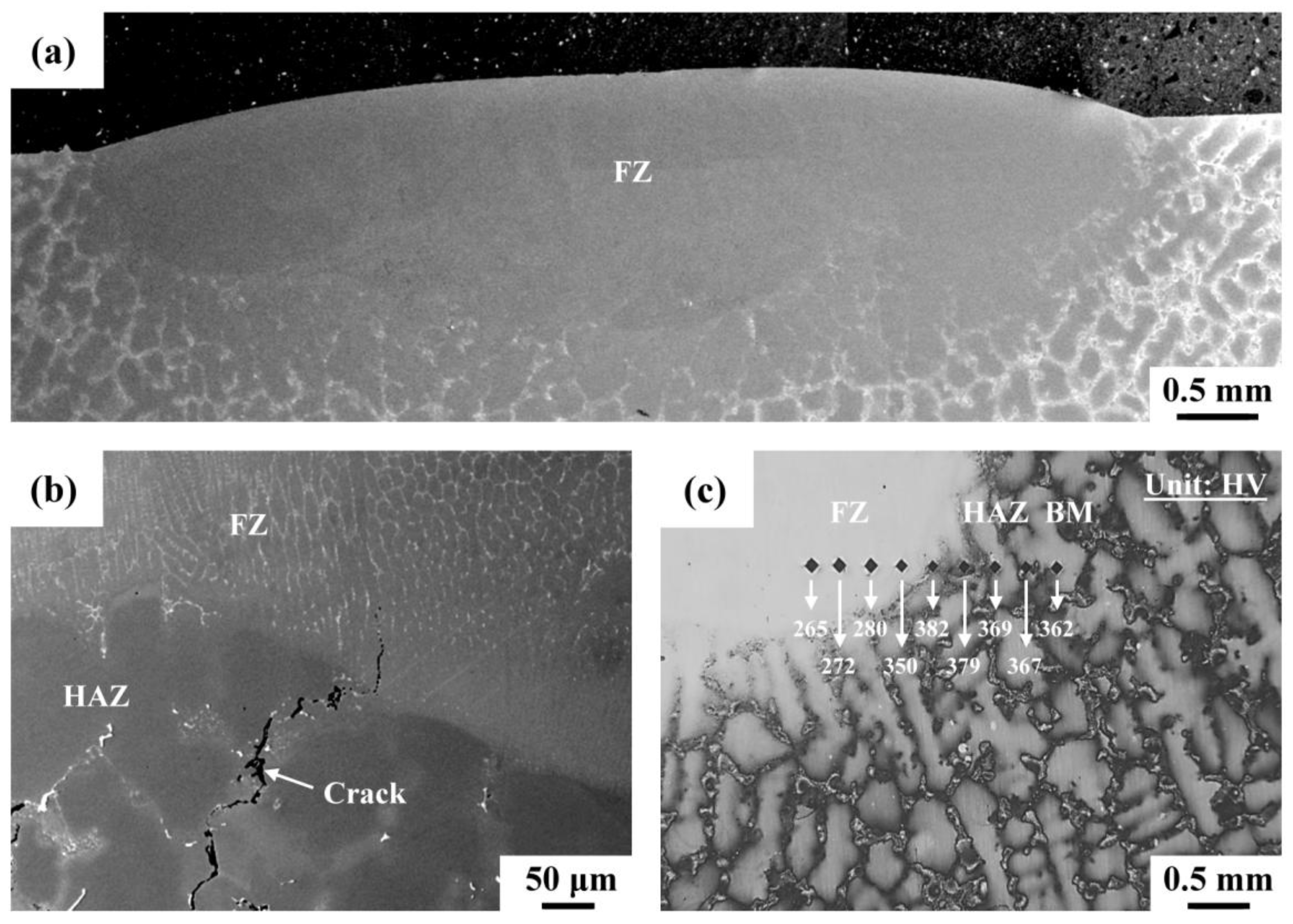
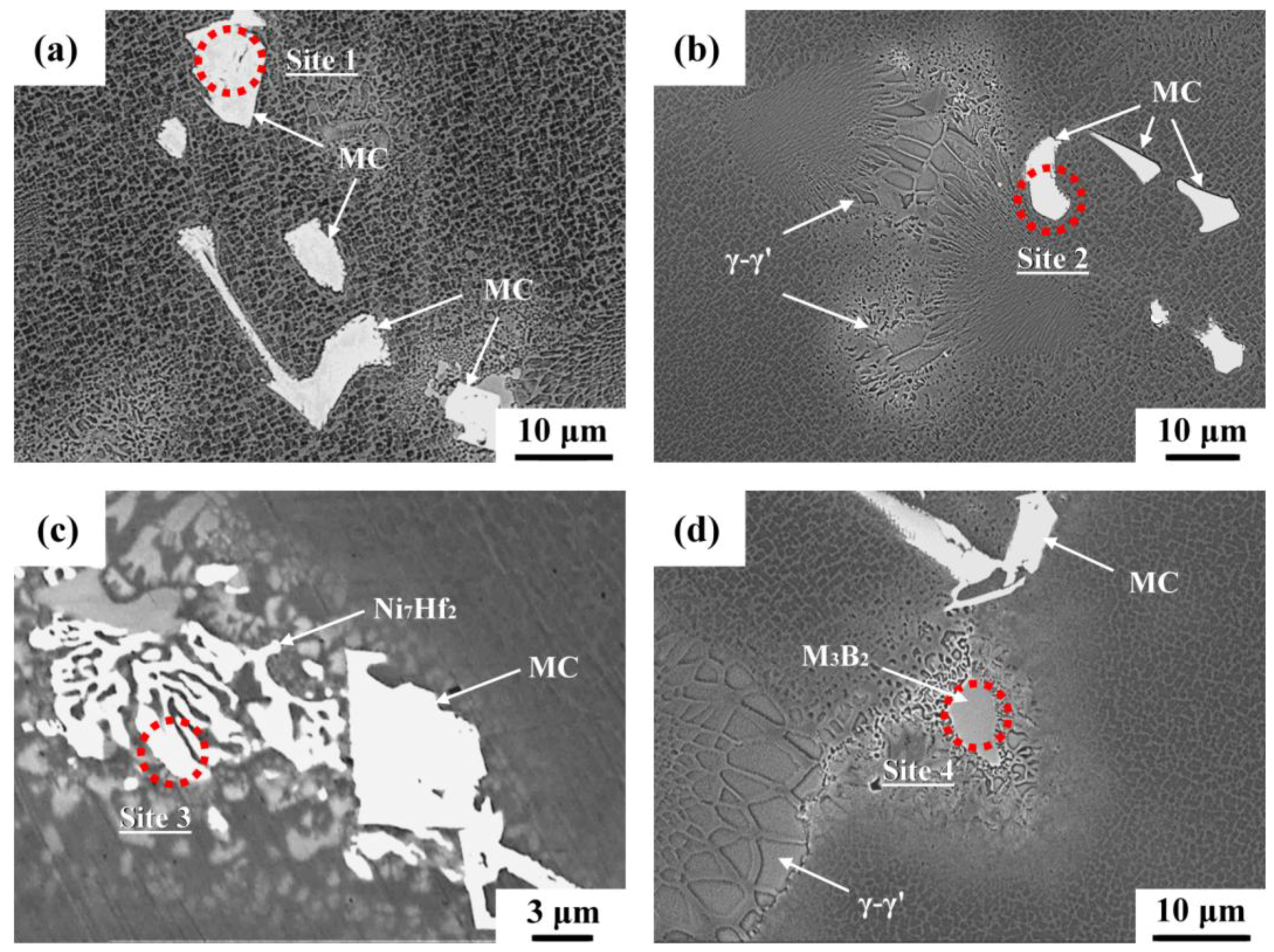
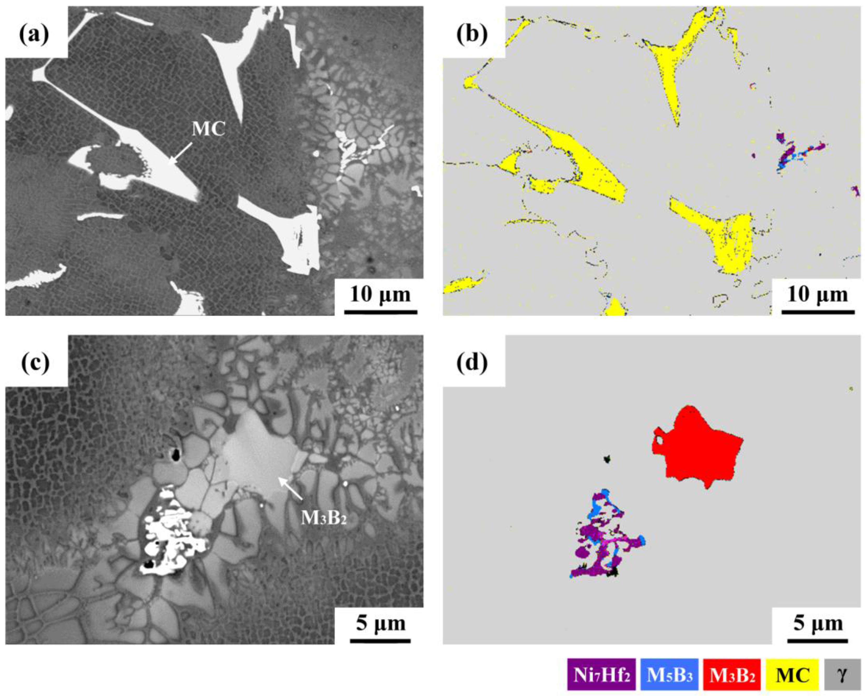
3.1. Metallographic Observations and EPMA Analyses

Figure 2 shows the cross-sectional view of a repair weld with IN625 as the filler metal. The FZ revealed that the microstructure was finer and more uniform than that of the cast BM with white solidified products at the boundaries (Figure 2a). The liquation cracks were more likely to propagate along the white phase in the HAZ of a Mar-M004 weldment as illustrated in Figure 2b. The hardness distribution from the FZ to the cast BM of the weld is displayed in Figure 2c. The hardness of the FZ, in which was deposited IN625 filler, was about HV 265. The cast Mar-M004 BM had a hardness of about HV 365. The HAZ near the fusion boundary had a slightly higher hardness than did the other zones. It was deduced that the welding heat caused the dissolution of coarse γ′ precipitates during the heating cycle and enhanced the formation of fine γ′ in the subsequent cooling cycle, resulting in the increased hardness therein.
Back-scatter electron (BSE) images were used to sort or characterize distinct solidification products according to the image brightness or the contrast of the possible solidification products. The typical microstructures in the cast Mar-M004 superalloy are shown in Figure 3. The MC carbides were the main second phase dispersed in the matrix and along the dendrite boundaries (Figure 3a,b). The MC carbides were present in distinct shapes, including island-like, blocky, and Chinese-script. Moreover, some MC carbides displayed the vague features of a lamellar structure at higher magnification. Thus, the segregation of carbide formers facilitated the formation of MC carbides or the occurrence of an MC-γ eutectic reaction. The γ-γ′ eutectic colonies could be seen frequently at the interdendritic boundaries (Figure 3b). As the solidification proceeded, the residual liquid naturally enriched the alloy elements, which promoted the formation of complex constituents at the boundaries. Those low-melting constituents included the lamellar intermetallic compounds (Figure 3c) and borides (Figure 3d) as confirmed in the following analysis.
EPMA quantitative chemical analyses were used in order to measure compositions of the complex constituents along interdendritic boundaries. Although the precise chemical compositions of the different phases might not be obtainable due to the interference with the surrounding matrix, the acquired information was helpful in identifying the terminal solidification products. Table 2 lists the chemical compositions (in at. %) of the EPMA results for distinct solidification products as indicated by arrows in Figure 3. The MC carbides (Figure 3a,b, at sites 1 and 2) were rich in Nb with extra Hf and Ti, which naturally revealed high brightness in the BSE image. The lamellar structure (site 3), with high brightness (Figure 3c), consisted of a certain amount of Hf and Zr. The low alloy contents of this measurement resulted from the high yield volume of the electron beam relative to the width of the lamellar structure. However, the co-segregation of Hf and Zr to the lamellar structure could not be neglected. The gray blocky product (site 4), composed of high concentrations of B, Cr, and Mo, could be reasonably concluded to be Cr-Mo borides.

3.2. EBSD Crystallographic Analyses

In Figure 4, different microstructures in the cast Mar-M004 were observed by SEM with the BSE mode and identified with the aid of EBSD analyses. The BSE image supported that the irregular bright phases with distinct morphologies (Figure 4a) were MC carbides, as further confirmed by their compositions (listed in Table 3) and EBSD identifications (Figure 4b). The EBSD map revealed that the yellow phases with different morphologies were all MC carbides, which were composed of significantly high Nb and Hf concentrations. It was noticed that few residual white phases could be seen ahead of the γ-γ′ eutectic colonies (Figure 4a,c). Such events indicated that those white phases solidified at a temperature lower than the γ-γ′ eutectic colonies. It has been reported that complex grain boundary constituents, such as MC carbides, M2SC sulphocarbides, Cr-Mo borides, Ni-Zr intermetallic compounds, and γ-γ′ (Ni3(Al,Ti)) eutectics, were obtained in IN738/IN738LC superalloy [13,14,16,25,26]. The EBSD map (Figure 4d) shows that the blocky gray product in Figure 4c was M3B2 boride, which was checked by EPMA measurements as listed in Table 3. The M3B2 boride consisted of very high Cr and Mo concentrations. White eutectic constituents in Figure 4c were proven to be Ni7Hf2 intermetallic compounds by the EBSD analysis shown in Figure 4d. Furthermore, fine M5B3 borides were inter-dispersed in the lamellar Ni7Hf2 compounds. The presence of borides at the interdendritic boundaries inevitably depressed the terminal solidification temperature, thus deteriorating the weldability of the cast superalloy.
As shown in Figure 3c, lamellar eutectics and solidification products in gray color are present ahead of γ-γ′ eutectic colonies, which are expected to be the terminal solidification products. Further analyses were oriented to understand the constituents of grain boundary products. Figure 5 presents micrographs showing the morphology, distributions of alloy elements, and phase constituents at the solidification boundary. The BSE image (Figure 5a) was useful in distinguishing the possible solidification products according to the image contrast. The EPMA maps (Figure 5b) displayed the distributions of distinct alloy elements. In addition, the EBSD map (Figure 5c) was able to identify the phase constituents of the solidification products. As shown in Figure 5a, several different products, namely irregular white phase, lamellar bright phase, and blocky gray phase, formed near the grain boundary. The Al distribution map indicated that the γ-γ′ eutectic colonies were rich in Al, but co-segregation of Ti was not found as a result of its low concentration. By contrast, co-segregation of Al and Ti was noticed in the γ-γ′ eutectic colonies of IN738 superalloy. The C map could be used to indicate the carbide sites. The results displayed that the C, Nb, and Hf maps showed the same trend of distribution. This meant that the carbides were rich in Nb and Hf. The irregular island-like white phase, indicated by an arrow in Figure 5a, was expected to be MC carbide. The Ti and Zr maps also revealed that Zr and Ti tended to participate in the carbides. Moreover, some fine carbide particles were inter-dispersed along the profile of the lamellar white phase. The EBSD map confirmed that the MC carbides formed in those sites of high C, Nb, and Hf concentrations (Figure 5c). The B map showed the distribution of B, which could be linked to the boride locations. The gray blocky product (Figure 5a), which enriched in B, Cr, and Mo in the corresponding maps in Figure 5b, was proven to be M3B2 boride (Figure 5c). The Zr and Hf maps displayed that the lamellar eutectic (indicated by an arrow in Figure 5a) was rich in Hf and Zr, which naturally showed high brightness in the BSE image in Figure 5a. The lamellar white phase in Figure 5a at the grain boundary region was identified as Ni-Hf-Zr (Ni7Hf2) intermetallics in Figure 5c. Moreover, it was found that M5B3 and M3B2 borides could be inter-dispersed in the Ni7Hf2 intermetallics as shown in Figure 5c.

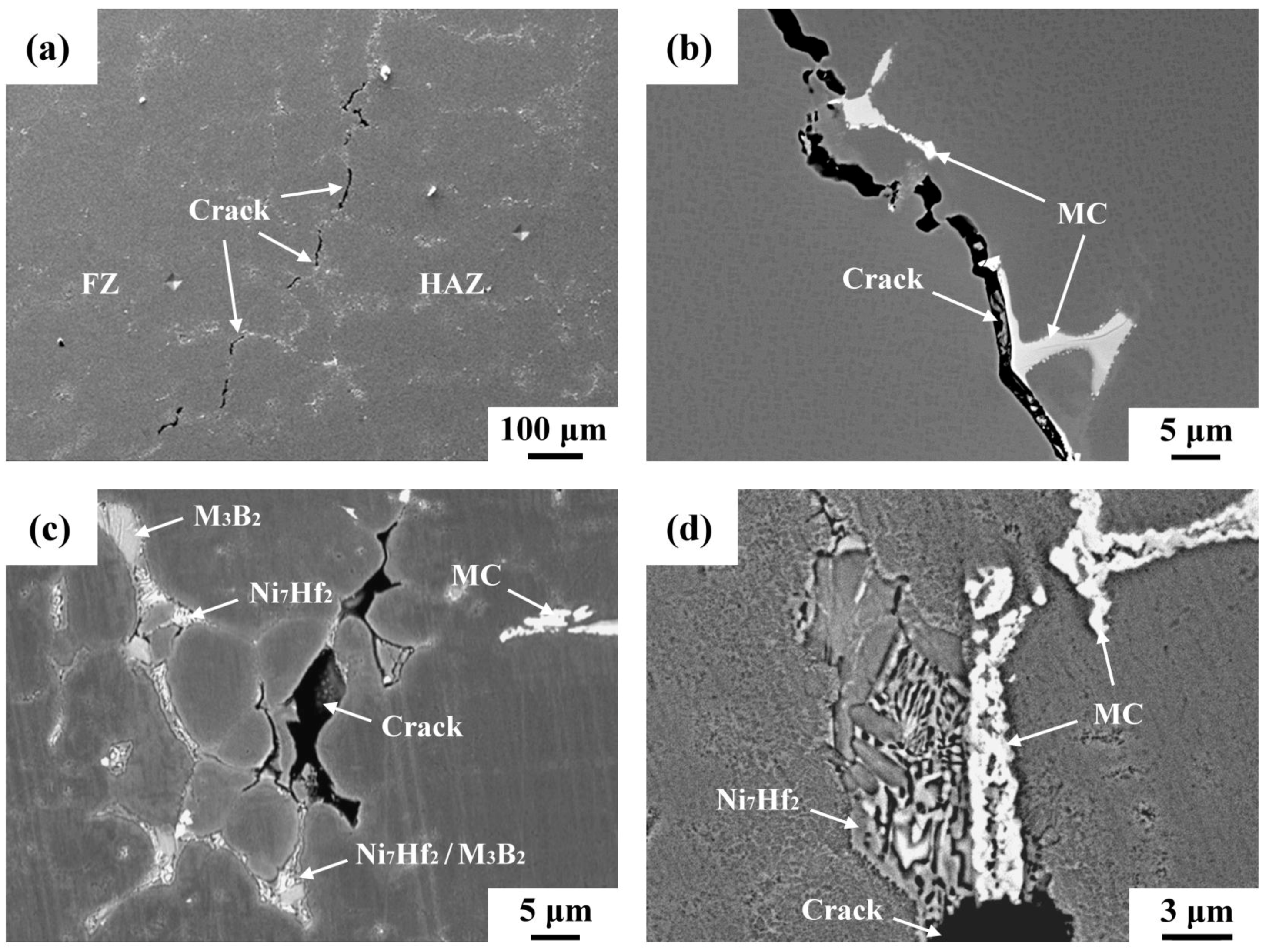
3.3. HAZ Microcracks

Mar-M004 welds were subjected to a standard metallographic procedure to reveal internal defects. Figure 6 shows SEM micrographs of microcracks in the HAZ next to the FZ of the repair weld. Obviously, microcracks propagated along interdendritic region of the HAZ (Figure 6a). The induced microcracks were clearly in association with the inherently metallurgical factors of the cast Mar-M004 superalloy. As reported in previous works [16,23,25,26], constitutional liquation of MC carbides, M3B2 borides, M2SC sulfocarbides, γ′ particles, and γ-γ′ eutectic accounts for the HAZ liquation cracking of IN738 superalloy welds. The cracks were found to be more likely to propagate along the interfaces between the MC carbides and the matrix (Figure 6b) owing to the substantial amounts of MC carbides in the cast Mar-M004 superalloy. The imposed shrinkage stress on the liquated phases promoted the occurrence of HAZ cracking of the Mar-M004 weld. Liquation cracking was also found to initiate and propagate along the boundaries between the γ-γ′ colonies (Figure 6c), wherein some minor phases in between might dominate the cracking. Inspection at higher magnifications showed that complex microconstituents in lamellar forms also played an important role on the HAZ liquation cracking as shown in Figure 6d.

3.4. SEM Fractographs of Liquated Cracks in the HAZ

After immersion in liquid nitrogen for a short time, the existing microcracks in the HAZ of the Mar-M004 weld were opened by applying a bending force. The fracture appearance of those microcracks was inspected by SEM in the BSE image, and EPMA maps were used to determine the chemical compositions of the coverings as shown in Figure 7. The fracture surface revealed the typical feature of hot cracking of a weld, i.e., solidified liquid droplets and eutectic constituents on the fracture surface (Figure 7a). The coverings on the fracture surface had different morphologies, including blocky, lamellar, and arrayed fine precipitates (Figure 7a,b). A few fine cracks were found to propagate through those solidification products, indicating the ease of cracking or brittleness of the solidification products. The high brightness of the eutectic constituents also implied the aggregation of high atomic weight elements. The EPMA maps (Figure 7c) indicated that the smooth fracture surface was enriched in Al but lean in other alloy elements. The cobble-like features enriched in Al were could be the separation between the γ-γ′ colonies. Additionally, the distributions of C and B were used to sort the types of microconstituents. The C map was used to identify the formation of isolated carbides or γ/MC eutectics. The results clearly showed the strong partitioning of Nb and Hf to the MC carbides in blocky or lamellar shapes. The B map indicated that the low-melting constituents on the fracture surface consisted of high B, Cr, and Mo concentrations, implying the formation of Cr-Mo borides. Moreover, a high tendency of B to segregate to those zones of carbides and intermetallics was noticed. It was also seen that the co-segregation of Hf and Zr (strong carbide formers) did not need to be accompanied by C segregation to form MC carbides simultaneously. Without the participation of C, the co-segregation of Hf and Zr shown in the EPMA maps would facilitate the formation of Ni-(Hf,Zr) lamellar intermetallic compounds instead of MC carbides.
It was obvious that localized melting of the grain boundary constituents during welding led to HAZ liquation cracking. The greater amount of carbides than that of other grain boundary constituents accounted for the higher trend of liquation cracking along the MC carbides than along other phases in the Mar-M004 weld. In addition, the terminal solidification temperature could be further depressed by the presence of other grain boundary products, such as borides and intermetallic compounds. Borides [10,11] are reported to liquate at lower temperature and extend the brittle temperature range, so the susceptibility of liquation cracking in the HAZ is increased [25,26]. In this work, the weldability of cast Mar-M004 superalloy is greatly impaired by the segregation of B to the grain boundary carbides and intermetallics along with the formation of M3B2 and M5B3 borides.

3.5. Pre-Weld Heat Treatment

In prior work [33], premature melting of final solidification products, such as γ-γ′ colonies, MC carbides, Cr-Mo borides, and Ni-Hf intermetallic compounds at the dendrite boundaries, accounted for the HAZ cracking of a Mar-M004 weldment. Pre-weld heat treatments were performed to eliminate those harmful microstructures and thereby improve the weldability of the cast superalloys [16,27,31,34]. In this work, pre-weld heat treatment was carried out at 1180 °C/4 h in hard vacuum followed by Ar-assisted cooling to room temperature. After metallographic preparations, the initial microstructures of the sample were inspected by SEM in BSE images, with special attention paid to the grain boundary microconstituents. After solution treatment, the same sample was examined again to reveal the variation in microstructures at the same site. Figure 8 illustrates the evolution of microstructures before/after pre-weld heat treatment. In Figure 8a, MC carbides, borides, and lamellar intermetallics were present in the sample before pre-weld treatment. After solution treatment at 1180 °C/4 h in high vacuum, the borides and lamellar intermetallics ahead of γ-γ′ colonies liquated unexpectedly. This event caused the formation of micro-pores in the sample (Figure 8b). The MC carbides still resisted melting during this solution treatment. After the damaged sample was polished, the surface morphologies of the solution-treated sample were investigated in BSE images and subjected to EBSD analysis; the results are shown in Figure 8c,d. The figures revealed that those regions ahead of γ-γ′ colonies liquated preferentially (Figure 8c). The EBSD map (Figure 8d) showed that liquation cracking was strongly related to the melting of borides and lamellar intermetallics.
The MC carbides were the major second phases of the cast Mar-M004 superalloy, thus cracks were more likely to propagate along the γ-MC carbide interface. In fact, the borides and lamellar intermetallics were formed ahead of γ-γ′ colonies, which were more likely to melting during welding. In this work, attention was paid to the premature liquation of the borides and lamellar intermetallics. To improve the weldability of the cast Mar-M004 superalloy, those low-melting microconstituents needed to be reduced by a proper pre-weld heat treatment. It was obvious that solution-treatment at 1180 °C was too high to remove harmful phases from the Mar-M004 alloy. A proper pre-weld heat treatment should be conducted on the first priority if refurbishment of the turbine needs to be applied. It also implied that local overheating of the investigated alloy above 1180 °C during welding or service would introduce microcracks into the components. Further work to eliminate those two harmful phases by proper heat treatments is planned to improve the weldability of Ni-based superalloys. In addition to repair welding, turning and milling are also crucial operations in refurbishing such a turbine blade. Fortunately, these key manufacturing processes have been successfully developed by using multitasking and/or super-abrasive machine centers [35,36]. The combination of the above manufacturing processes will make a great achievement in the refurbishment of such turbine blades.

4. Conclusions

(1)
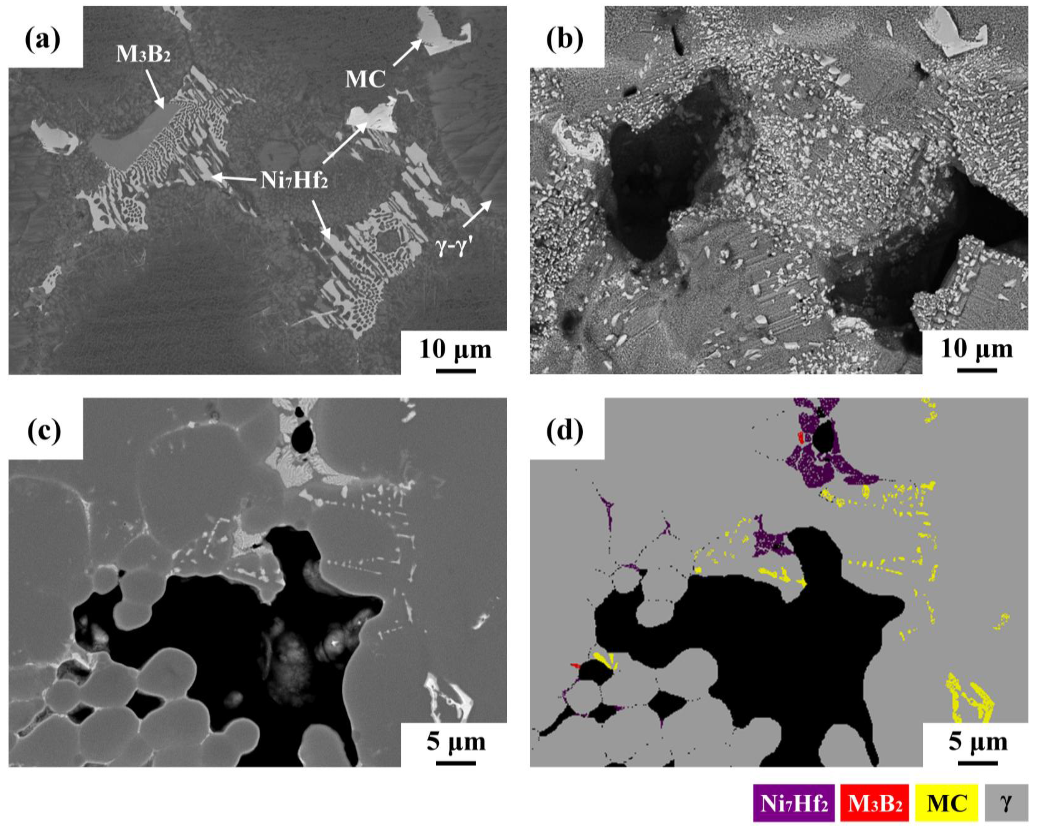
Liquation cracks in the HAZ of a repaired Mar-M004 weld resulted from low-melting constituents along solidification boundaries. Premature melting of final solidification products, such as γ-γ′ eutectic colonies, MC carbides, Cr-Mo borides, and Ni-Hf intermetallic compounds at the dendrite boundaries, were responsible for the HAZ liquation cracking of the weld.
(2)
Cracks were more likely to propagate along the interface between γ and MC carbides because the MC carbides were the major second phase of the cast Mar-M004 superalloy. Moreover, the borides and lamellar intermetallics formed ahead of γ-γ′ colonies were melted preferentially at a much lower temperature during welding.
(3)
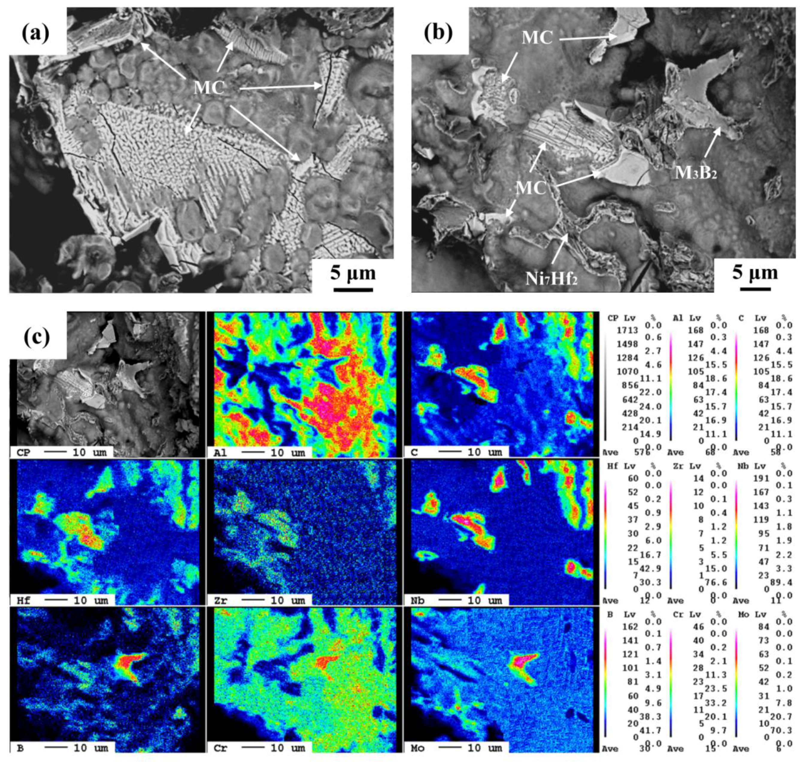
Fractographs of liquation cracks displayed solidified droplets and eutectic constituents. The smooth fractured surface was enriched in Al but lean in other alloying elements, which was associated with γ-γ′ colonies. Nb/Hf combined with C to form blocky MC carbides or assist the γ/MC eutectic reactions. Without the participation of C, co-segregation of Hf and Zr enhanced the formation of Ni-(Hf,Zr) intermetallics in lamellar form. In addition to the formation of Cr-Mo borides, the fractured surface contained a certain amount of B, which implied a strong tendency of B segregation to the final solidification products.
(4)
Pre-weld heat treatment of the cast superalloy at 1180 °C/4 h resulted in melting of borides (M3B2 and M5B3) and lamellar intermetallics (Ni7Hf2) ahead of γ-γ′ colonies. In contrast, MC carbides were more resistant to melting during the pre-weld heat treatment.
(5)
To achieve a crack-free weld, a proper pre-weld heat treatment for such a cast superalloy should be customized on the first priority if refurbishment of the turbine is required.

Acknowledgments

The authors appreciate the funding support of this study by the Ministry of Science and Technology, R.O.C. (Contract No. MOST 104-2221-E-019-003). Chung-Yuan Kao’s assistance in EPMA analyses at National Taiwan University is also greatly acknowledged.

Author Contributions

Ren-Kae Shiue and Leu-Wen Tsay designed the experiments and explained their results. Tai-Cheng Chen and Yi-Hsin Cheng carried out the test.

Conflicts of Interest

The authors declare no conflict of interest.

References

  1. Balikci, E.; Raman, A.; Mirshams, R.A. Influence of various heat treatments on the microstructure of polycrystalline IN738LC. Metall. Mater. Trans. A 1997, 28, 1993–2003. [Google Scholar] [CrossRef]
  2. Balikci, E.; Raman, A. Characteristics of the γ′ precipitates at high temperatures in Ni-base polycrystalline superalloy IN738LC. J. Mater. Sci. 2000, 35, 3593–3597. [Google Scholar] [CrossRef]
  3. Sajjadi, S.A.; Nategh, S.; Guthrie, R.I.L. Study of microstructure and mechanical properties of high performance Ni-base superalloy GTD-111. Mater. Sci. Eng. A 2002, 325, 484–489. [Google Scholar] [CrossRef]
  4. Monajati, H.; Jahazi, M.; Bahrami, R.; Yue, S. The influence of heat treatment conditions on γ′ characteristics in Udimet® 720. Mater. Sci. Eng. A 2004, 373, 286–293. [Google Scholar] [CrossRef]
  5. Wongbunyakul, P.; Visuttipitukkul, P.; Wangyao, P.; Lothongkum, G.; Sricharoenchai, P. Effect of reheat treatment on microstructural refurbishment and hardness of the as-cast Inconel 738. High Temp. Mater. Process. 2014, 33, 453–461. [Google Scholar] [CrossRef]
  6. Kotval, P.S.; Venables, J.D.; Calder, R.W. The role of hafnium in modifying the microstructure of cast nickel-base superalloys. Metall. Mater. Trans. B 1972, 3, 457–462. [Google Scholar] [CrossRef]
  7. Balikci, E.; Mirshams, R.A.; Raman, A. Fracture behavior of superalloy IN738LC with various precipitate microstructures. Mater. Sci. Eng. A 1999, 265, 50–62. [Google Scholar] [CrossRef]
  8. Zupanič, F.; Bončina, T.; Križman, A.; Tichelaar, F.D. Structure of continuously cast Ni-based superalloy Inconel 713C. J. Alloys Compd. 2001, 329, 290–297. [Google Scholar] [CrossRef]
  9. El-Bagoury, N.; Nofal, A. Microstructure of an experimental Ni base superalloy under various casting conditions. Mater. Sci. Eng. A 2010, 527, 7793–7800. [Google Scholar] [CrossRef]
  10. Zhang, H.R.; Ojo, O.A.; Chaturvedi, M.C. Nanosize boride particles in heat-treated nickel base superalloys. Scr. Mater. 2008, 58, 167–170. [Google Scholar] [CrossRef]
  11. Du, B.; Shi, Z.; Yang, J.; Chu, Z.; Cui, C.; Sun, X.; Sheng, L.; Zheng, Y. M5B3 boride at the grain boundary of a nickel-based superalloy. J. Mater. Sci. Technol. 2016, 32, 265–270. [Google Scholar] [CrossRef]
  12. Jahangiri, M.R.; Arabi, H.; Boutorabi, S.M.A. Investigation on the dissolution of η phase in a cast Ni-based superalloy. Int. J. Miner. Metall. Mater. 2013, 20, 42–48. [Google Scholar] [CrossRef]
  13. Ojo, O.A.; Richards, N.L.; Chaturvedi, M.C. Contribution of constitutional liquation of gamma prime precipitate to weld HAZ cracking of cast Inconel 738 superalloy. Scr. Mater. 2004, 50, 641–646. [Google Scholar] [CrossRef]
  14. Ojo, O.A.; Richards, N.L.; Chaturvedi, M.C. Microstructural study of weld fusion zone of TIG welded IN 738LC nickel-based superalloy. Scr. Mater. 2004, 51, 683–688. [Google Scholar] [CrossRef]
  15. Rush, M.T.; Colegrove, P.A.; Zhang, Z.; Broad, D. Liquation and post-weld heat treatment cracking in Rene 80 laser repair welds. J. Mater. Process. Technol. 2012, 212, 188–197. [Google Scholar] [CrossRef] [Green Version]
  16. Montazeri, M.; Ghaini, F.M. The liquation cracking behavior of IN738LC superalloy during low power Nd:YAG pulsed laser welding. Mater. Charact. 2012, 67, 65–73. [Google Scholar] [CrossRef]
  17. Osoba, L.O.; Ding, R.G.; Ojo, O.A. Microstructural analysis of laser weld fusion zone in Haynes 282 superalloy. Mater. Charact. 2012, 65, 93–99. [Google Scholar] [CrossRef]
  18. Angella, G.; Barbieri, G.; Donnini, R.; Montanari, R.; Richetta, M.; Varone, A. Electron beam welding of IN792 DS: Effects of pass speed and PWHT on microstructure and hardness. Materials 2017, 10, 1033. [Google Scholar] [CrossRef] [PubMed]
  19. Liu, D.; Lippold, J.C.; Li, J.; Rohklin, S.R.; Vollbrecht, J.; Grylls, R. Laser engineered net shape (LENS) technology for the repair of Ni-base superalloy turbine components. Metall. Mater. Trans. A 2014, 45, 4454–4469. [Google Scholar] [CrossRef]
  20. Ding, R.G.; Huang, Z.W.; Li, H.Y.; Mitchell, I.; Baxter, G.; Bowen, P. Electron microscopy study of direct laser deposited IN718. Mater. Charact. 2015, 106, 324–337. [Google Scholar] [CrossRef]
  21. Jalilvand, V.; Omidvar, H.; Shakeri, H.R.; Rahimipour, M.R. Microstructural evolution during transient liquid phase bonding of Inconel 738LC using AMS 4777 filler alloy. Mater. Charact. 2013, 75, 20–28. [Google Scholar] [CrossRef]
  22. Henderson, M.B.; Arrell, D.; Larsson, R.; Heobel, M.; Marchant, G. Nickel based superalloy welding practices for industrial gas turbine applications. Sci. Technol. Weld. Join. 2004, 9, 13–21. [Google Scholar] [CrossRef]
  23. Li, Q.; Lin, X.; Wang, X.; Yang, H.; Song, M.; Huang, W. Research on the grain boundary liquation mechanism in heat affected zones of laser forming repaired K465 nickel-based superalloy. Metals 2016, 6, 64. [Google Scholar] [CrossRef]
  24. Lachowicz, M.; Dudziński, W.; Podrez-Radziszewska, M. TEM observation of the heat-affected zone in electron beam welded superalloy Inconel 713C. Mater. Charact. 2008, 59, 560–566. [Google Scholar] [CrossRef]
  25. Ojo, O.A.; Richards, N.L.; Chaturvedi, M.C. Study of the fusion zone and heat-affected zone microstructures in tungsten inert gas-welded INCONEL 738LC superalloy. Metall. Mater. Trans. A 2006, 37, 421–433. [Google Scholar] [CrossRef]
  26. Ojo, O.A.; Richards, N.L.; Chaturvedi, M.C. On incipient melting during high temperature heat treatment of cast Inconel 738 superalloy. J. Mater. Sci. 2004, 39, 7401–7404. [Google Scholar] [CrossRef]
  27. Shahsavari, H.A.; Kokabi, A.H.; Nategh, S. Effect of preweld microstructure on HAZ liquation cracking of Rene 80 superalloy. Mater. Sci. Technol. 2007, 23, 547–555. [Google Scholar] [CrossRef]
  28. Wang, W.; Li, C.; Jiang, L.; Ye, X.-X.; Yu, K.; Chen, S.; Li, Z.; Zhou, X. Evolution of carbide precipitates in Hastelloy N joints during welding and post weld heat treatment. Mater. Charact. 2018, 135, 311–316. [Google Scholar] [CrossRef]
  29. Xu, H.; Liu, W.; Lu, F.; Wang, P.; Ding, Y. Evolution of carbides and its characterization in HAZ during NG-TIG welding of Alloy 617B. Mater. Charact. 2017, 130, 270–277. [Google Scholar] [CrossRef]
  30. Xu, J.; Lin, X.; Guo, P.; Hu, Y.; Wen, X.; Xue, L.; Liu, J.; Huang, W. The effect of preheating on microstructure and mechanical properties of laser solid forming IN-738LC alloy. Mater. Sci. Eng. A 2017, 691, 71–80. [Google Scholar] [CrossRef]
  31. Danis, Y.; Arvieu, C.; Lacoste, E.; Larrouy, T.; Quenisset, J.-M. An investigation on thermal, metallurgical and mechanical states in weld cracking of Inconel 738LC superalloy. Mater. Des. 2010, 31, 402–416. [Google Scholar] [CrossRef]
  32. Sidhu, R.K.; Richards, N.L.; Chaturvedi, M.C. Effect of filler alloy composition on post-weld heat treatment cracking in GTA welded cast Inconel 738LC superalloy. Mater. Sci. Technol. 2008, 24, 529–539. [Google Scholar] [CrossRef]
  33. Cheng, Y.H.; Chen, J.T.; Shiue, R.K.; Tsay, L.W. The Evolution of Cast Microstructures on the HAZ Liquation Cracking of Mar-M004 Weld. Metals 2018, 8, 35. [Google Scholar] [CrossRef]
  34. González, M.A.; Martínez, D.I.; Pérez, A.; Guajardo, H.; Garza, A. Microstructural response to heat affected zone cracking of prewelding heat-treated Inconel 939 superalloy. Mater. Charact. 2011, 62, 1116–1123. [Google Scholar] [CrossRef]
  35. Gonzalez, H.; Calleja, A.; Pereira, O.; Ortega, N.; de Lacalle, L.N.L.; Barton, M. Super abrasive machining of integral rotary components using grinding flank tools. Metals 2018, 8, 24. [Google Scholar] [CrossRef]
  36. Calleja, A.; Fernandez, A.; Rodriguez, A.; de Lacalle, L.N.L.; Lamikiz, A. Turn-milling of blades in turning centres and multitasking machines controlling tool tilt angle. J. Eng. Manuf. 2015, 229, 1324–1336. [Google Scholar] [CrossRef]
Figure 1. (a) The macro-view of the cast turbine; (b) the tested sample cut from the turbine; (c) the joint geometry of the repair weld; and (d) the macro-view of the repair weld.
Metals 08 00201 g001
Figure 2. (a) Cross-sectional view of the repair weld; (b) liquation crack in the heat-affected zone (HAZ) of the weldment; (c) microhardness indentations from the fusion zone (FZ) across the weld interface to the base metal (BM).
Metals 08 00201 g002
Figure 3. SEM images illustrating the cast microstructures of the Mar-M004 superalloy: (a) the metal carbides (MC) carbides in different shapes; (b) a γ-γ′ eutectic at the boundaries; (c) lamellar eutectics and MC carbide at the boundaries; and (d) the presence of borides at the boundaries.
Metals 08 00201 g003
Figure 4. The analysis of solidification products in the cast superalloy: (a) back-scatter electron (BSE) image of MC carbides and their associated (b) electron backscatter diffraction (EBSD) map; (c) BSE image showing the boundary microconstituents and related (d) EBSD map showing the presence of borides and lamellar intermetallics.
Metals 08 00201 g004
Figure 5. The identification of complex grain boundary microconstituents: (a) BSE image showing the interdendritic microconstituents ahead of γ-γ′ colonies; (b) the elemental maps of the boundary microconstitutents determined by electron probe micro-analyzer (EPMA); and (c) the EBSD map to distinguish the MC carbide, borides, and lamellar intermetallics.
Metals 08 00201 g005
Figure 6. (a) The occurrence of liquated cracks in the HAZ of the Mar-M004 weld; (b) crack growth along the interface between the MC carbide and matrix; (c) lamellar white phases and carbides ahead of liquated crack; and (d) complex microconstituents ahead of liquation crack.
Metals 08 00201 g006
Figure 7. (a,b) SEM fractographs of liquated cracks and (c) the associated elemental mappings determined by EPMA.
Metals 08 00201 g007
Figure 8. (a) BSE image of the cast microstructure; (b) the microstructural change of the (a) sample after solution-treatment at 1180 °C for 4 h; (c) BSE image of the liquated sample after metallographic preparation; and (d) EBSD map of the (c) sample.
Metals 08 00201 g008
Table 1. The chemical compositions of Mar-M004 in wt. %.
Alloy/ElementAlBCCrHfMoNbTiZrNi
Mar-M0045.950.0150.0512.01.34.52.00.60.05Bal
Table 2. Chemical compositions in at. % of solidification products displayed in Figure 3.
Location/ElementAlBCCrHfMoNbTiZrNi
Site 11.2044.520.575.064.2329.105.960.41Bal
Site 20.273.3744.851.293.866.5427.937.380.20Bal
Site 31.578.264.577.402.111.810.803.79Bal
Site 40.5440.930.0121.470.2627.212.240.180.08Bal
Table 3. Chemical compositions in at. % of the solidified phases as displayed in Figure 4.
Phase/ElementAlBCCrHfMoNbTiZrNi
MC0.0344.340.7718.743.6923.373.521.70Bal
M3B20.0225.431.0331.810.0933.852.380.30Bal

