Abstract
Friction stir welding of aluminum alloys has been progressively used in different industries on the ground of higher welding quality in comparison to fusion welding. In this article, friction stir welding of 6061-T6 aluminum alloy with 9.6 mm thickness was carried out by using three different welding speeds (63, 89 and 110 mm/min). The effect of welding speed on macro- and microstructure, micro hardness, tensile properties and kissing bond was investigated. Results show that the Low Hardness Zone was moved toward the weld center by increasing the welding speed. The average micro hardness in the weld nugget zone increased from 60.1 to 67.6 HV with the raise of welding speed from 63 to 110 mm/min. Thermo Mechanical Affected Zone was clearly revealed using Electron backscatter diffraction (EBSD). The kissing bond was studied by Scanning Electron Microscopy (SEM) and Energy Dispersive X-ray (EDX) mapping. It was proven that the damaging effect of kissing bond was linked to location of this discontinuity, although the growth of kissing bond was linked to higher welding speed. The maximum value of Ultimate Tensile Strength (UTS) (159 MPa) was obtained at 110 mm/min, whereas the Yield Strength (YS) in the sample at 89 and 110 mm/min welding speed exhibit the same trend with 137 MPa and 134 MPa respectively.
1. Introduction
AA6061, one of most common alloy among AA6XXX series aluminum alloys, shows special properties in industrial application such as high strength to weight ratio, plasticity, capacity for crucial shape forming along its ease for joining and good corrosion resistance [1,2,3]. It is increasingly used for versatile applications such as design of armor structures, shipbuilding, aerospace, automotive industries, lightweight defense vehicles and marine structures [1,2,3]. Both fusion and solid state joining are used for welding of AA6061-T6.
In Friction stir welding (FSW), a solid state welding process, a non-consumable rotating welding tool is used to produce a weld that creates frictional heat and changes the welding location, thereby changing the joint, while the material is in the solid state. Because of the lower level of heating generated by the FSW process (80% of melting point), less overall energy is consumed compared with fusion welding process. Regarding the advantages and efficiency of process, FSW could be considered a very “green” process without ignoring in the modern industry [4,5,6,7,8].
FSW in comparison to conventional fusion welding processes has more advantages. Implementing proper parameters, a weld with lower distortion and higher quality can be obtained with a faster welding speed while requiring less operator skill. However, the inadequate parameters’ combination in welding process might result in defects observed based on the welding configuration. In the butt weld configuration, common imperfections are voids and wormholes in addition to lack of penetration and joint line remnant defects (also known as kissing bond, lazy S or entrapped oxide defects). In fact, the lack of deformation and string of the contacting surfaces in joint line are understood as the main cause resulting in insufficient oxide layer (Al2O3 in aluminum alloys) breaking and prohibiting metallic bonds from forming between the metal of both contacting surfaces [9,10]. The existence of kissing bond is more important when it is located in the root of weld.
In both fusion and solid state processes, the main metallurgical issue is the softening or solution of precipitants in heat affected zone (HAZ) and weld zone (WZ) of joint, although the heat is lower in FSW. The proper parameters’ variables during welding can minimize the soften zones as well as the kissing bond. Welding speed along with rotational speed are critical parameters in FSW [9,11,12,13,14,15]. Decrease in heat input is the respected benefit of increase in welding speed and decrease in rotational speed [11].
In current study, the effects of welding speed on the microstructure and mechanical properties of FSW AA6061-T6 aluminum alloy joints were studied. Three different welding speeds (63, 89 and 110 mm/min) were used. The microstructure, hardness and tensile properties were investigated; moreover, kissing bond and its effect on tensile properties were illustrated.
2. Material and Methods
The welding was performed on AA6061-T6 plate of 9.6 mm thickness. Table 1 shows the nominal composition of the base metal used in this study; mechanical properties of base metal can be seen in Table 2.

Table 1.
Nominal chemical composition of materials used in FSW experiments (wt. %).
Table 2.
Mechanical properties of the 6061-T6 aluminum alloy.
Figure 1 presents the AA6061-T6 alloy microstructure. Within the grains, white and grey spots are evident. These spots represent the constituent intermetallic particles. Some of them were seen being attacked by the etching processes (P in Figure 1). As can be seen, grains were slightly elongated in a direction parallel to the rolling direction. The alloy fabrication process has shown its impact on the distribution of intermetallic particles as well. The intermetallic particles were seen aligned along the rolling direction (Q in Figure 1). It is clear that at the longitudinal plane, the grains were seen elongated in a direction parallel to the rolling direction and the intermetallic particles were aligned along the rolling direction.
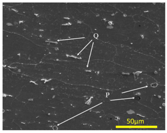
Figure 1.
Scanning Electron Microscopy (SEM) image of base metal AA6061-T6.
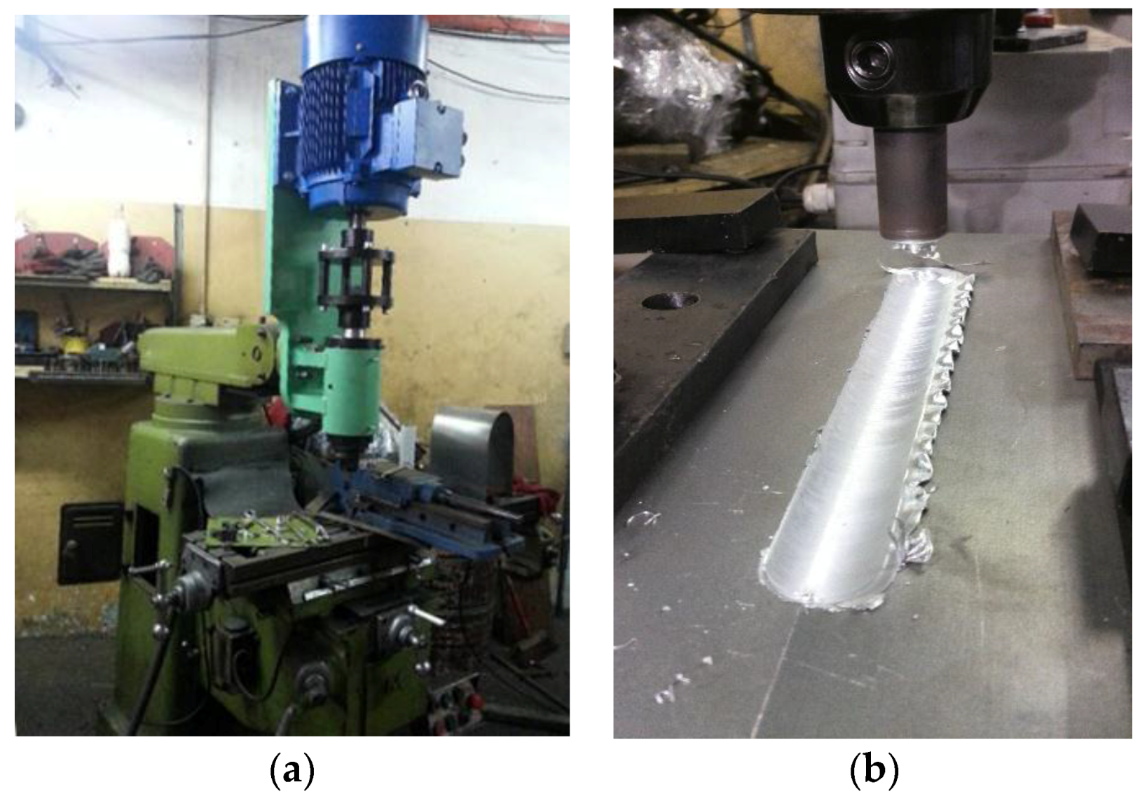
The joining process was carried out in a conventional machine, as a FSW machine shown in Figure 2a. The head of machine (pin holder) was redesigned with a new cooling system to support high pressure and force which are needed during FSW of this high thickness joint. The plates were fabricated in butt joint design with (300 × 150 × 9.6) mm3 dimensions. The fixation system and the welding process are presented in Figure 2b.
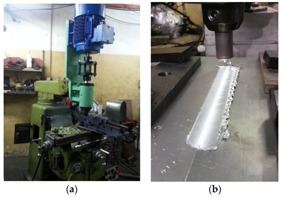
Figure 2.
(a) A vertical milling machine used for FSW experiments. (b) The real shape of fixture (clamping) used to restrain the plates during FSW.
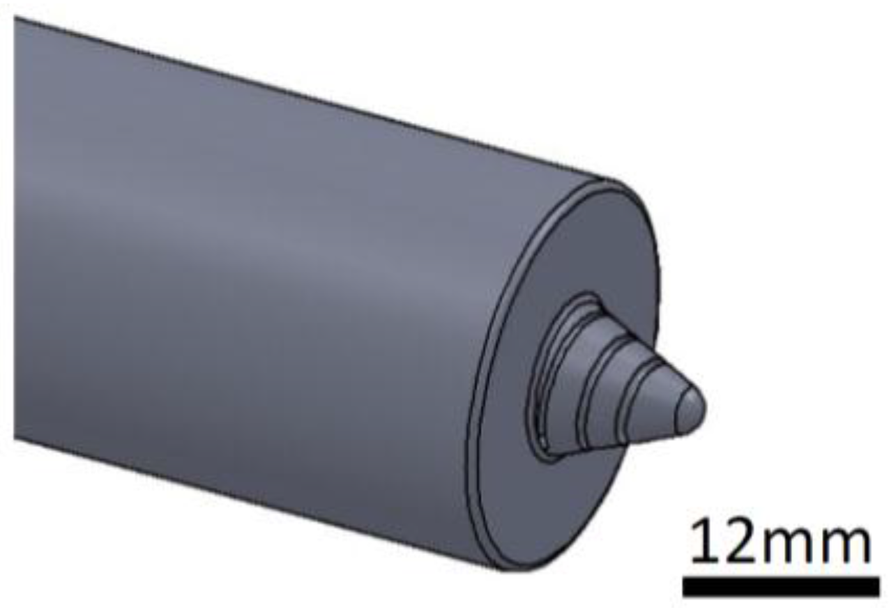
As can be seen in Figure 3, the pin tip of the welding process has a conic shape with clockwise threads in order to improve the material flow. To obtain a better quality, the extreme pin tip is rounded [16]. The key dimensions of the welding tool are summarized in Table 3.
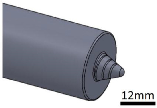
Figure 3.
Shape of the welding tool designed in this work.
Table 3.
Summary of dimensions of the tools used in Friction Stir Welding (FSW) experiments.
It should be noted that during the welding process, the tool rotation was kept unchanged (1480 rpm, counter clockwise). Further, the tool shoulder with three degree tilt angle was plunged into the joint of plate by a depth of around 0.1 mm. Dwell time at the start point of welding was 10 s. Three different welding speed were applied in this study; 63, 89 and 110 mm/min.
After doing FSW, the samples were cut perpendicularly to the weld line, to study the macro- and microstructure evolution along the welded joints. After grinding and final polishing up to one micron using diamond paste, samples were etched in Keller’s reagent for two minutes. Optical microscope (Leica DM1750 M, Buffalo Grove, IL, USA) and Scanning Electron Microscopy (FEI, Nova NanoSEM 230, Hillsboro, OR, USA) with Energy Dispersive X-Ray spectroscopy (FEI, Nova NanoSEM 230, Hillsboro, OR, USA) mapping were used for observing and analyzing the microstructures. For Electron Backscatter Diffraction (EBSD, Variable Pressure Scanning Electron Microscope–Hitachi S3200N, Raleigh, NC, USA) analysis, the samples were cut perpendicularly to the weld bead. After the polishing described above, a final polishing is performed by using 0.5 micron colloidal silica on the VibroMet® 2 Vibratory Polisher (Buehler, Lake Bluff, IL, USA) for six hours. The EBSD was done by Variable Pressure SEM and the resulting data were acquired using the EDAX TEAM software (TEAM™ EBSD, Mahwah, NJ, USA).
For mechanical investigation, tensile tests were performed at room temperature using a 100 KN Instron universal testing machine with the frame rail speed fixed at 2.0 mm/min. The number of tests and the dimensions of the samples for tensile test were selected in accordance with ISO 4136 standard [17]. The fractured surfaces were investigated using SEM. Classical microhardness measurements were performed in a cross-section perpendicular to the weld line every 1 mm by applying an indentation load of 500 gf and a dwell-time of 10 s.
3. Results and Discussion
3.1. Macrostructure
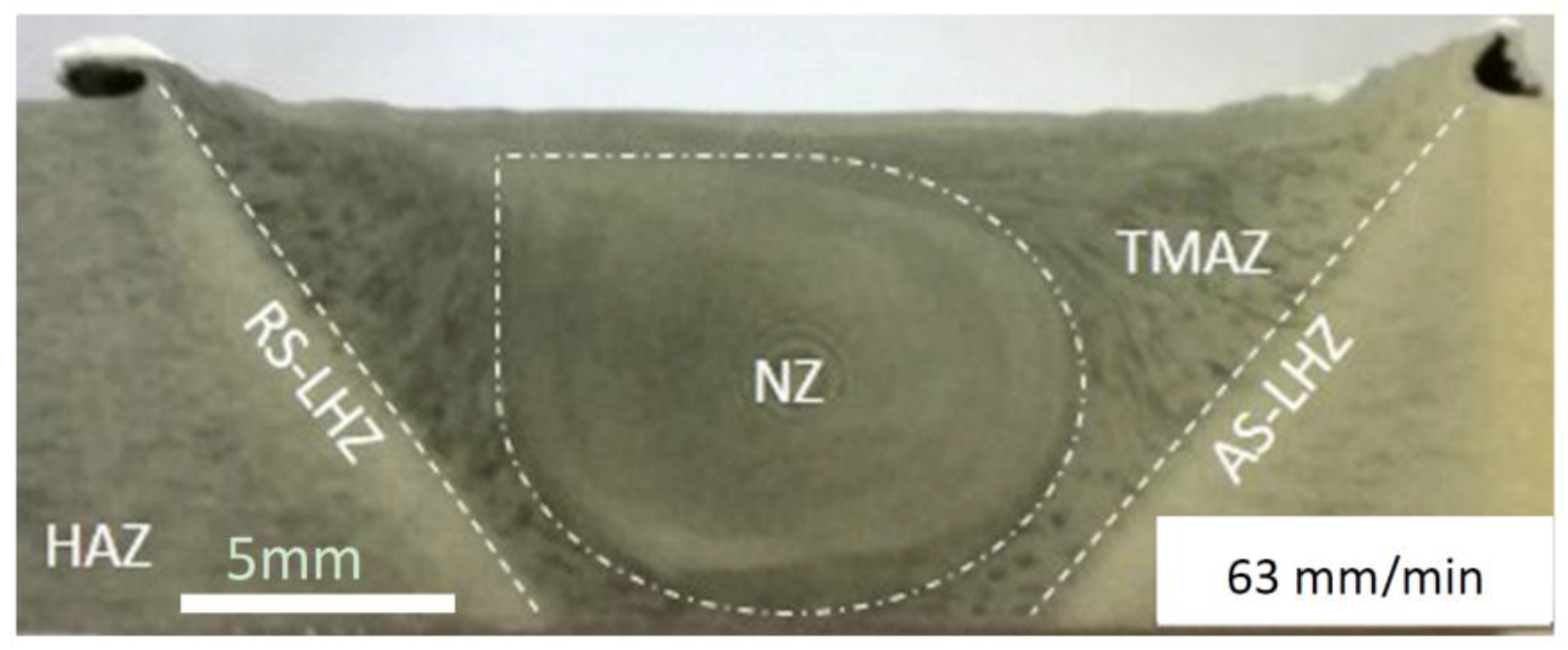
Figure 4 shows macrograph of a cross section weld of this study with 63 mm/min welding speed. The weldment regions consist of three typical zones including the heat affected zone (HAZ), the thermo-mechanically affected Zone (TMAZ), and the nugget zone (NZ). Macroscopic inspection of the weld zone revealed a comparative non-symmetric nugget zone (NZ) that was mainly related to the tilt angle of the tool and the relation between direction of tool rotation and welding direction [9,18]. Similar observations have been documented by other researchers [19,20,21,22]. The border between HAZ and TMAZ zones, is known as a Low Hardness Zone (LHZ) (Figure 4) [23]. In Figure 4, the LHZ of retreating side is RS-LHZ, whereas the AS-LHZ is the LHZ located in advancing side.

Figure 4.
Macrograph of friction stir welded joint in 63 mm/min.
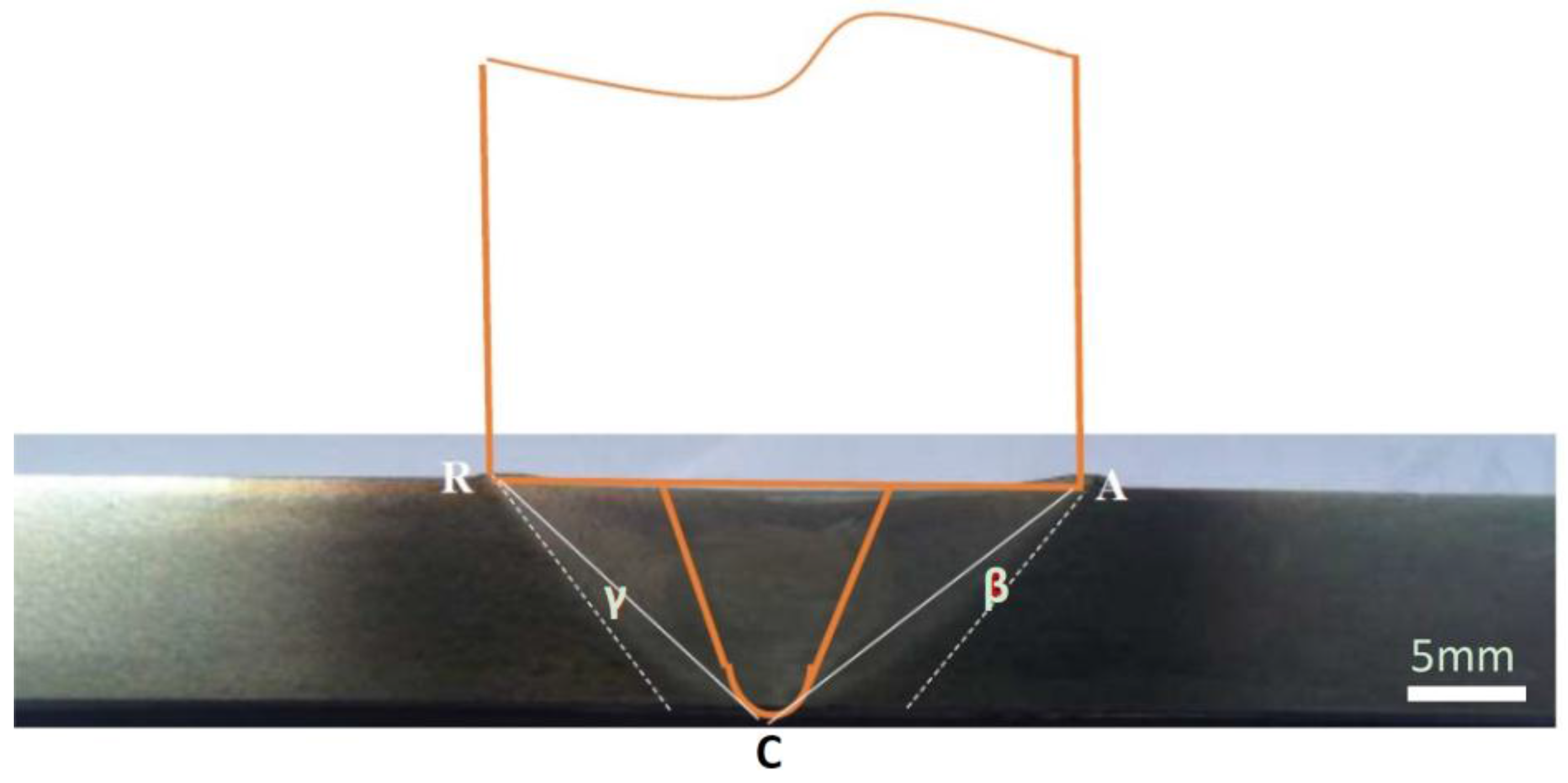
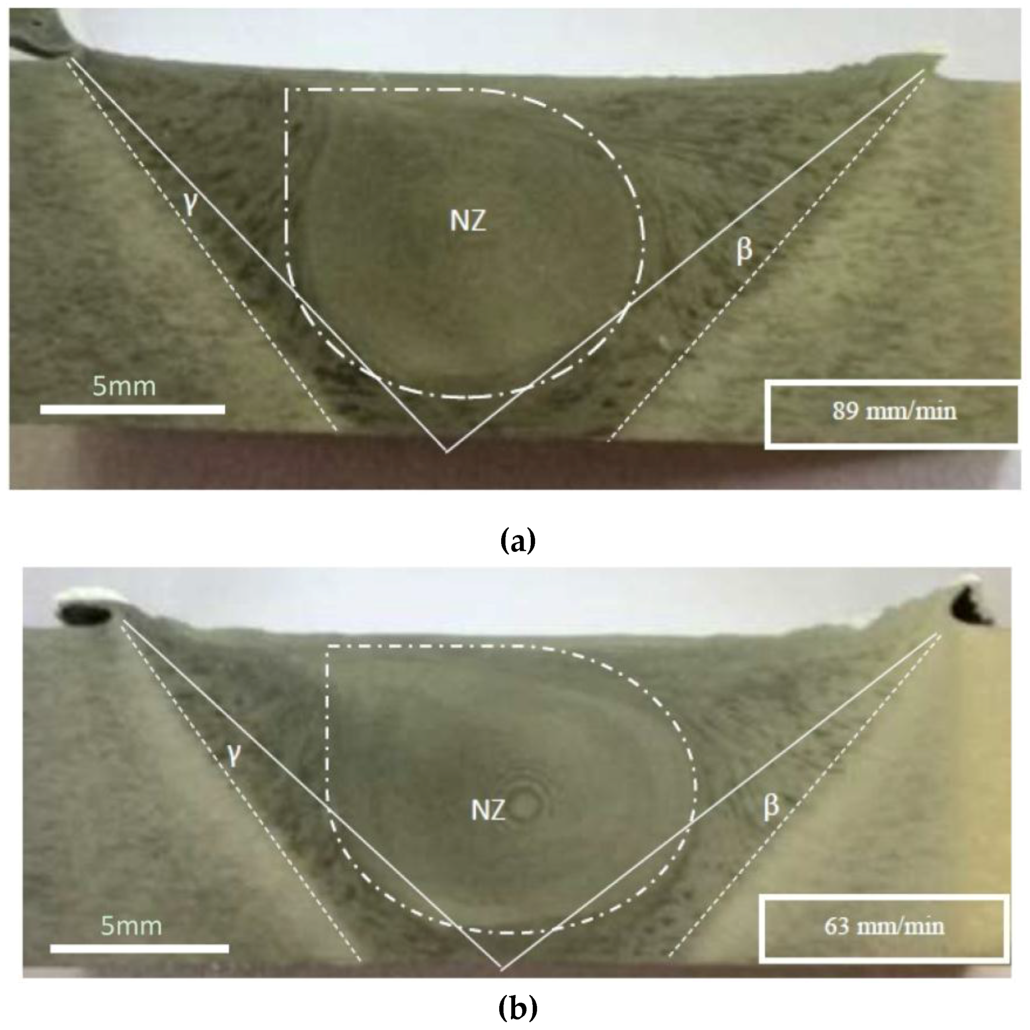
Zhang et al. [23] showed some of related parameters such as pin shape and welding parameters have an important role on the morphology and on the mechanical properties in LHZ. The shape and size of HAZ and TMAZ, which are apparently related to welding parameters and tool, can shift LHZ to right or left (toward base metal or NZ). The initial weld cavity is achieved on the shape of pin when rotating pin moving at a given plunge rate contacts the joint line. In this step, the material flow is influenced by the pin. Furthermore, it can force out the materials from weld cavity. However, the tool shoulder should reflect back the ejected materials into the weld cavity [24,25]. This interaction between pin and shoulder, firstly by sliding and then by sticking, makes a shear surface between weld pool and base metal. This sheared zone is mostly trapezoid-shaped including NZ and TMAZ. When the bigger base is restricted to diameter of shoulder, the size of smaller base can be from a point (triangle) to the same base (rectangle) that is influenced by shape of the pin and welding parameters. Triangle ARC is an area limited between shoulder and pin tip in Figure 5. It is an ideal area for minimizing the sheared area in joint that means lower effect in microstructural and mechanical properties of base metal. Deviation of AC and CR from their theoretical situation to the real location (LHZ) is an indication for changing in different FSW sections. This means that quality of welds with close integration to the HAZ in FSW welding is a function of deviation of AC and CR from their theoretical situation. This deviation is indicated by γ in retreating side and by β in advancing side in Figure 5, whereas Table 4 shows that increase in welding speed can change γ and β adversely.

Figure 5.
Schematic of FSW and affected area by shoulder and pin used in this study.
Table 4.
γ and β deviation for different welding speed.
Increase in welding speed from 63 to 89 mm/min makes γ decrease from 15° to 12°, however the changes in β are inconsiderable (Figure 6), which means that the size of HAZ and TMAZ located around the NZ and γ and β were affected by welding parameters. Hence, the widening of γ and β not only alter the LHZ location but also determine the quality of FSW and make it useable to distinguish the changes in welding parameters [26].

Figure 6.
Cross-section macrostructure of butt joint section AA6061-T6 Al alloy at different welding speeds. (a) 89 mm/min welding speed (b) 63 mm/min welding speed.
Figure 6 also shows the size of NZ influenced by welding speed. It is clear that NZ can be confined through the raise of welding speed.
3.2. Microstructure
In Figure 4, certain regions were created within the joint during FSW. Each of these regions is micro-structurally different than other regions. It should be noted that the heat required for softening the material is generated by frictional heat between the rotating tool (Shoulder), the work pieces (external source of heat) and by plastic deformation of the material as an internal source of heat [9]. Accordingly, the temperature of the generated heat rises to the range of 0.8–0.9 from the melting point of the joint material [9]. Thus, the maximum temperature in the weld region is revealed within the NZ. This temperature creates the severe deformation of the material under the tool welding, so that the transition of the temperature will gradually decrease from the NZ to the base metal. The generation of heterogeneous microstructure within the weld region as opposed to the base metal, can be related to the difference in the thermal gradient between the weld region and the base metal. Based on morphological observations, the variation in the microstructure from the base metal to the centre of the weld region is remarkable. The variation in the microstructure after FSW is an important parameter that has a significant impact on the mechanical properties of welded joints.
The base metal is the part of the weldment that was not metallurgically affected by the welding process. It is located far from the weld. That means its microstructure remained unchanged throughout the entire welding process.
The HAZ is an important part in all fusion and solid state welding of precipitation hardening alloys. The thermal cycle creates a clearly significant effect on the solution of precipitates of alloy during welding process. Indeed, the alteration of structure in the HAZ can be attributed to the induced heat at this region and the cooling rates after FSW. In this case, although some researchers reported a significant grains coarsening in HAZ [20,21,27], it has almost coarse grains but similar to the base metal in our study (Table 5).
Table 5.
Grain size of Nugget Zones (NZs) and Heat Affected Zones (HAZs).
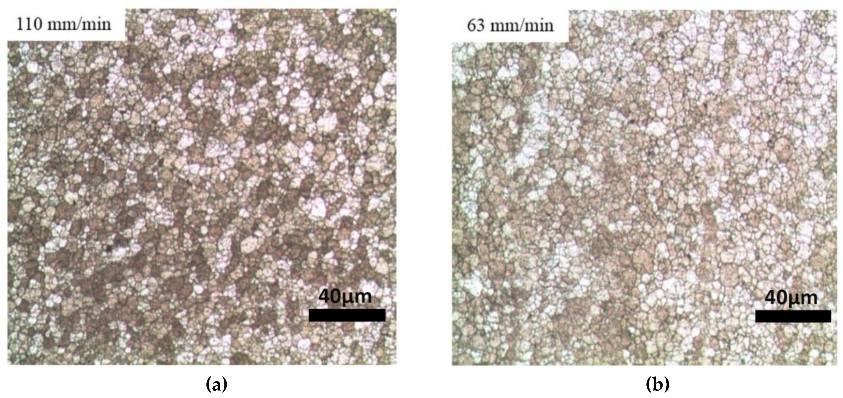
Figure 7 presents the microstructure of HAZs of different welding speed. The extent of HAZ, which shows the range of softening and solution of precipitants, is an important issue. The hardness test indicates this extent.
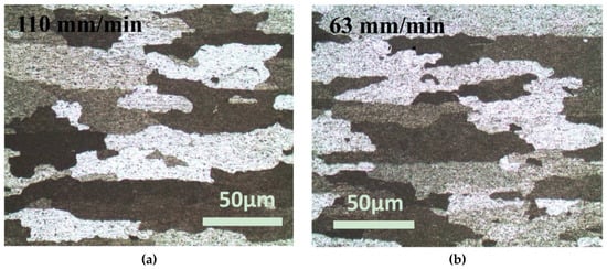
Figure 7.
Optical images of Heat Affected Zones (HAZs) of different welding speed (a) 110 mm/min welding speed (b) 63 mm/min welding speed.
In the NZ, microstructure morphology is identified by dynamically or continuously recrystallized fine equiaxed grains because of the severe deformation as shown in Figure 8, which is caused by the sufficient pin stirring action during welding process. Accordingly, microstructure feature of the NZ is different in terms of size and shape of grain than that of the HAZ and the base metal [9].

Figure 8.
Optical microstructure of Nugget Zone (NZ) in highest (a) and lowest (b) welding speed (a) 110 mm/min welding speed (b) 63 mm/min welding speed.
Grain growth is positively influenced by heat input in weldment. Contrary to rotational speed, welding speed has a reverse effect on generated heat during friction stir welding [18], which means heat input is reduced with increase in welding speed. Conclusively, a lower temperature is contained in the weld nugget zone and a short time is available for grain growth after recrystallization resulting in smaller grain sizes in the NZ of welded joints [9,28].
The image analysis of micrograph was performed and the average grain size of the NZ and the HAZ were determined by ASTM standard E112 [29] using linear intercept method. The values of grain size in the NZ and HAZ at different welding conditions are illustrated in Table 5.
As presented in Table 5, during the HAZ, similar to the NZ, the average grain size decreased with increase of welding speed (although it was little). The average grain size in the HAZ decreased from 133 μm to 128 μm with increase in welding speed from 63 to 110 mm/min.
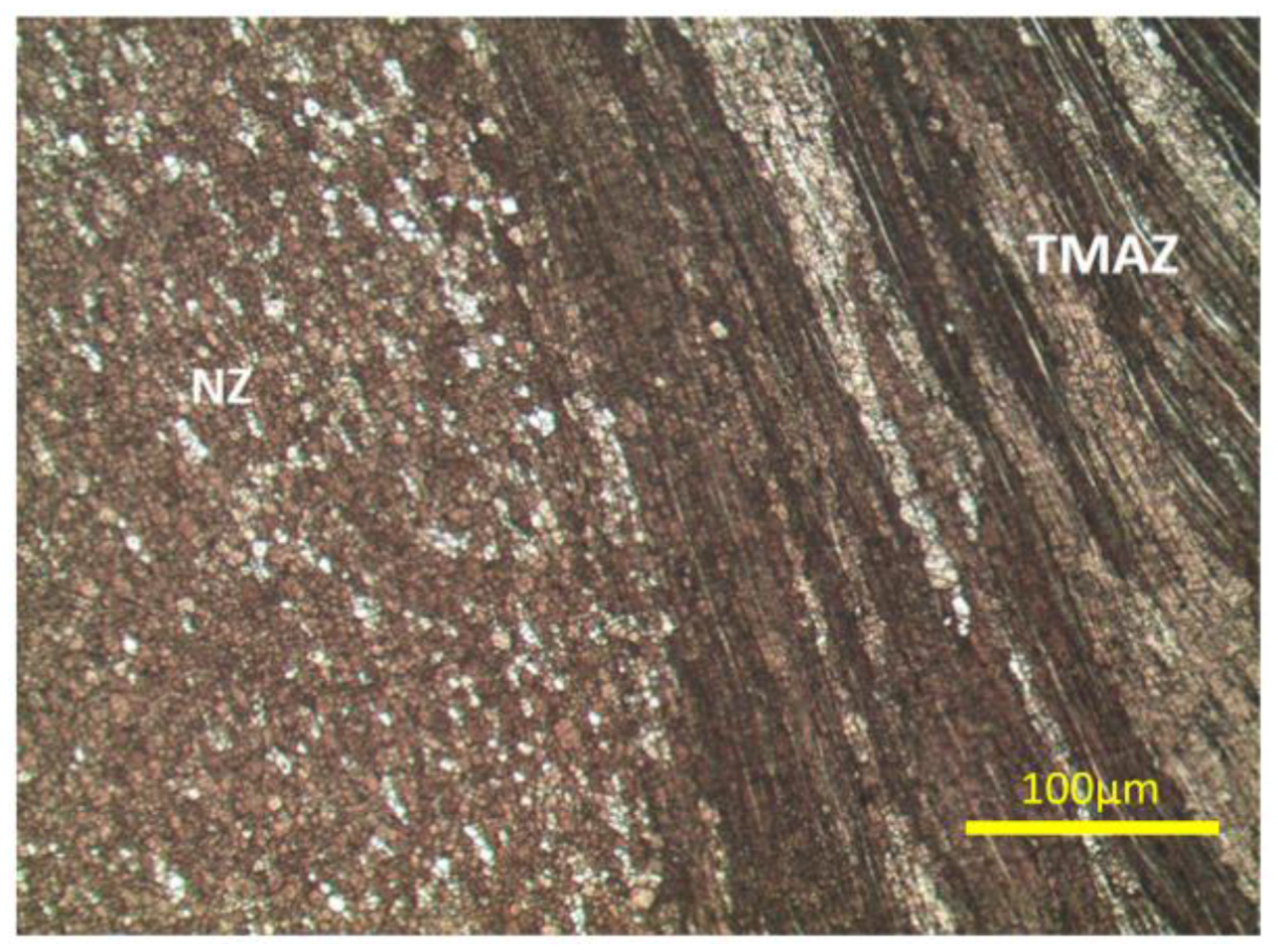
The TMAZ which is located in shearing area receives frictional heat and plastic deformation results by the rotating tool. The elongated grains along the flow line and dynamic recovered grain structure are considered as the TMAZ because the thermal and deformation condition was not enough to create the recrystallized grain structure. In fact, the original grains of base metal were microscopically disappeared in the thermo-mechanically affected zone (TMAZ), and the transient microstructure between the NZ and HAZ was realized. As Figure 9 indicates, it is difficult to find the texture of TMAZ by using optical microscopy and even SEM images.
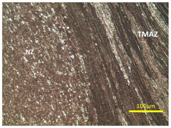
Figure 9.
Optical image of NZ and TMAZ (110 mm/min) 100X.
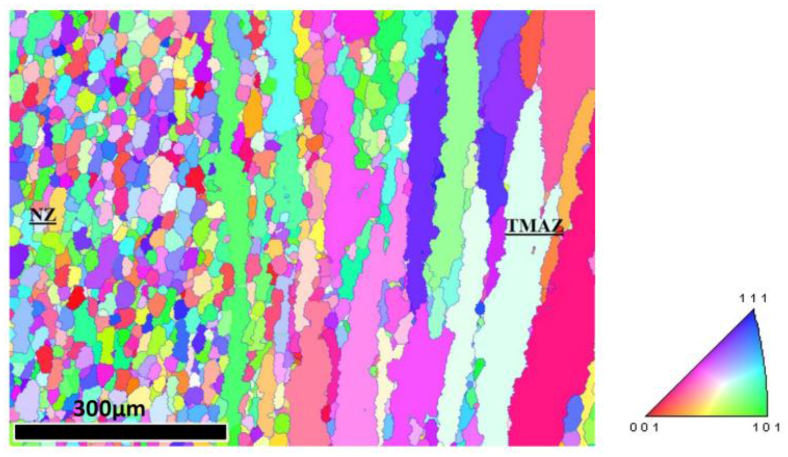
The mobility and establishment of “high-angle grain boundaries” or HAB is in charge of fine microstructure in NZ [30]. According to Brandon [31], a “high-angle boundary” is a boundary with a misorientation higher than 15°. The grains in NZ and TMAZ could not be revealed at the same time of chemical etching because of this difference between high angle grain boundaries in NZ and lower angle grain boundaries in TMAZ. However, EBSD is really useful to settle this problem by providing grain boundary and grain orientation map of different zones in welded joint (Figure 10).
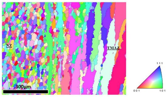
Figure 10.
Grain orientation analyzed by Electron backscatter diffraction (EBSD) of NZ and TMAZ (110 mm/min).
3.3. Hardness Evaluation
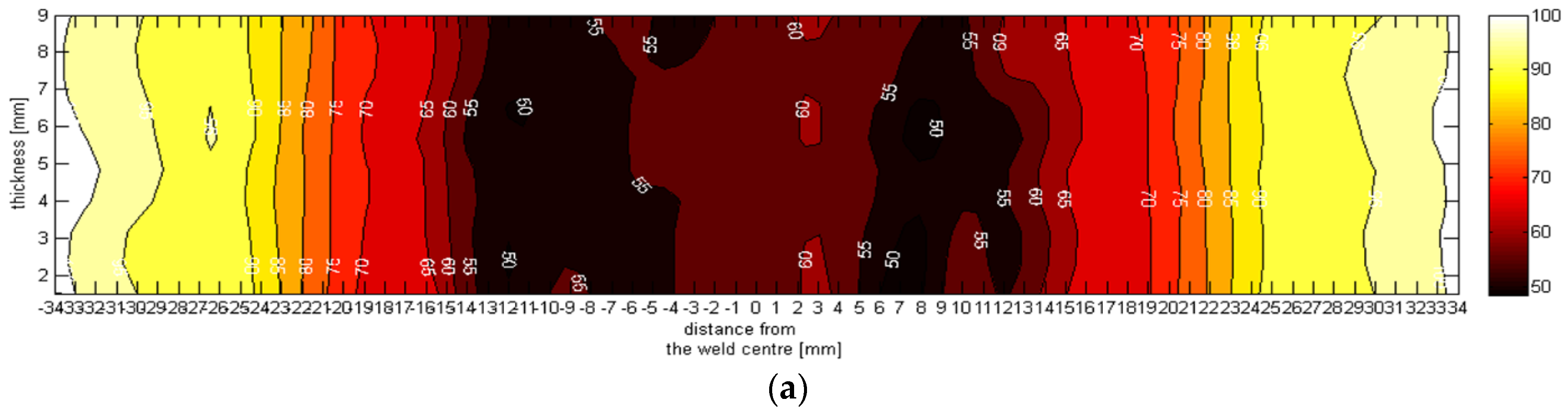
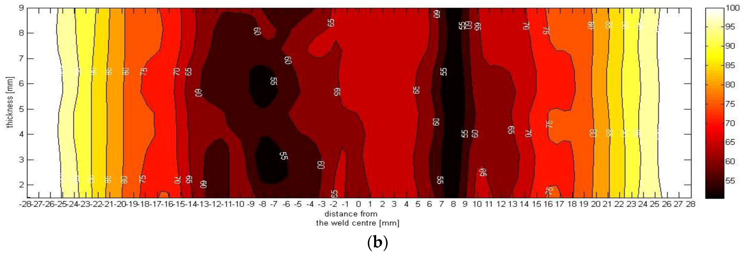
AA6061-T6 is a precipitation hardening alloy. The hardness can be influenced by dissolving precipitates in grains and grain boundaries due to mechanical and thermo mechanical works in NZ and thermal effect (heat input) in HAZ. This is why the weld nugget, TMAZs and HAZs regions have lower values of hardness and strength as compared to parent material [9,28]. The reason that hardness of NZ is higher than HAZ, with respect to both experienced solution of precipitations, should be explained by finer grain size in NZ. Figure 11 presents the effect of welding speed in distribution of hardness. The lowest microhardness values, in 63 mm/min welding speed are obtained close to the RS-TMAZ whiles the LHZ region with a minimum of 50 HV0.5. In the HAZ region, micro hardness value is increased to achieve the base metal when the Vickers hardness is around 110 HV0.5. The difference between the highest and the lowest microhardness value is about 55 %. It is clear that the average microhardness in the weld nugget zone (NZ) has increased from 60.1 to 67.6 HV with the raise of welding speed from 63 to 110 mm/min. Although the microhardness of retreating side is lower than the advancing side, the microhardness curve is almost symmetric around the weld centreline. Contrary to the majority of studies, the retreating side experiences a higher decrease than the advancing side. This phenomenon has been reported in the researches that used clockwise threated pin with counter clockwise rotational speed [28]. It means the retreating side experiences higher plastic strains than the advancing side.
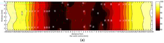

Figure 11.
Hardness mapping at: (a) 63 mm/min; and (b) 110 mm/min.
3.4. Tensile Properties and Fractography
No imperfection was found in macroimage, however over etching of the cross sections in Keller agent accompanied with using optical microscopy in some samples and SEM in others, reveal the discontinuities near the root, as well as, the border of NZ and TMAZ in AD (Figure 12). The EDX mapping analysis indicated the oxide layers in these locations (Figure 13) that confirms the existence of kissing bonds [10,32,33]. It is difficult to measure the actual size of kissing bond due to interruption within (Figure 12c), however our observation says that in the lower welding speed (63 mm/min), the shortest kissing bond was occurred. Nonetheless, it is proven in our tensile test that if the kissing bond does not occur in root or if it is removed from root, the tensile properties cannot be influenced. It can be said that the length or size of remaining kissing bond in weld (not in root) does not affect the ultimate and yield stress. Indeed, the LHZ is more important than kissing bond in tensile test if there is no kissing bond in root of welds.
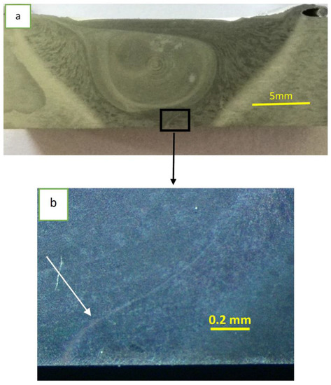
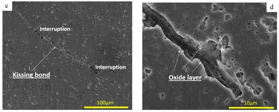
Figure 12.
Kissing bond in 89 mm/min: (a,b) macrograph of kissing bond in root; and (c,d) SEM image of kissing bond.

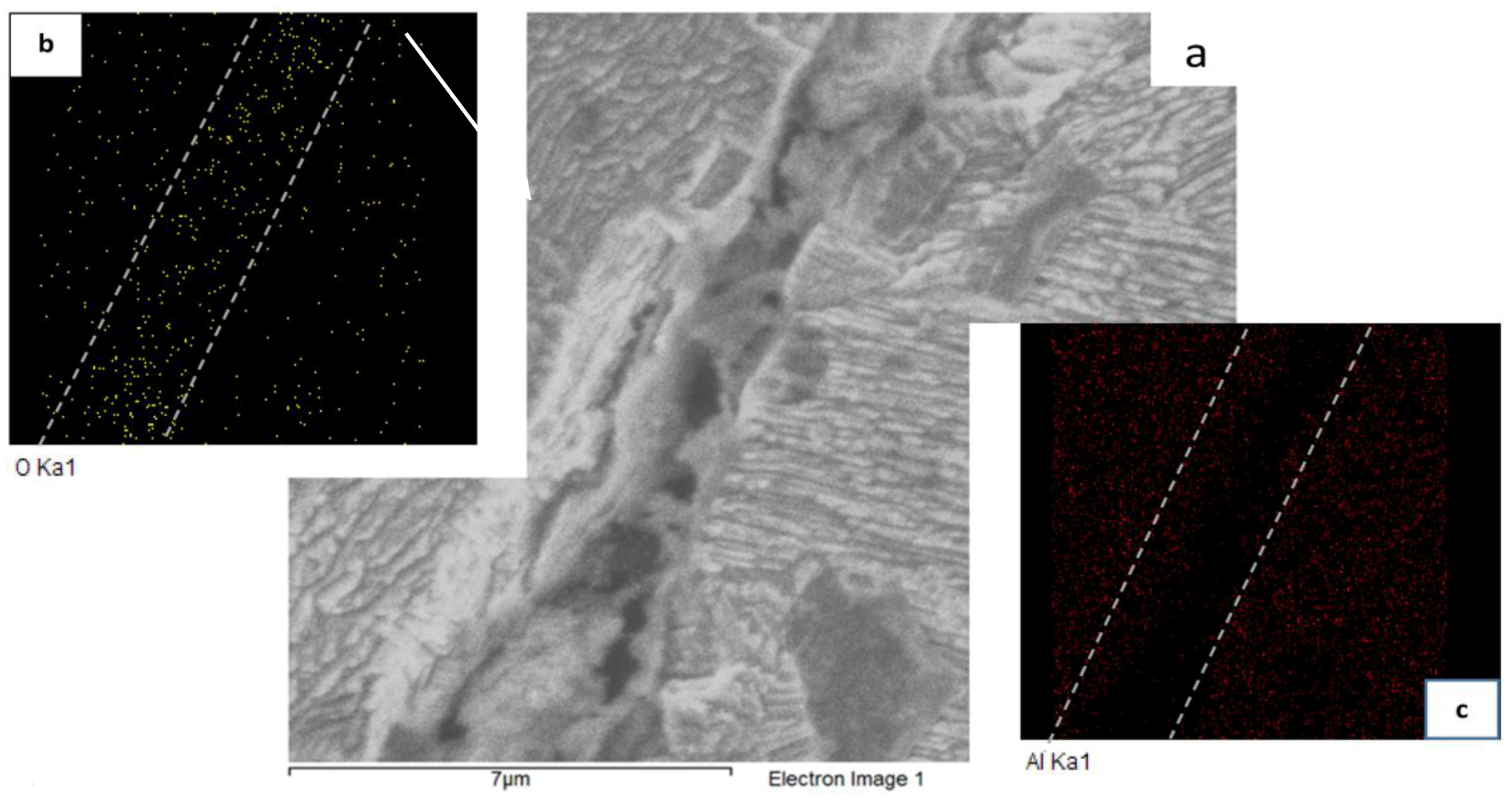
Figure 13.
EDX mapping of oxide layer around kissing bond: (a) SEM image of kissing bond; (b) distribution of oxygen around the kissing bond in yellow color; and (c) distribution of Al around kissing bond in red color.
Because of the probability of kissing bond or any unforeseen discontinuity in line behind the joint (root), as mentioned above, samples would be tested with two conditions:
- (a)
- As-weld
- (b)
- Machined sample (the joints were machined from the root side to remove 0.5 mm of thickness).
For the sample with kissing bond in root, the fracture started from the root and followed the path of kissing bond (almost border of NZ and TMAZ), whereas the fracture location was moved to LHZ of retreating side in all samples after removing the root (Figure 14).
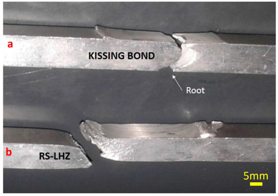
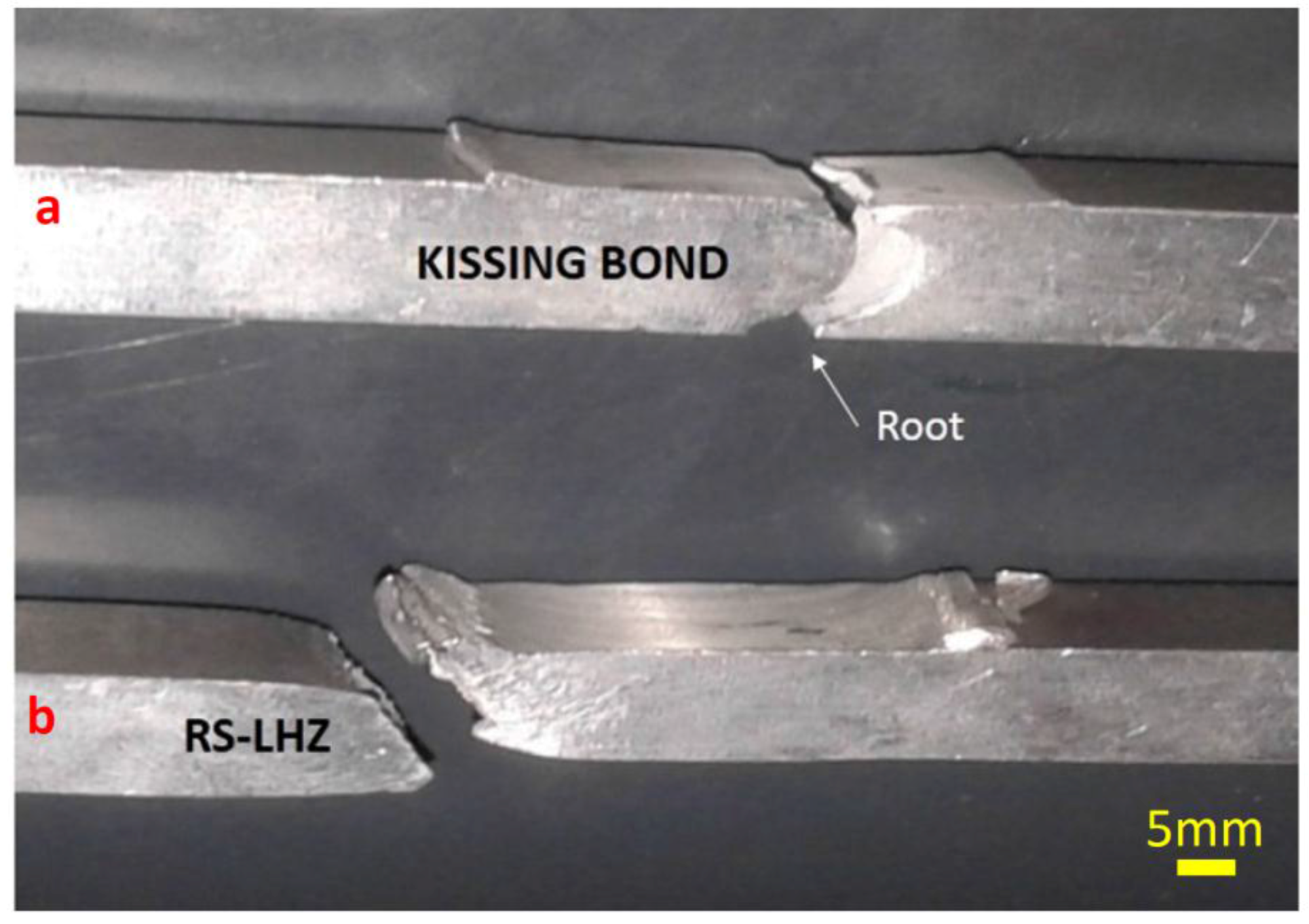
Figure 14.
Fracture location: (a) As-weld; and (b) Machined.
For better comparison, average ultimate tensile strength (UTS) and yield strength of all samples (four samples for each condition) are presented in Table 6 in both two conditions. The results show a significant improvement in tensile properties after removing the root kissing bond.
Table 6.
Mechanical properties obtained by tensile tests (average).
As is clear from the tensile result, by increasing the welding speed, the tensile properties move closer to the base metal (Table 2). Our observation says that, when the kissing bond does not appear in root pass (or removed by machining), the tensile properties may not be influenced by this defect even if it remains disjointed in the weldment.
Fractures’ surface was investigated by SEM. Figure 15 shows the fracture surface of samples that failed from kissing path. The pictures illustrate shallow dimples and mostly sheared cleavage facets showing that brittle fracture occurred. There are non-uniformities in failure surface in Figure 15. The existence of these uneven parallel areas (A) in Figure 15a display the interruption of kissing bonds (Figure 12c) after sample separation from kissing bond path.
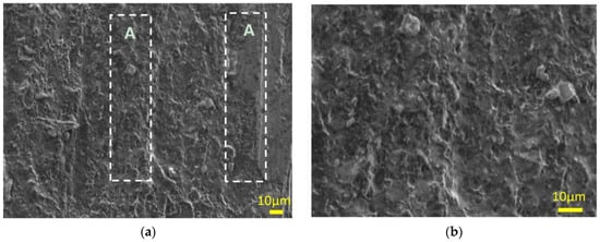
Figure 15.
SEM image from kissing bond location: (a) 500×; and (b) 1000×.
The EDX analysis mostly shows Fe rich component in that area (Figure 16). Niranjani et al. [34] proved that Al/Fe compounds are the most stable among all intermetallic compounds of AA6061-T6, thus Al/Fe compounds are expected to be an effective point in fractures due to the high stability, which can be seen in Figure 16.

Figure 16.
EDX analysis of kissing bond fracture location.
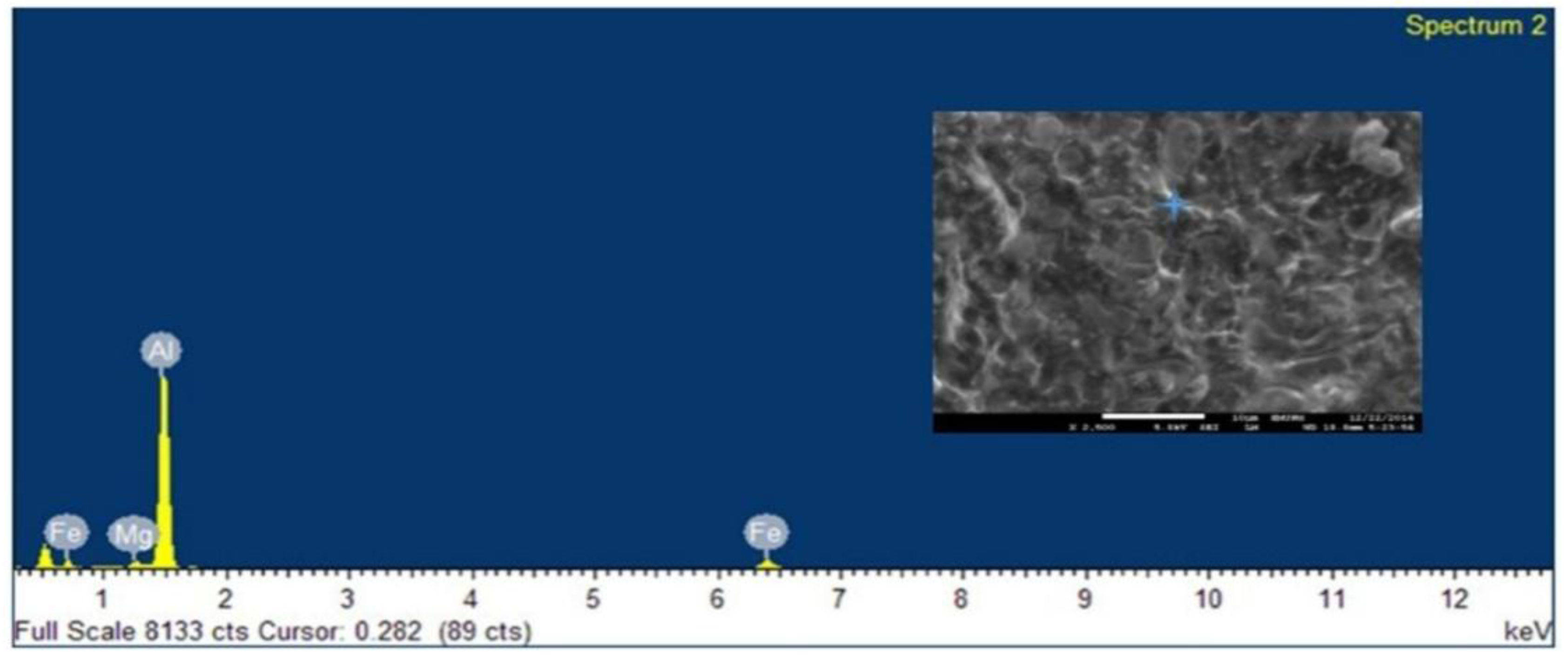
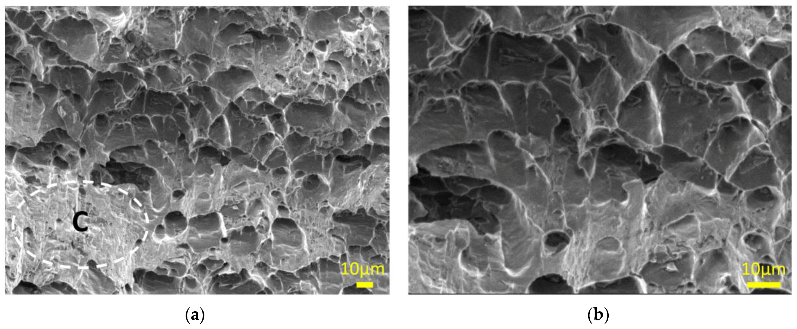
However, Figure 17 shows the fracture morphology in the samples that the fracture path was located in LHZ. Although there are relatively deep dimples in the fracture surface, there are some cleavage areas (C in Figure 17a) representatives of mix ductile-brittle fracture.
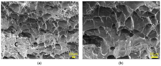
Figure 17.
SEM image from RS-LHZ location: (a) 500×; and (b) 1000×.
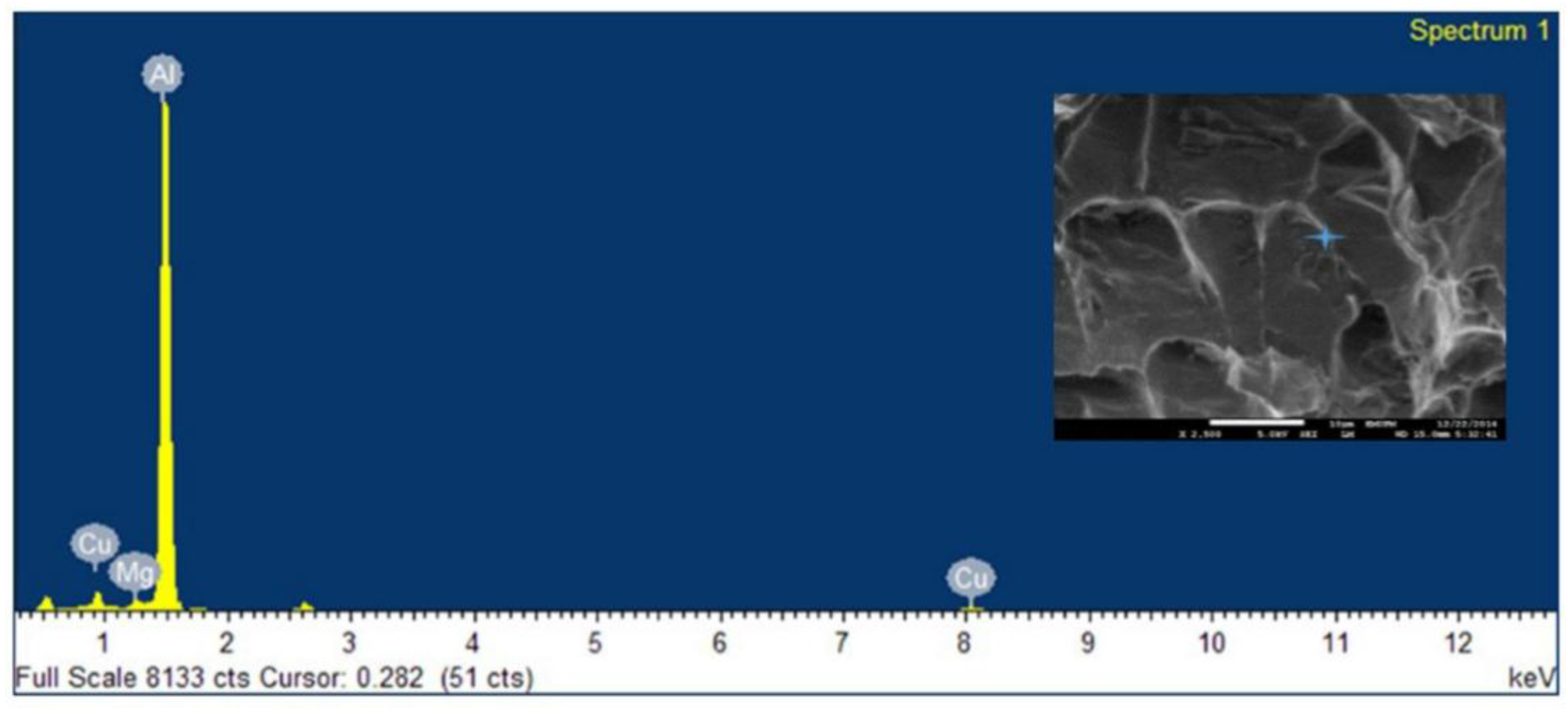
Because of the lower temperature in LHZ compared to NZ [28], and no mechanical work in LHZ, the existence of intermetallic Si/Al, Fe/Al and Cr/Cu/Al is acceptable (Figure 18).

Figure 18.
EDX analysis of RS-LHZ fracture location.
4. Conclusion
AA6061-T6 aluminum alloy has been welded by friction stir in butt joint. The effect of welding speed on macrostructure of joint, texture of the NZ and TMAZ zones, hardness and tensile properties were investigated.
- (a)
- The dimension and size of weld zone (including NZ, HAZ and TMAZ) is well related to the welding parameters (welding speed). Increase in welding speed caused less deviation for LHZ, which means decreases in γ and β.
- (b)
- With increasing welding speed, the grain size of weld nugget zone decreased. In the heat affected zone (HAZ), the grain size was decreased by increasing welding speed, although in all samples, the grain size of HAZ is a bit bigger than base metal.
- (c)
- Regardless of the process conditions and parameters, all friction stir welded butt joints had a softened region including NZ, TMAZ and HAZs as compared to base metal. This can be influenced by dissolving precipitates in grains and grain boundaries due to mechanical and thermo mechanical works in NZ, TMAZ and thermal effect (heat input) in HAZ. However, the hardness in NZ is higher than TMAZ. The reason should be explained by finer grain size in NZ. The hardness in NZ, TMAZ and HAZ showed an increasing trend by increase in welding speed.
- (d)
- Kissing bond was introduced in weld at all three different welding speeds, which could be Al2O3. The total length of kissing bond was increased in higher welding speed. However, the appearance of kissing bond in root of joint had destructive effect in tensile test. An improvement was achieved in ultimate tensile strength by removing the kissing bond. This amount was 25% at 110 mm/min welding speed (159 MPa/119 MPa). Fracture location was located in RS-LHZ for all samples after removal of kissing bond from root.
Acknowledgments
The authors are most grateful to the University Putra Malaysia for the financial support extended to this research work. We greatly appreciate the valuable advices of Saman Azhari in recent revising of this paper.
Author Contributions
Firouz Fadaeifard designed the experimental procedure. Khamirul Amin Matori supervised the entire research work. Firouz Fadaeifard, Liyana Zolkarnaia and Aliff Zairie Bin Abdul Rahim performed the experiment. Khamirul Amin Matori and Sidek Abd Aziz provided valuable scientific advices for the entire experiment. Firouz Fdaeifard analyzed data and wrote the paper while the final manuscript was revised by Khamirul Amin Matori and Sidek Abd Aziz.
Conflicts of Interest
The authors declare no conflict of interest.
References
- Hufnagel, W. Key to Aluminum Alloys; Aluminium-Verlag: Dusseldorf, Germany, 1999. [Google Scholar]
- Ramachandran, T.R. Advances in Aluminum Processing and its Automotive Application; the Indian Institute of Metals, Pune Chapter: Pune, India, 2006; pp. 28–32. [Google Scholar]
- Gharavi, F.; Matori, K.A.; Yunus, R.; Othman, N.I.; Fadaeifard, F. Corrosion evaluation of friction stir welded lap joints of AA6061-T6 aluminum alloy. Trans. Nonferr. Met. Soc. China 2016, 26, 684–696. [Google Scholar] [CrossRef]
- Török, I.; Juhász, K.; Meilinger, Á.; Balogh, A. Main characteristics of fusion and pressure welding of aluminium alloys. Prod. Process. Syst. 2012, 5, 91–106. [Google Scholar]
- Thomas, W.M.; Nicholas, E.D.; Needham, J.C.; Murch, M.G.; Temple Smith, P.; Dawes, C.J. Improvements Relating to Friction Welding. International Patent Application No. PCT/GB92/02203 Publication No. WO19930109935 A1, 6 December 1991. [Google Scholar]
- Liu, G.; Murr, L.E.; Niou, C.S.; McClure, J.C. Microstructural Aspects of the Friction Stir Welding of 6061-T6 Aluminum. Scr. Mater. 1997, 37, 355–361. [Google Scholar] [CrossRef]
- ASM International. ASM Handbook: Welding, Brazing and Soldering; ASM International: Materials Park, OH, USA, 1993; pp. 297–324. [Google Scholar]
- Knipström, K.E.; Pekkari, B. Friction stir welding process goes commercial. Weld. J. 1997, 76, 55–57. [Google Scholar]
- Mishra, R.S.; Ma, Z.Y. Friction stir welding and processing. Mater. Sci. Eng. Rep. 2005, 50, 1–78. [Google Scholar] [CrossRef]
- Leonard, A.J.; Lockyer, S.A. Flaws in friction stir welds. In Proceedings of 4th International Symposium on Friction Stir Welding, Park City, UT, USA, 14 May 2003.
- Lacki, P.; Kucharczyk, Z.; Śliwa, R.E.; Gałaczyński, T. Effect of tool shape on temperature field in friction stir spot welding. Arch. Metal. Mater. 2013, 58, 595–599. [Google Scholar] [CrossRef]
- Thomas, W.M.; Staines, D.G.; Norris, I.M.; de Frias, R. Friction stir welding tools and developments. Weld. World 2003, 47, 10–17. [Google Scholar] [CrossRef]
- Carlone, P.; Palazzo, G.S. Influence of process parameters on microstructure and mechanical properties in AA2024-T3 friction stir welding. Metallogr. Microstruct. Anal. 2013, 1, 213–222. [Google Scholar] [CrossRef]
- Velotti, C.; Astarita, A.; Buonadonna, P.; Dionoro, G.; Langella, A.; Paradiso, V.; Prisco, U.; Scherillo, F.; Squillace, A.; Tronci, A. FSW of AA 2139 plates: Influence of the temper state on the mechanical properties. Key Eng. Mater. 2013, 554–557, 1065–1074. [Google Scholar] [CrossRef]
- Integrated, M. Mechanical and Metallurgical Characterization of Friction Stir Welding AA6351. Ph.D. Thesis, Mewar University, Rajasthan, India, 2015. [Google Scholar]
- Dawes, C.J.; Threadgill, P.L.; Spurgin, E.J.R.; Staines, D.G. Development of the new friction stir technique for welding aluminium. TWI GSP 1995, 5651, 1994–1997. [Google Scholar]
- ISO 4136:2012. Destructive Tests on Welds in Metallic Materials—Transverse Tensile Test. Available online: http://www.iso.org/iso/catalogue_detail.htm?csnumber=62317 (accessed on 30 November 2012).
- Sedmak, A.; Kumar, R.; Chattopadhyaya, S.; Hloch, S.; Tadić, S.; Djurdjević, A.; Čeković, I.; Dončeva, E. Heat input effect of friction stir welding on aluminum alloy AA 6061-T6 welded joint. Therm. Sci. 2016, 20, 637–641. [Google Scholar] [CrossRef]
- Kumbhar, N.T.; Bhanumurthy, K. Friction stir welding of Al 6061 alloy. Asian J. Exp. Sci. 2008, 22, 63–74. [Google Scholar]
- Arbegast, W.J. Modeling friction stir joining as a metalworking process. In Proceedings of the Hot Deformation of Aluminum Alloys III, Warrendale, PA, USA, 2003; pp. 313–327.
- Arbegast, W.J. Using process forces as a statistical process control tool for friction stir welds. In Proceedings of the 2005 TMS Annual Meeting: Friction Stir Welding and Processing III, San Francisco, California, USA, February 2005; pp. 193–204.
- Colligan, K. Material flow behavior during friction welding of aluminum. Weld J. 1999, 75, 229–237. [Google Scholar]
- Zhang, Y.N.; Cao, X.; Larose, S.; Wanjara, P. Review of tools for friction stir welding and processing. Can. Metall. Quart. 2012, 51, 250–261. [Google Scholar] [CrossRef]
- Kumar, K.; Kailas, S.V. The role of friction stir welding tool on material flow and weld formation. Mater. Sci. Eng. A 2008, 485, 367–374. [Google Scholar] [CrossRef]
- Frigaard, Ø.; Grong, Ø.; Midling, O.T. A process model for friction stir welding of age hardening aluminum alloys. Metall. Mater. Trans. A 2001, 32, 1189–1200. [Google Scholar] [CrossRef]
- Fadaeifard, F.; Matori, K.A.; Toozandehjani, M.; Daud, A.R.; Ariffin, M.K.A.M.; Othman, N.K.; Gharavi, F.; Ramzani, A.H.; Ostovan, F. Influence of rotational speed on mechanical properties of friction stir lap welded 6061-T6 Al alloy. Trans. Nonferr. Met. Soc. China 2014, 24, 1004–1011. [Google Scholar] [CrossRef]
- Elangovan, K.; Balasubramanian, V.; Babu, S. Predicting tensile strength of friction stir welded AA6061 aluminum alloy joints by a mathematical model. Mater. Des. 2009, 30, 188–193. [Google Scholar] [CrossRef]
- Nandan, R.; DebRoy, T.; Bhadeshia, H.K.D.H. Recent advances in friction-stir welding–process, weldment structure and properties. Prog. Mater. Sci. 2008, 53, 980–1023. [Google Scholar] [CrossRef]
- ASTM E112-96(2004), Standard Test Methods for Determining Average Grain Size, ASTM International, West Conshohocken, PA, USA, 2004. Available online: https://www.astm.org/DATABASE.CART/HISTORICAL/E112-96R04.htm (accessed on 11 January 2004).
- Doherty, R.; Hughes, D.; Humphreys, F.; Jonas, J.; Jensen, D.J.; Kassner, M. Current issues in recrystallization: A review. Mater. Sci. Eng. A 1997, 238, 219–274. [Google Scholar] [CrossRef]
- Brandon, D. The structure of high-angle grain boundaries. Acta Metall. 1966, 14, 1479–1484. [Google Scholar] [CrossRef]
- Chen, Z.W.; Pasang, T.; Qi, Y. Shear flow and formation of Nugget zone during friction stir welding of aluminium alloy 5083-O. Mater. Sci. Eng. A 2008, 474, 312–326. [Google Scholar] [CrossRef]
- Kadlec, M.; Růžek, R.; Nováková, L. Mechanical behavior of AA 7475 friction stir welds with the kissing bond defect. Int. J. Fatigue 2015, 74, 7–19. [Google Scholar] [CrossRef]
- Niranjani, V.L.; Kumar, K.H.; Sarma, V.S. Development of high strength Al-Mg-Si AA6061 alloy through cold rolling and ageing. Mater. Sci. Eng. A 2009, 515, 169–174. [Google Scholar] [CrossRef]


© 2017 by the authors. Licensee MDPI, Basel, Switzerland. This article is an open access article distributed under the terms and conditions of the Creative Commons Attribution (CC BY) license ( http://creativecommons.org/licenses/by/4.0/).