


Abstract
In aerospace manufacturing, laser welding of TC4/TA18 dissimilar titanium alloys in bottom-locking configurations is essential for lightweight design, yet the residual stress behavior of such joints remains insufficiently understood. This study systematically examines the influence of laser power on residual stress distribution in laser-welded TC4/TA18 bottom-locking tubular joints. Welded specimens were fabricated at three distinct laser power levels (600 W, 800 W, and 1000 W). Experimental characterization included macroscopic morphology analysis and residual stress measurement using the blind-hole drilling method, among other techniques. Concurrently, a three-dimensional thermo-elastic-plastic finite element model was established based on ABAQUS 2022 to simulate the transient temperature field and stress–strain field during the welding process. The results indicate that due to the differences in thermophysical properties between the two titanium alloys and the wall thickness effect, both the temperature field and residual stress distribution of the TC4/TA18 dissimilar titanium alloy bottom-locking joints exhibit significant asymmetry. Laser power exerts a selective influence on the residual stress field: within the parameter range of this study, increasing laser power can significantly reduce the peak hoop stress of TA18 thin-walled tubes and TC4 thick-walled tubes, as well as the peak axial stress of TC4 thick-walled tubes, while remarkably increasing the peak axial stress of TA18 thin-walled tubes. The numerical simulation results are in good agreement with the experimental data, verifying that the established finite element model is an effective tool for predicting welding outcomes.
1. Introduction
The aerospace industry’s growing demand for lightweight and highly reliable structures has driven the extensive adoption of multi-material components in engineering practice [1]. These components integrate the respective advantages of metals and composite materials. In this context, dissimilar titanium alloy welding has emerged as a critical technology in aerospace manufacturing. By precisely combining the performance benefits of different titanium alloys, this approach enables the dual objectives of weight reduction and performance optimization in structural components [2,3,4,5]. Among these, the dissimilar welding between high-strength TC4 (Ti-6Al-4V) and high-ductility TA18 (Ti-3Al-2.5V) titanium alloys is particularly representative. Such joints can provide integrated fluid transmission components (e.g., aircraft piping systems) with a balanced combination of strength and formability [5]. To meet these application needs, the bottom-locking joint has been widely adopted in aero-engine and airframe structures, owing to its self-aligning nature, ease of assembly, and reliable sealing performance [6,7]. Laser welding, characterized by its high energy density, low heat input, narrow heat-affected zone, and minimal weld deformation, enables reliable joining of dissimilar materials with significantly different physical and thermomechanical properties. As a result, it has emerged as a core process for precision welding applications, gradually replacing conventional arc welding and attracting considerable industrial attention [8,9,10]. However, the rapid heating and cooling cycles inherent to laser welding often induce substantial residual stresses within the joint, which can significantly affect structural integrity, fatigue performance, and long-term service reliability [11]. Therefore, a thorough understanding and effective control of residual stress in laser-welded dissimilar titanium bottom-locking joints are crucial for ensuring the safety and durability of aerospace components and for advancing the application of laser welding technology in this field.
Currently, researchers primarily focus on the microstructure and mechanical properties of laser-welded joints between dissimilar titanium alloys (e.g., TC4/TA15, TC4/CP-Ti, Ti-2/TC4, etc.) to achieve welded joints with minimal or no defects [5]. However, studies on residual stresses in laser welding of both similar and dissimilar titanium alloys remain relatively limited. Zhang et al. [12] used the hole-drilling method to compare the residual stress distributions in laser-welded and tungsten inert gas (TIG)-welded joints of thin-sheet titanium alloys. They found that the residual stress distribution in laser-welded joints was similar in morphology to that in conventional fusion welding processes, but the affected zone was significantly narrower, and the residual stress in the heat-affected zone was about 100 MPa lower than in TIG-welded joints. Junaid et al. [13] compared the residual stress distribution and deformation in Ti–5Al–2.5Sn alloy under laser welding, TIG welding, and electron beam welding. Their study indicated that laser-welded specimens exhibited lower tensile residual stress and deformation than electron beam-welded specimens, while TIG-welded specimens showed the highest values. Xie et al. [14] investigated the residual stress distribution in 50 mm thick Ti-6Al-4V plates joined by electron beam welding using finite element analysis and the contour method. Their results revealed a narrow yet steep stress gradient in the joint, with the peak tensile stress in the interior exceeding the yield strength of the base material. Frankel et al. [15] studied residual stresses in linear friction welding of Ti–6Al–4V and Ti–6Al–2Sn–4Zr–2Mo, while Xie et al. [16] examined residual stresses in linear friction-welded joints of α + β and β-Ti17 alloys. Both studies observed an asymmetric distribution of residual stresses in linear friction-welded joints of dissimilar titanium alloys. Overall, existing research has predominantly concentrated on residual stresses in flat-plate titanium alloy joints. In contrast, residual stresses in laser-welded dissimilar titanium alloys, particularly in lock-step joint configurations, have rarely been reported to date.
This study focuses on the welding of TC4/TA18 dissimilar titanium alloy tubes with a bottom-locking structure. Welding experiments were conducted at three laser power levels (600 W, 800 W, and 1000 W), and the macroscopic morphology of the weld seam as well as the residual stress of the joint were systematically analyzed. In addition, a three-dimensional thermo-elasto-plastic finite element model was established using ABAQUS 2022 software to simulate the dynamic evolution of the transient temperature and stress–strain fields during the laser welding process. The research aims to clarify the influence of laser power on the residual stress distribution in dissimilar titanium alloy bottom-locking joints. The findings are expected to provide practical guidance for optimizing laser welding parameters and ensuring the in-service safety of complex aerospace components.
2. Experimental Procedure
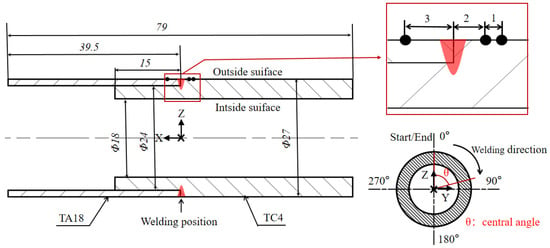
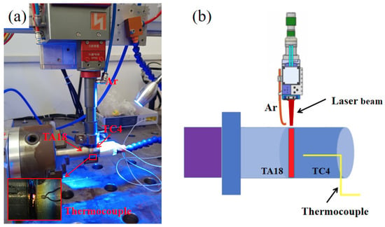
This study employed two titanium alloy tubes, TC4 (Ti-6Al-4V) and TA18 (Ti-3Al-2.5V), as the base materials, whose nominal chemical compositions are summarized in Table 1 [17]. Both tubes were machined into a bottom-locking joint configuration, with a schematic diagram of the specific structure and geometric dimensions provided in Figure 1. The TA18 tube had an outer diameter of 27 mm, a wall thickness of 1.5 mm, and a length of 39.5 mm, while the TC4 tube exhibited corresponding dimensions of 27 mm in outer diameter, 4.5 mm in wall thickness, and 54.5 mm in length. It is noteworthy that one end of the TC4 tube was machined with a locating shoulder, measuring 15 mm in length and 1.5 mm in height, to ensure precise alignment during the assembly of the two tubes. The welding was conducted at the interface of the locating shoulders, with the welding direction and center angle defined in Figure 1. To avoid both insufficient penetration from low heat input and excessive ablation or melt pool collapse from high heat input, three dissimilar titanium alloy bottom-locking joints were fabricated using an IPG YLS-6000 fiber laser system (IPG Photonics, Oxford, MA, USA) following extensive preliminary trials and literature review. In this study, laser power levels of 600 W, 800 W, and 1000 W were respectively applied while maintaining a constant welding speed of 20 mm/min, ultimately achieving good penetration [18]. Figure 2 shows an actual view of laser welding and a schematic diagram of the process.
Table 1.
Nominal chemical composition of the base materials (wt.%).
Figure 1.
Geometric dimensions (Unit: mm) of the dissimilar titanium alloy bottom-locking joints, definition of central angle, and locations of temperature measurements.
Figure 2.
(a) actual view of the laser welding; (b) Schematic of the laser welding.
Experimental characterization primarily included thermal cycle measurement and residual stress evaluation. The welding thermal cycles were recorded using K-type thermocouples on the outer surface of the tubes where the central angle θ was 180°, with the thermocouple locations shown in Figure 1. Residual stress testing was performed using the blind-hole drilling method with strain gauge rosettes [19], and principal stresses were calculated in accordance with ASTM E837 standard [20]. Macroscopic morphologies of the joints were prepared using Kroll’s reagent (3% hydrofluoric acid + 30% nitric acid + 67% distilled water), and the macroscopic morphologies were captured using a Leica DM4M optical microscope (Leica, Wetzlar, Germany).
3. Numerical Analysis
3.1. Finite Element Models
A coupled thermo-mechanical analysis of laser welding for dissimilar titanium alloy tubes was performed using a thermo-elastic-plastic finite element method within the ABAQUS code. The simulation was performed in two sequential steps. The thermal analysis, which was first conducted independently to solve the heat conduction problem, provided the transient temperature field. This temperature history was then applied as a thermal load in the subsequent mechanical analysis.
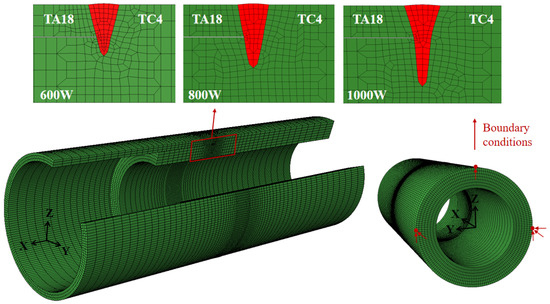
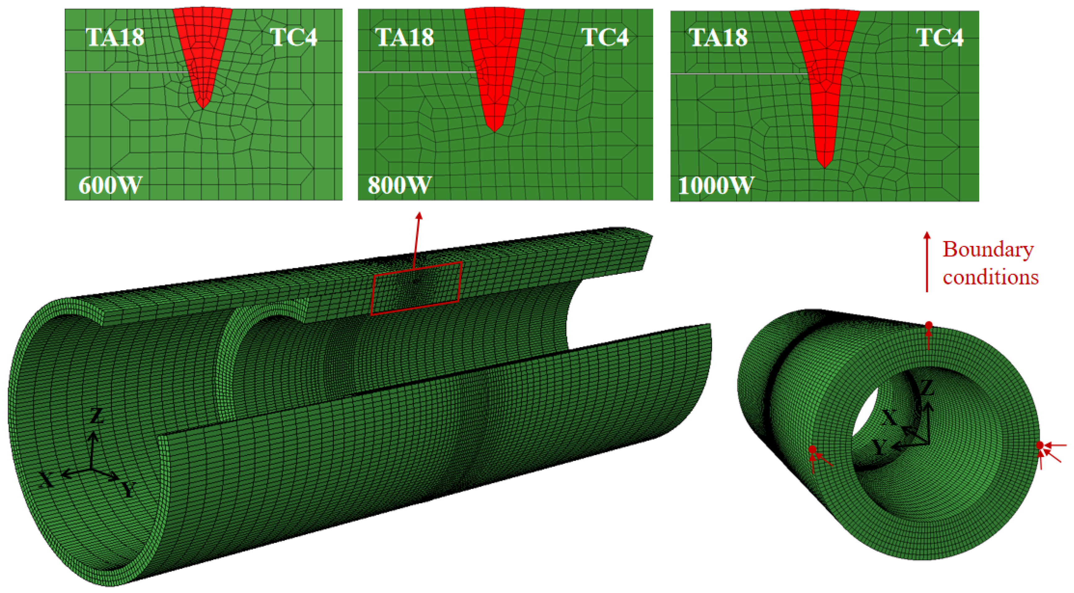
Three finite element models were developed based on the actual geometry of the dissimilar titanium alloy tube joints. The mesh in the weld region was constructed according to the macroscopic morphology observed in experiments, as shown in Figure 3. To balance computational accuracy and efficiency, a refined mesh was applied in the weld and adjacent areas, while a coarser mesh was used in regions farther away from the weld. The finite element models corresponding to the three laser power conditions (600 W, 800 W, and 1000 W) had the following specifications: 97,740 elements and 116,280 nodes for 600 W; 128,160 elements and 110,520 nodes for 800 W; and 127,440 elements and 109,440 nodes for 1000 W. The temperature field and stress–strain field simulations employed DC3D8 and C3D8I element types, respectively [21].
Figure 3.
Finite element models and boundary conditions.
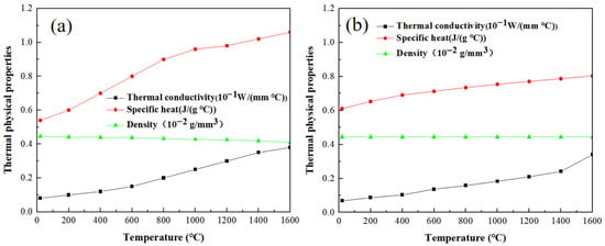
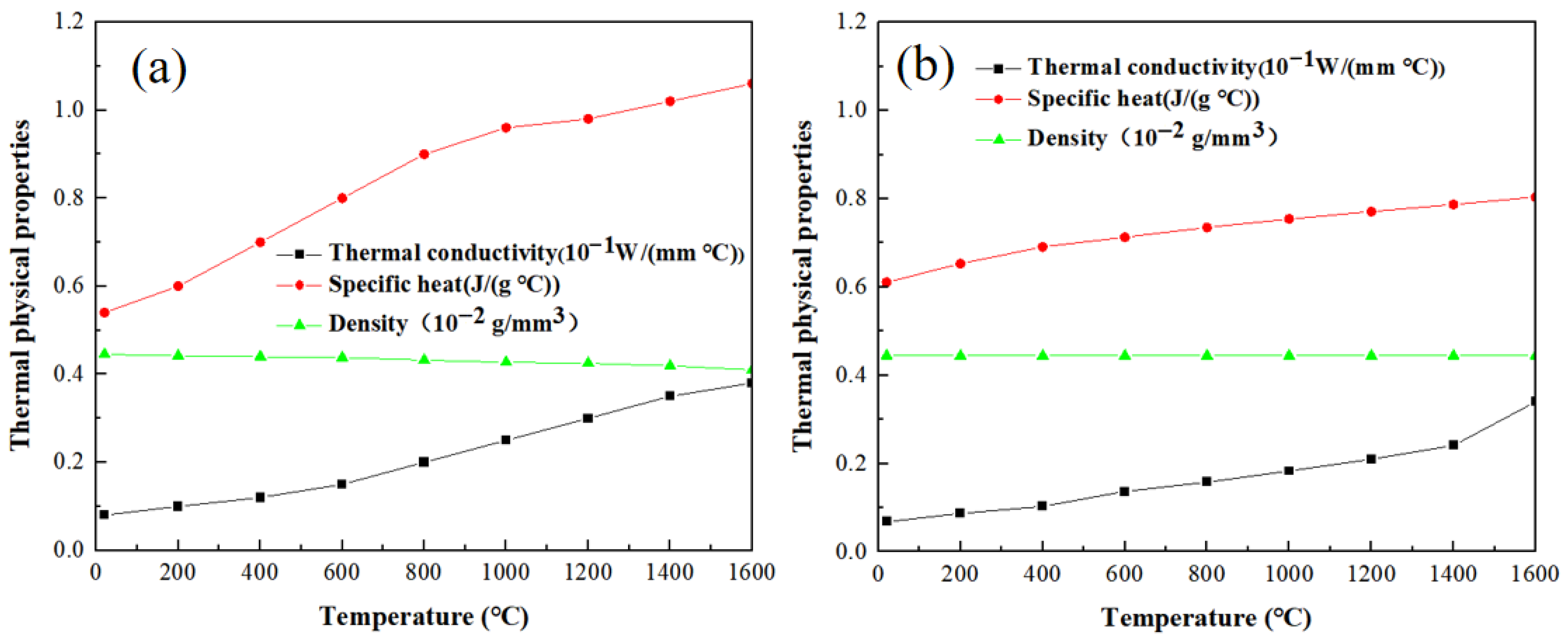
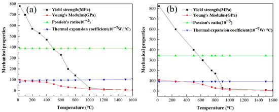
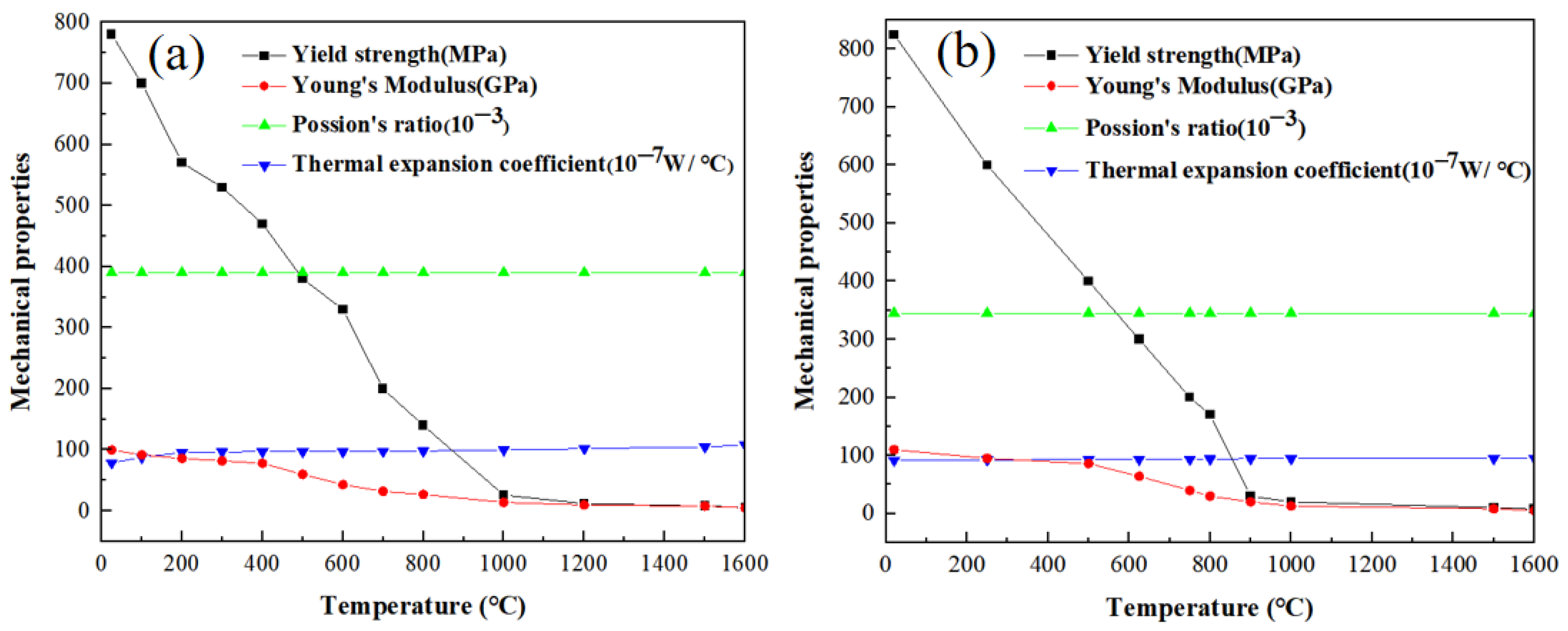
The thermal and mechanical analyses incorporated temperature-dependent properties—including thermal conductivity, specific heat capacity, and density for the thermal analysis, as well as Young’s modulus, Poisson’s ratio, thermal expansion coefficient, and yield strength for the mechanical analysis—with the variations of these properties with temperature for both TA18 and TC4 alloys presented in Figure 4 and Figure 5, respectively [22,23]. The performance parameters of the weld metal are determined by weighted calculation using the arithmetic mean method, based on the proportion of TA18 and TC4 alloys in the weld metal.
Figure 4.
Temperature-dependent thermophysical properties: (a) TA18; (b) TC4.
Figure 5.
Temperature-dependent mechanical properties: (a) TA18; (b) TC4.
3.2. Simulation Cases
To investigate the influence of laser power on the residual stress distribution in laser-welded TA18/TC4 dissimilar titanium alloy bottom-locking tubes, three cases were designed. Specifically, Case A corresponds to a laser power of 600 W, while Cases B and C have welding powers of 800 W and 1000 W, respectively.
3.3. Thermal Analysis
The governing equation for transient heat conduction analysis in the temperature field simulation is given by:
where ρ represents the density, c denotes the specific heat capacity, T stands for the instantaneous temperature, t is the time, ∇ is the spatial gradient operator, q is the heat flux vector, and Q represents the heating rate of the internal heat source.
A three-dimensional Gaussian conical heat source model was employed to simulate the laser welding process, with its heat flux distribution defined by the following equations:
where re stands for the radius of upper surface, while ri represents the radius of bottom surface; ze and zi represent the Z coordinates of upper and bottom surfaces, respectively. Q2 denotes laser welding power, and η2 stands for the efficiency of the laser welding. The heat flux load was implemented in the ABAQUS software platform through a user-defined DFLUX subroutine developed in FORTRAN 2016.
Additionally, the convective and radiative heat losses were characterized based on Newton’s law of cooling and the Stefan-Boltzmann law, respectively, and are calculated using Equations (5) and (6).
where hc stands for the heat transfer coefficient; Ts represents the surface temperature of the workpiece; T0 denotes the ambient temperature taken as 20 °C. σ denotes the Stefan–Boltzmann constant; ε is the emissivity, which takes the value of 0.8.
3.4. Mechanical Analysis
The mechanical analysis utilized the same finite element model as the thermal analysis, with modifications made only to the element type and boundary conditions. The restraint conditions are indicated by arrows in Figure 3. This boundary condition accurately replicates the actual experimental constraint scenario. By applying symmetric constraints to three nodes on the bottom surface of the tubular structure, rigid body motion is effectively suppressed [24]. In this study, the strain changes induced by creep and solid-state phase transformations during the welding process are neglected. The strain composition at a material point can thus be expressed as follows:
where represents the elastic strain, denotes the plastic strain, is the thermal strain. The elastic and plastic strains followed the isotropic Hooke’s law and the Von Mises criterion, respectively.
4. Results and Discussion
4.1. Temperature Field
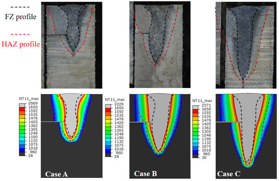
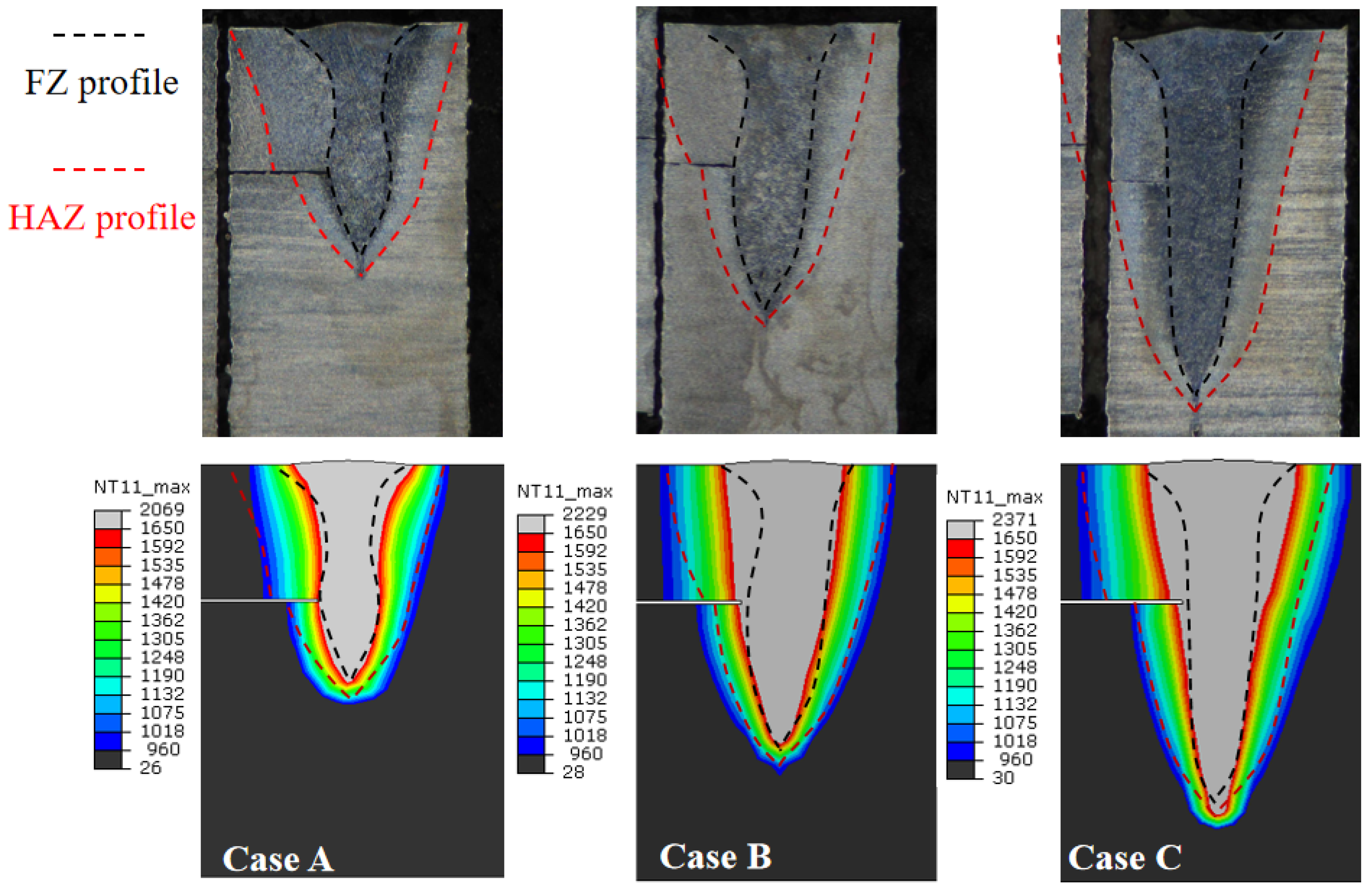
Figure 6 compares the simulated and experimentally measured weld morphology at the 180° cross-section of dissimilar titanium alloy bottom-locking joints under three different laser power settings. The gray area indicates the fusion zone (FZ) (peak temperature > 1650 °C), while the surrounding region with temperatures ranging from 960 °C to 1650 °C corresponds to the heat-affected zone (HAZ). The simulated weld pool morphology under all three conditions shows excellent agreement with experimental results, validating the effectiveness of the established heat source model and related parameters. Both experimental and simulation results collectively demonstrate that as the laser power increases, the weld penetration depth grows significantly from 2.5 mm to 3.1 mm and then to 3.8 mm, showing a clear increasing trend. In contrast, the weld width only expands slightly from 0.7 mm to 0.8 mm and then to 0.9 mm, with relatively limited variation. Further analysis reveals that the temperature distribution in the dissimilar titanium alloy welded joints exhibits distinct asymmetric characteristics under all three conditions. Due to the combined effects of differences in thermophysical properties between the dissimilar materials and the bottom-locking structure, the width of the heat-affected zone on the TA18 titanium alloy side is approximately twice that on the TC4 titanium alloy side.
Figure 6.
Macroscopic morphologies of the bottom-locking structures and peak temperature distributions at the 180° cross-section.
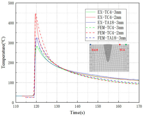
Figure 7 compares the simulated and measured thermal cycle histories at characteristic points for Case B. The simulated curves show excellent agreement with the experimental data in terms of both peak temperature and cooling rate. Both experimental and simulation results indicate that at the same distance (3 mm) from the weld center, the peak temperature on the TA18 titanium alloy side is 50 °C higher than that on the TC4 titanium alloy side. This temperature difference is attributed to two main factors: first, TA18 titanium alloy has higher thermal conductivity, leading to more rapid heat transfer toward the TA18 titanium alloy side during welding; second, the bottom-locking structure results in a smaller thermal mass volume in the TA18 titanium alloy region due to its thinner wall thickness. Compared to the TC4 titanium alloy side with thicker walls, heat dissipation in the TA18 region is slower, ultimately causing more concentrated temperature rise in this area.
Figure 7.
Thermal cycle at the outer surface of the 180° cross-section for Case B.
As shown in Figure 6 and Figure 7, with increasing laser power, the weld penetration of the dissimilar alloy joints increases markedly, whereas the weld width grows only slightly. Due to the combined effects of material properties and joint geometry, the heat dissipation rates on the TA18 and TC4 sides differ significantly. Specifically, the TA18 side exhibits slower heat dissipation owing to its higher thermal conductivity and smaller thermal mass. Consequently, this leads to a clearly asymmetric temperature distribution in the welded joint. In detail, at equal distances from the weld centerline, the peak temperature is higher on the TA18 side than on the TC4 side, and the HAZ width on the TA18 side is approximately twice that on the TC4 side.
4.2. Residual Stress Distribution
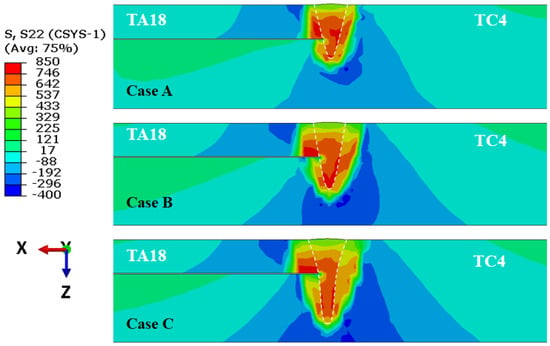
In this section, the influence of laser power on the residual stress distribution in laser-welded bottom-locking TA18/TC4 dissimilar titanium alloy tubes is discussed. Figure 8 shows the hoop stress distribution contours at the 180°cross-section for Cases A, B, and C. The results indicate that the hoop stress distribution follows consistent patterns across all three cases, each exhibiting significant asymmetric characteristics: the FZ and adjacent regions are dominated by high tensile stresses, while compressive stresses develop in areas farther from the FZ to achieve overall stress balance. It is noteworthy that the peak hoop tensile stress in all cases exceeds the yield strengths of both TA18 and TC4 base metals. A comparison of the three cases reveals that as laser power increases, the high-tensile-stress-affected zone in the joint expands, while the peak tensile stress decreases accordingly. This phenomenon occurs because welding residual stress depends mainly on the joint’s peak temperature and constraint conditions. The increase in heat input enlarges the high-temperature region in the TA18/TC4 welded joint while reducing the constraint stiffness, ultimately leading to an expansion of the high tensile stress zone and a reduction in the peak tensile stress [25].
Figure 8.
Hoop stress distribution contours at the 180° cross-section.
An interesting observation from this figure is that although the yield strength of TA18 titanium alloy (780 MPa) is lower than that of TC4 titanium alloy (825 MPa), the TA18 side exhibits a higher peak tensile stress. This behavior is closely related to the bottom-locking structure. Due to the thinner wall thickness on the TA18 side compared to the TC4 side, the cooling rate of TA18 is relatively slower, as confirmed by the thermal cycle results shown in Figure 7. During the cooling process, the TC4 side cools down earlier and establishes constraint conditions, imposing stronger hoop constraints on the still-cooling TA18 side, which consequently results in higher residual hoop stresses.
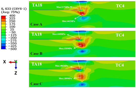
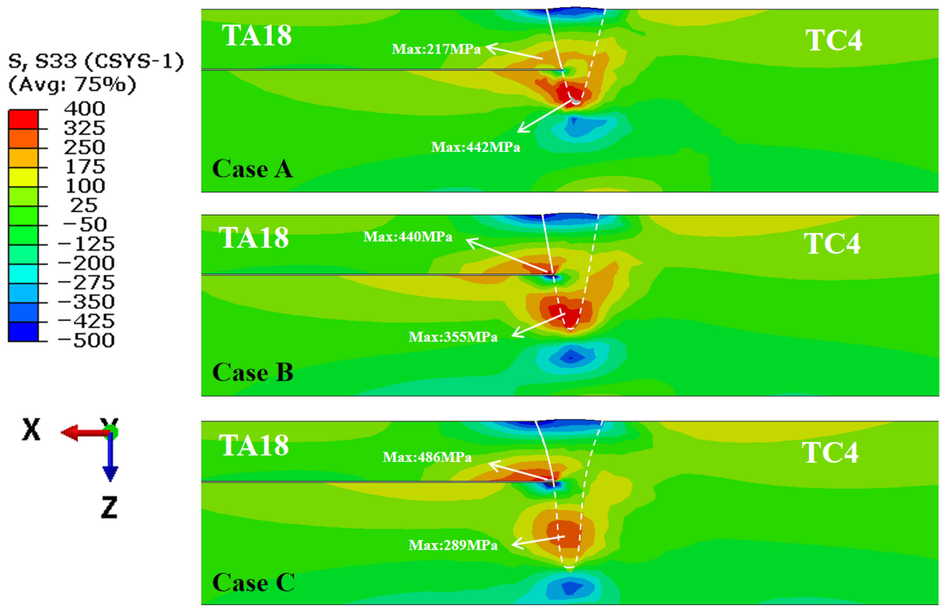
Figure 9 presents the axial stress distribution contours at the 180° cross-section for the three cases (A, B, and C). The axial stress distribution in all cases exhibits significant asymmetric characteristics. For clarity, the welded joint is described separately for the TA18 and TC4 sides. On the TA18 titanium alloy side, high tensile stresses are concentrated in the lower surface region near the FZ, while high compressive stresses are distributed in the upper surface region of the FZ. As the laser power increases, the high tensile stress zone near the lower surface of the FZ gradually expands, and the peak tensile stress increases sequentially from 217 MPa to 444 MPa and 486 MPa. This trend is primarily attributed to the fact that the weld penetration depth on the TA18 side exceeds the plate thickness under all three power levels, resulting in minimal differences in constraint strength on this side. However, the increased heat input leads to greater transverse contraction, which in turn expands the axial tensile stress zone and raises its magnitude on the lower surface of the TA18 side. On the TC4 titanium alloy side, high tensile stresses are mainly observed in the lower part of the FZ and the upper surface of the joint. As the laser power increases, the penetration depth on the TC4 side gradually deepens, and the high-stress zone shifts downward accordingly. Meanwhile, the peak tensile stress decreases progressively from 442 MPa to 355 MPa and 289 MPa. This is mainly because the increase in welding heat input reduces the constraint strength on the TC4 titanium alloy side, thereby lowering the peak axial stress.
Figure 9.
Axial stress distribution contours at the 180° cross-section.
The axial and hoop residual stress contour maps reveal a distinctly asymmetric distribution in the dissimilar titanium alloy bottom-locking joint. For hoop stress, a high tensile stress concentration appears in the fusion zone (FZ) and surrounding areas, while compressive stress develops farther from the FZ to maintain overall equilibrium. Notably, the peak hoop stress is higher on the TA18 side than on the TC4 side, despite TA18’s lower yield strength. Axial stress also differs between the alloys: on the TA18 side, high tensile stress is concentrated on the lower surface near the FZ, while on the TC18 side it is located at the lower part of the FZ and on the upper surface of the joint. The influence of laser power also differs significantly between hoop and axial stress. With increasing laser power, hoop stress shows an expansion of the high tensile zone accompanied by a decrease in peak magnitude. In contrast, for axial stress, the TA18 side exhibits both expansion of the high tensile zone and a marked rise in peak stress, while the TC4 side shows a downward shift of the high-stress region and a gradual reduction in peak stress.
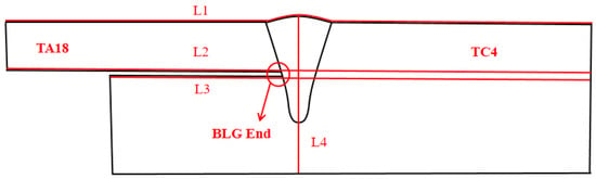
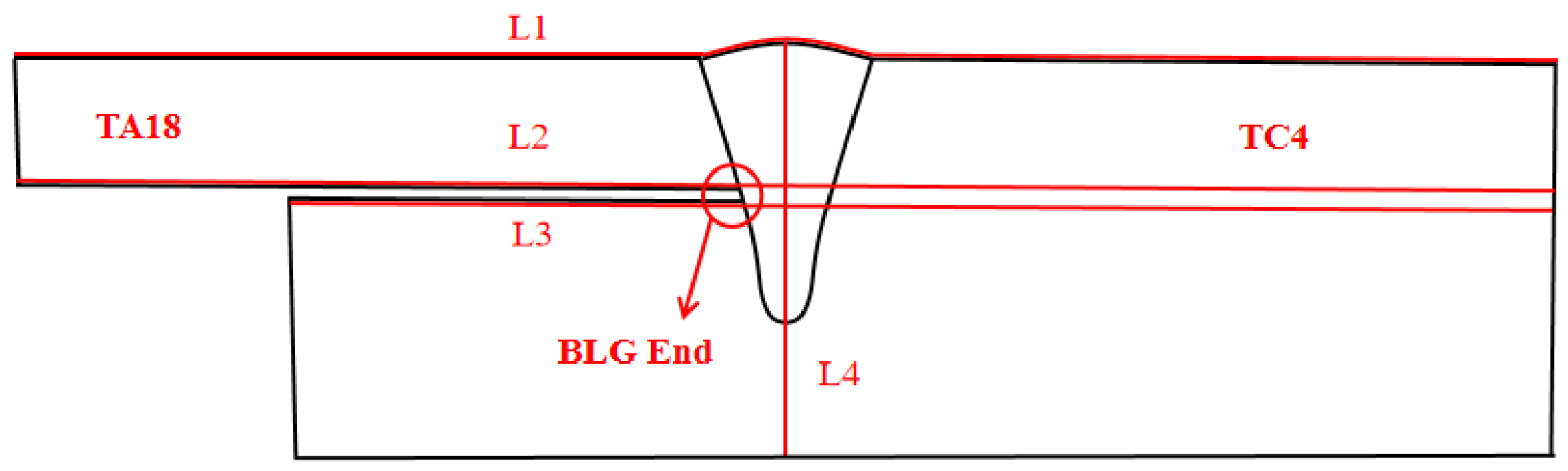
To quantitatively investigate the effect of laser power on the residual stress distribution in laser-welded TC4/TA18 dissimilar titanium alloy tubes with a bottom-locking configuration, this study compares the residual stress distribution characteristics along Paths L1, L2, L3, and L4 at the 180° cross-section. The end of the gap in the bottom-locking joint (BLG End) is a typical characteristic region of the bottom-locking welded joint. Here, the gap formed by the mating of the two tubes directly adjoins the weld, making it a critical zone with high stress concentration and one of the key focus areas of this study. Both the path of this cross-section and the schematic of the BLG End are illustrated in Figure 10.
Figure 10.
Schematic of cross-sectional path and BLG End.
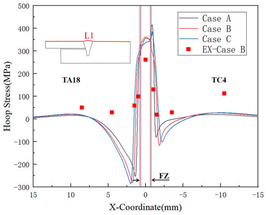
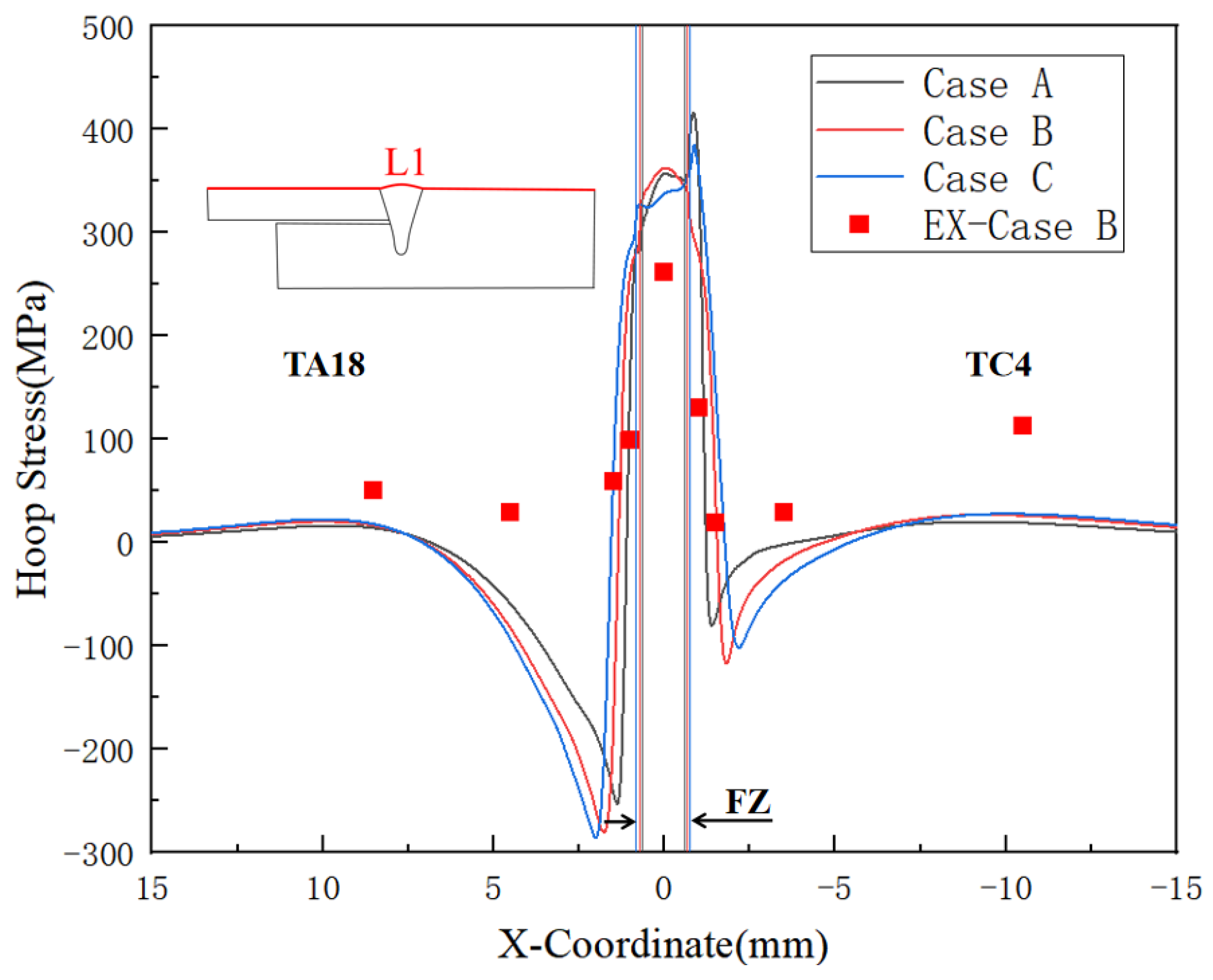
Figure 11 quantitatively compares the hoop residual stress distribution characteristics along Path L1 under three laser welding conditions. As shown in the figure, the stress distribution patterns of the three cases are consistent: a high tensile stress state is observed near the FZ and HAZ. As the distance from the HAZ increases, the stress attenuates rapidly and transitions to compressive stress, eventually approaching a low-stress level in the region far from the weld. Meanwhile, the distribution range of high tensile stress expands with the increase in heat input. This distribution trend shows certain similarities to findings reported in earlier studies [26,27,28]. It should be noted, however, that the present work specifically addresses dissimilar titanium alloy bottom-locking joints, in which the stress field displays a markedly asymmetric distribution. This asymmetry constitutes the most significant distinction between the findings reported here and those of prior research. Under the three cases, the peak hoop tensile stress along Path L1 is far lower than the yield strength of the material, with specific values as follows: 416 MPa for Case A, 363 MPa for Case B, and 384 MPa for Case C. In addition, the simulation results of Case B are in good agreement with the experimental data, which also verifies the reliability of the established numerical method.
Figure 11.
Hoop residual stress distributions along Path L1.
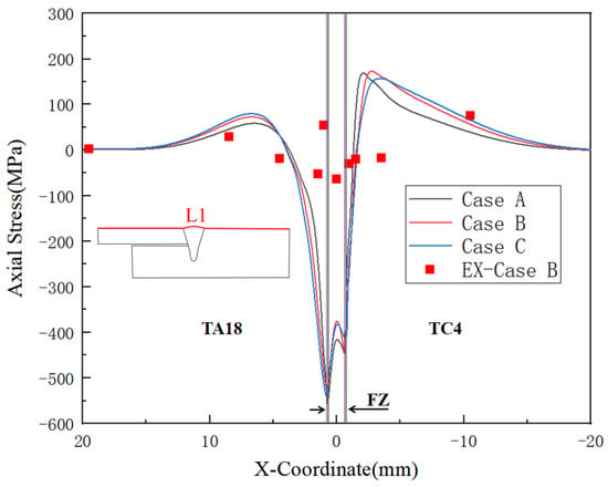
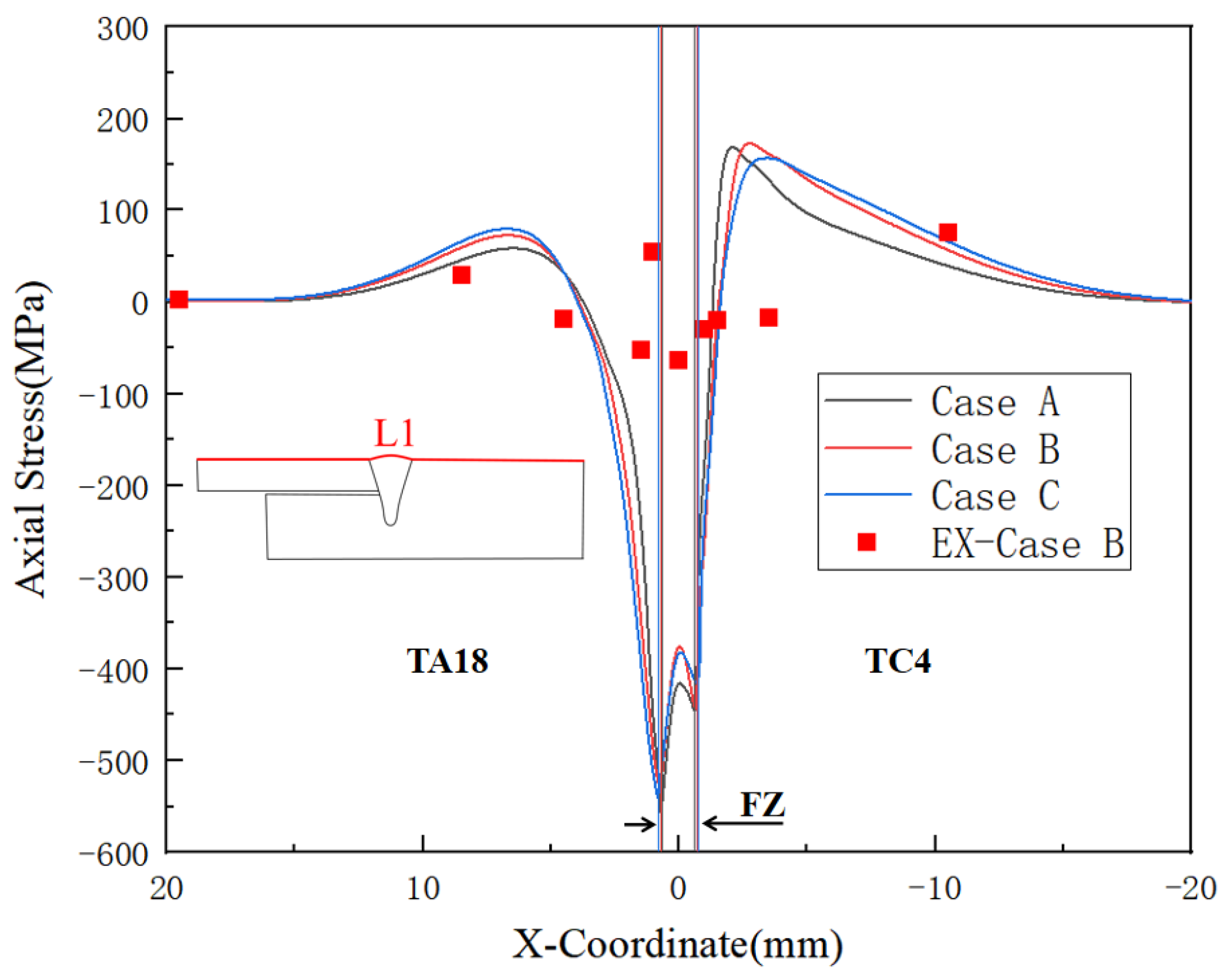
Figure 12 quantitatively compares the axial residual stress distribution along Path L1 under three laser welding conditions. As shown in the figure, the stress distribution patterns of the three cases are highly similar: the axial tensile stress level is relatively low for all cases, while relatively high axial compressive stress generally exists near the FZ and HAZ—a characteristic that is particularly prominent on the TA18 titanium alloy side. This distribution pattern aligns with the typical stress distribution observed on the outer surface of circular tubes, which is characterized by relatively high compressive stresses in the weld zone and an overall M-shaped profile [26,27,28,29,30,31]. Comparing the peak compressive stresses of the three cases, it can be seen that the laser power has a slight effect on the peak axial residual compressive stress along Path L1. Specifically, the peak compressive stress of Case A is −558 MPa, Case B is −553 MPa, and Case C is −540 MPa. In addition, by comparing the experimental and simulated values of axial residual stress for Case B, the two are in good agreement, which further verifies the reliability of the numerical model.
Figure 12.
Axial residual stress distributions along Path L1.
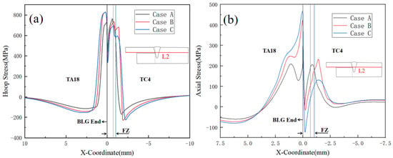
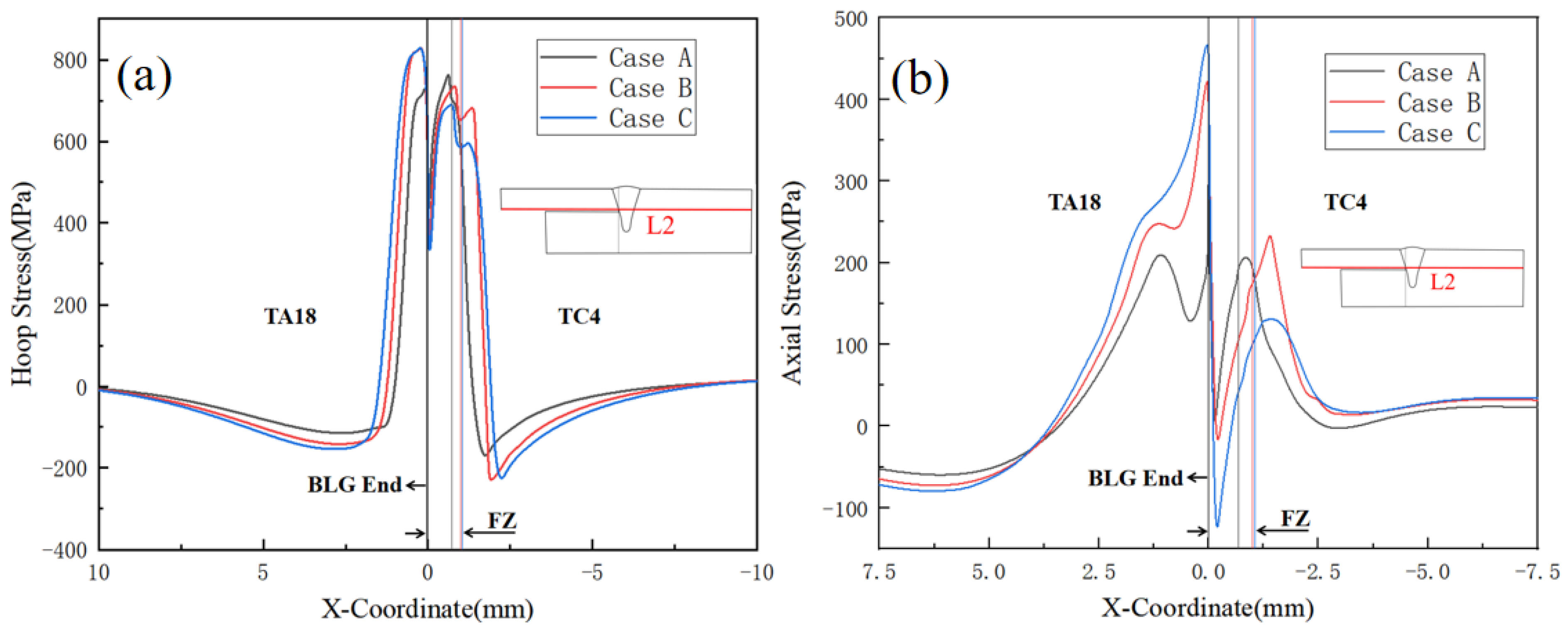
Figure 13a presents the hoop stress distribution characteristics along Path L2 under three laser welding conditions. As shown in the figure, significant stress fluctuation is observed in the BLG End region for all three cases, forming a typical V-shaped stress trough, where the stress level on the TA18 titanium alloy side and in the FZ zone is higher than that on the TC4 titanium alloy side. By analyzing the evolution law of the three curves, it can be clearly confirmed that with the increase in heat input, the peak stress on the TA18 titanium alloy side exhibits a continuous upward trend, and the peak tensile stresses of Cases B and C are nearly 100 MPa higher than that of Case A. In contrast, the peak stress on the TC4 titanium alloy side shows a gradual decreasing characteristic as the heat input increases. The specific values are as follows: the peak stress of Case A is 763 MPa, Case B decreases to 732 MPa, and Case C further reduces to 687 MPa. Furthermore, with the increase in heat input, the distribution range of the high-stress zone in the joint expands synchronously.
Figure 13.
Residual stress distributions along Path L2: (a) Hoop residual stress; (b) Axial residual stress.
Figure 13b illustrates the axial stress distribution law along Path L2 under three laser welding conditions. As can be seen from the curve distribution characteristics, the axial stress distribution exhibits a significant asymmetric feature, and laser power has a remarkable influence on the axial stress distribution along Path L2. Severe stress fluctuation occurs in the BLG End region, where the peak tensile stress on the TA18 titanium alloy side is nearly twice that on the TC4 titanium alloy side. From the perspective of stress evolution trend, the peak axial tensile stress on the TA18 titanium alloy side shows a substantial increase with the rise in welding power: the peak stress of Case A is 293 MPa, while those of Cases B and C reach 420 MPa and 466 MPa, respectively. In contrast, within the FZ zone, the peak tensile stress demonstrates a decreasing trend with the increase in welding power.
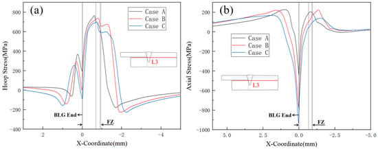
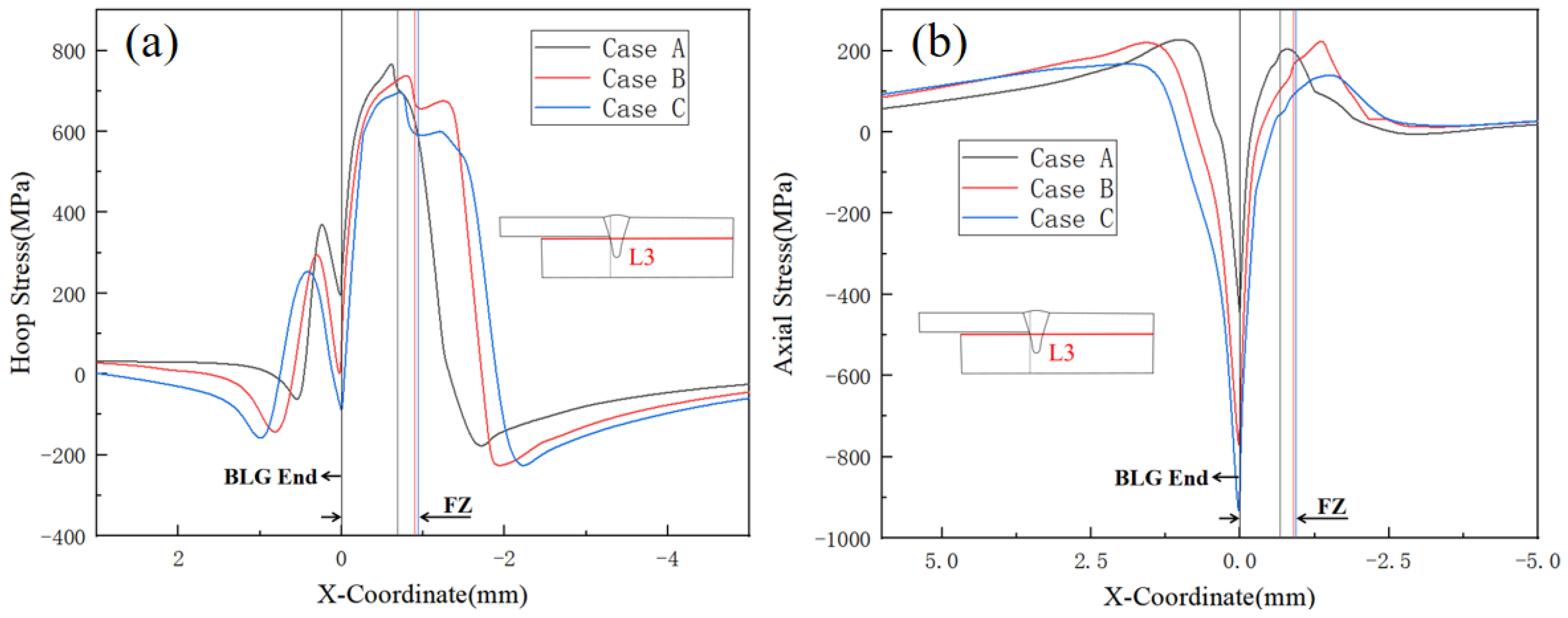
Figure 14a presents the hoop stress distribution characteristics along Path L3 under three laser welding conditions. The stress distribution of all three cases exhibits a high degree of asymmetry, with the peak hoop tensile stress on the left side of the FZ being nearly 400 MPa lower than that on the right side. This is significantly different from the hoop stress distribution along Path L2. Due to the special temperature field and constraint conditions of the bottom-locking structure, two regions that are so close to each other exhibit completely distinct stress distribution states. By comparing the tensile stress data, it can be clearly verified that all three cases follow the evolution law that “the peak stress decreases with the increase in heat input, and the distribution range of the high-stress zone expands synchronously”: the peak stress of Case A is 764 MPa, Case B decreases to 738 MPa, and Case C further reduces to 693 MPa; the distribution range of the high-stress zone for Cases B and C is 40% wider than that of Case A. Figure 14b illustrates the axial stress distribution law along Path L3 under three laser welding conditions. As shown in the figure, a compressive stress state is observed near the BLG End for all three cases. With the increase in distance from the BLG End, the stress rises rapidly and transitions to tensile stress, and the tensile stress level of all cases is relatively low. Within the region of the FZ and its left side (1 > X > 0), the peak stress of all three cases shows a decreasing trend with the increase in heat input.
Figure 14.
Residual stress distributions along Path L3: (a) Hoop residual stress; (b) Axial residual stress.
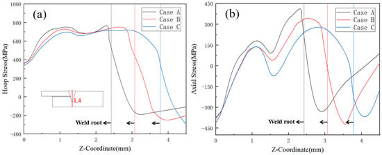
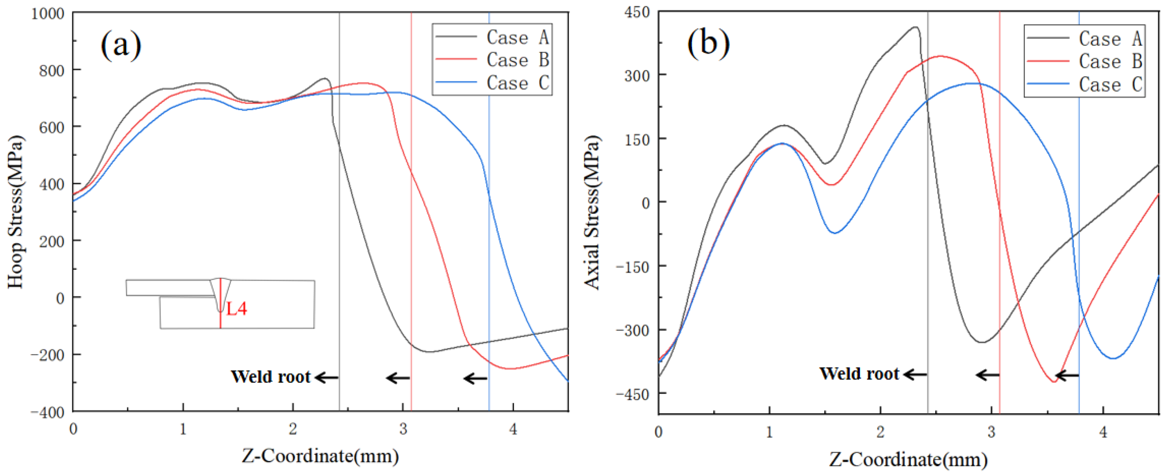
Figure 15a illustrates the hoop residual stress distribution characteristics along Path L4 under three laser welding conditions. As can be seen from the figure, all three cases exhibit relatively high tensile stress in the FZ zone, with the peak stress showing a decreasing trend as the heat input increases. Meanwhile, the extension range of high tensile stress along the thickness direction gradually expands with the increase in heat input. The peak hoop stress of each case is concentrated in a specific interval above the weld root (3 > Z > 2). Figure 15b presents the axial residual stress distribution law along Path L4 under three laser welding conditions. The curve data indicates that the peak axial stress of the three cases also shows a decreasing trend with the increase in heat input.
Figure 15.
Residual stress distributions along Path L4: (a) Hoop residual stress; (b) Axial residual stress.
The BLG End, as a critical stress concentration zone in bottom-locking joints, is subjected to the coupled effects of structural constraint and material mismatch, making it a potential site for fatigue-crack initiation under service conditions in aircraft structures. As shown in earlier quantitative analyses of residual stress, heat input plays a key role in governing axial stress distribution: as heat input rises, the peak axial tensile stress on the TA18 side tends to increase, whereas the peak axial tensile stress at the weld root gradually decreases. In the present study, all three power conditions produced welds with good penetration [18], thereby shifting the high tensile-stress zone at the weld root away from the BLG End region. Notably, Case A (low heat input) yielded the most favorable stress distribution: the tensile stress level on the TA18 side was the lowest, and the high-stress risk zone did not overlap with the BLG End.
It is particularly important to note that if the weld penetration is reduced to the depth of the BLG, a significant axial high-tensile-stress concentration will inevitably develop in the BLG region, severely degrading the mechanical performance of the joint. Based on the findings of this study, the key principle for optimizing the welding process of dissimilar bottom-locking joints can be summarized as follows: while ensuring that the weld penetration exceeds the fitting gap between the two tubes by a sufficient depth, the heat input should be minimized as much as possible. This approach allows the joint to achieve a more favorable residual stress distribution, effectively preventing stress concentration in the BLG region, and thereby ensuring the joint’s service reliability and structural integrity.
5. Conclusions and Prospects
This study conducts comprehensive numerical simulation and experimental research on the laser welding process of TC4/TA18 dissimilar titanium alloy bottom-locking tubes. The core findings are summarized as follows:
- (1)
- The temperature field of the dissimilar titanium alloy bottom-locking structure exhibits significant asymmetry, specifically manifested in the heat-affected zone (HAZ) width of the TA18 thin-walled tube being approximately twice that of the TC4 thick-walled tube. Furthermore, as the laser power increases, the weld penetration depth of the dissimilar alloy joint increases significantly, while the weld width shows only a minor increase.
- (2)
- High hoop tensile stresses in the dissimilar titanium alloy bottom-locking joint are concentrated in the FZ and adjacent areas, with the TA18 thin-walled tube exhibiting higher peak stress than the TC4 thick-walled tube. Notably, as the laser power increases, the distribution range of this high-stress zone expands, while the peak stress value correspondingly decreases.
- (3)
- The axial stress distribution in the dissimilar titanium alloy bottom-locking joint exhibits significant asymmetric characteristics, with the high-stress zone distribution and evolution patterns as follows: on the TA18 titanium alloy side, high tensile stresses are concentrated on the lower surface of the weld, and as the laser power increases, this zone expands with the peak value rising from 217 MPa to 486 MPa; on the TC4 titanium alloy side, high tensile stresses are distributed in the lower part and upper surface of the weld, and with increasing laser power, the high-stress zone in the lower part of the weld shifts downward while the peak value decreases from 442 MPa to 289 MPa.
- (4)
- Stress analysis of the end of the gap in the bottom-locking joint indicates that 600 W is the optimal laser power among the three levels investigated in this study, as it results in the lowest tensile residual stress in the bottom-locking joint gap-end zone.
- (5)
- Future work will focus on two main aspects: first, systematically comparing laser welding with other welding methods, with emphasis on analyzing weld formation, temperature fields, and residual stress distribution to clarify the advantages of laser welding; second, conducting an in-depth investigation into the influence of laser process parameters on residual stress, aiming to identify the optimal parameter set for reducing stress peaks and improving stress distribution.
Author Contributions
M.C.: Writing original draft, Conceptualization, Validation, Writing Review and Editing, Project administration, Funding acquisition, Supervision. D.L.: Writing original draft, Data curation, Visualization. X.Z.: Writing original draft, Conceptualization, Validation. W.W.: Writing original draft, Resources, Validation. Y.W.: Writing original draft, Data Curation, Validation. C.Z.: Writing original draft, Conceptualization, Resources, Validation, Supervision. X.X.: Formal analysis, Conceptualization, Data Curation, Validation. All authors have read and agreed to the published version of the manuscript.
Funding
This work was supported by the Natural Science Foundation of Jiangxi (20242BAB20020).
Data Availability Statement
The original contributions presented in this study are included in the article. Further inquiries can be directed to the corresponding authors.
Acknowledgments
During the preparation of this manuscript/study, the author(s) used DeepSeek-V3.2 to improve the readability and language fluency of the manuscript. The authors have reviewed and edited the output and take full responsibility for the content of this publication.
Conflicts of Interest
The authors declare that they have no known competing financial interests or personal relationships that could have appeared to influence the work reported in this paper.
References
- Jiao, J.; Zou, Q.; Ye, Y.; Xu, Z.; Sheng, L. Carbon fiber reinforced thermoplastic composites and TC4 alloy laser assisted joining with the metal surface laser plastic-covered method. Compos. Part B Eng. 2021, 213, 108738. [Google Scholar] [CrossRef] [Scilit]
- Boyer, R.R. An overview on the use of titanium in the aerospace industry. Mater. Sci. Eng. A 1996, 213, 103–114. [Google Scholar] [CrossRef] [Scilit]
- Gao, X.L.; Zhang, L.J.; Liu, J.; Zhang, J.-X. Effects of weld cross-section profiles and microstructure on properties of pulsed Nd: YAG laser welding of Ti6Al4V sheet. Int. J. Adv. Manuf. Technol. 2014, 72, 895–903. [Google Scholar] [CrossRef] [Scilit]
- Lin, J.; Ma, N.; Liu, X.; Lei, Y. Modification of residual stress distribution in welded joint of titanium alloy with multi electron beam heating. J. Mater. Process. Technol. 2020, 278, 116504. [Google Scholar] [CrossRef] [Scilit]
- Rominiyi, A.L.; Mashinini, P.M. A critical review of microstructure and mechanical properties of laser welded similar and dissimilar titanium alloy joints. J. Adv. Join. Process. 2024, 9, 100191. [Google Scholar] [CrossRef] [Scilit]
- Wang, J.; Wang, J.; Zhao, Y.; Li, Y.; Zhan, X. Microstructure, thermal behavior and tensile properties of laser welded bottom-locking joint for TA15 titanium alloy. Met. Mater. Int. 2023, 29, 1441–1453. [Google Scholar] [CrossRef] [Scilit]
- Kang, X.; Yan, T.; Wang, L.; Gao, Q.; Zhan, X. Study on the distribution, element characteristics, and formation mechanism of porosity during laser welding for Ti-6Al-4V bottom-locking joint. Int. J. Adv. Manuf. Technol. 2022, 123, 2691–2701. [Google Scholar] [CrossRef] [Scilit]
- Zhan, Y.; Zhang, E.; Ge, Y.; Liu, C. Residual stress in laser welding of TC4 titanium alloy based on ultrasonic laser technology. Appl. Sci. 2018, 8, 1997. [Google Scholar] [CrossRef] [Scilit]
- Rauschenberger, J.; Cenigaonaindia, A.; Keseberg, J.; Vogler, D.; Gubler, U.; Liébana, F. Laser hybrid joining of plastic and metal components for lightweight components. In Proceedings of the High-Power Laser Materials Processing: Lasers, Beam Delivery, Diagnostics, and Applications IV, San Francisco, CA, USA, 7–12 February 2015; Volume 9356, pp. 58–65. [Google Scholar]
- Ortiz, M.; Liébana, F.; Etayo, J.M.; Zubia, A.; Papaioannou, C.; Bikas, H.; Stavropoulos, P.; Ares, F.; Modi, V. A simulation-based thermal process control method for multi-material laser-joining operations. Int. J. Comput. Integr. Manuf. 2025, 1–15. [Google Scholar] [CrossRef] [Scilit]
- Gangwar, K.; Ramulu, M. Residual stress measurement using X-ray diffraction in friction stir-welded dissimilar titanium alloys. Materials 2024, 17, 1482. [Google Scholar] [CrossRef] [Scilit]
- Zhang, J.X.; Xue, Y.; Gong, S.L. Residual welding stresses in laser beam and tungsten inert gas weldments of titanium alloy. Sci. Technol. Weld. Join. 2005, 10, 643–646. [Google Scholar] [CrossRef] [Scilit]
- Junaid, M.; Rahman, K.; Khan, F.N.; Bakhsh, N.; Baig, M.N. Comparison of microstructure, mechanical properties, and residual stresses in tungsten inert gas, laser, and electron beam welding of Ti–5Al–2.5 Sn titanium alloy. Proc. Inst. Mech. Eng. Part L J. Mater. Des. Appl. 2019, 233, 1336–1351. [Google Scholar] [CrossRef] [Scilit]
- Xie, P.; Zhao, H.Y.; Wu, B.; Gong, S.-L. Using finite element and contour method to evaluate residual stress in thick Ti-6Al-4V alloy welded by electron beam welding. Acta Metall. Sin. (Engl. Lett.) 2015, 28, 922–930. [Google Scholar] [CrossRef] [Scilit]
- Frankel, P.; Preuss, M.; Steuwer, A.; Withers, P.J.; Bray, S. Comparison of residual stresses in Ti–6Al–4V and Ti–6Al–2Sn–4Zr–2Mo linear friction welds. Mater. Sci. Technol. 2009, 25, 640–650. [Google Scholar] [CrossRef] [Scilit]
- Xie, P.; Zhao, H.; Liu, Y. Measuring residual stresses in linear friction welded joints composed by dissimilar titanium. Sci. Technol. Weld. Join. 2016, 21, 351–357. [Google Scholar] [CrossRef] [Scilit]
- Gao, X.; Si, H.; Yue, X.; Jing, Y.; Li, Z. Brazing process of TC4/TA18 titanium alloy honeycomb sandwich construction. Aeronaut. Manuf. Technol. 2015, 11, 109–112. [Google Scholar]
- Yang, B.; Tan, C.; Chen, G.; Sun, H.; Liu, F.; Wu, L.; Chen, B.; Song, X. Online monitoring system for welding states of bottom-locking joints in high-speed trains via multi-information fusion and 3DCNN. J. Manuf. Process. 2024, 113, 105–116. [Google Scholar] [CrossRef] [Scilit]
- Guo, J.; Fu, H.; Pan, B.; Kang, R. Recent progress of residual stress measurement methods: A review. Chin. J. Aeronaut. 2021, 34, 54–78. [Google Scholar] [CrossRef] [Scilit]
- ASTM E837; Standard Test Method for Determining Residual Stresses by the Hole-Drilling Strain-Gage Method. ASTM International: West Conshohocken, PA, USA, 2020.
- Li, Y.; Li, Y.; Zhang, C.; Lei, M.; Luo, J.; Gou, X.; Deng, D. Effect of structural restraint caused by the stiffener on welding residual stress and deformation in thick-plate T-joints. J. Mater. Res. Technol. 2022, 21, 3397–3411. [Google Scholar] [CrossRef] [Scilit]
- Zhao, H.; Yu, C.; Liu, Z.; Liu, C.; Zhan, Y. A novel finite element method for simulating residual stress of TC4 alloy produced by laser additive manufacturing. Opt. Laser Technol. 2023, 157, 108765. [Google Scholar] [CrossRef] [Scilit]
- Cheng, Z.; Abd El-Aty, A.; Zhang, R.; Cheng, C.; Guo, X.; Tao, J. Finite element modeling and experimental investigation on manufacturing TA18 alloy pipes via hot free bending forming technology: Forming characteristics and process optimization. J. Mater. Res. Technol. 2024, 29, 5225–5240. [Google Scholar] [CrossRef] [Scilit]
- Deng, D. Influence of deposition sequence on welding residual stress and deformation in an austenitic stainless steel J-groove welded joint. Mater. Des. 2013, 49, 1022–1033. [Google Scholar] [CrossRef] [Scilit]
- Sun, J.; Nitschke-Pagel, T.; Dilger, K. Generation and distribution mechanism of welding-induced residual stresses. J. Mater. Res. Technol. 2023, 27, 3936–3954. [Google Scholar] [CrossRef] [Scilit]
- Deng, D.; Murakawa, H.; Liang, W. Numerical and experimental investigations on welding residual stress in multi-pass butt-welded austenitic stainless steel pipe. Comput. Mater. Sci. 2008, 42, 234–244. [Google Scholar] [CrossRef] [Scilit]
- Deng, D.; Murakawa, H. Prediction of welding residual stress in multi-pass butt-welded modified 9Cr–1Mo steel pipe considering phase transformation effects. Comput. Mater. Sci. 2006, 37, 209–219. [Google Scholar] [CrossRef] [Scilit]
- Perić, M.; Garašić, I.; Gubeljak, N.; Tonković, Z.; Nižetić, S.; Osman, K. Numerical simulation and experimental measurement of residual stresses in a thick-walled buried-arc welded pipe structure. Metals 2022, 12, 1102. [Google Scholar] [CrossRef] [Scilit]
- Zhao, L.; Liang, J.; Zhong, Q.; Yang, C.; Sun, B.; Du, J. Numerical simulation on the effect of welding parameters on welding residual stresses in T92/S30432 dissimilar welded pipe. Adv. Eng. Softw. 2014, 68, 70–79. [Google Scholar] [CrossRef] [Scilit]
- Deng, D.; Murakawa, H. Numerical simulation of temperature field and residual stress in multi-pass welds in stainless steel pipe and comparison with experimental measurements. Comput. Mater. Sci. 2006, 37, 269–277. [Google Scholar] [CrossRef] [Scilit]
- Obeid, O.; Alfano, G.; Bahai, H.; Jouhara, H. Numerical simulation of thermal and residual stress fields induced by lined pipe welding. Therm. Sci. Eng. Prog. 2018, 5, 1–14. [Google Scholar] [CrossRef] [Scilit]

Disclaimer/Publisher’s Note: The statements, opinions and data contained in all publications are solely those of the individual author(s) and contributor(s) and not of MDPI and/or the editor(s). MDPI and/or the editor(s) disclaim responsibility for any injury to people or property resulting from any ideas, methods, instructions or products referred to in the content. |
© 2025 by the authors. Licensee MDPI, Basel, Switzerland. This article is an open access article distributed under the terms and conditions of the Creative Commons Attribution (CC BY) license.