Abstract
For the construction of long and continuous railway lines as well as the replacement of defected rails, rails are joined using flash-butt welding. Under various localized temperatures and thermo-mechanical stresses, a residual stress can develop in the flash-butt welded joint. The residual stress can affect the performance and reliability of the welded rail, particularly in terms of progressive structural damage caused by repeated wheel load. In the present work, the mechanisms of residual stress formation in a flash-butt welded rail and the influence of upsetting force (including its temperature range and magnitude) were investigated using the thermal elastic–plastic finite element analysis. The formation mechanisms of residual stress involved the changes in thermal expansion coefficient, strain, and elastic modulus of the welded joint with respect to temperature. The calculated cooling temperatures and residual stresses in the flash-butt welded joint were in good agreement with the measured results. Compressive residual stresses were observed around the rail head and the rail foot (i.e., approximately −648 MPa at the rail head and −495 MPa at the rail foot), while tensile residual stresses were observed at the rail web (i.e., approximately 165 MPa). It was observed that the investigated compressive upsetting force predominantly induced plastic deformation within the welded joint, resulting in minimal alteration of stress. Consequently, the investigated ranges of upsetting temperature and upsetting forces had an insignificant impact on the formation of residual stress.
1. Introduction
For the construction of long and continuous railway lines as well as the replacement of defected rails, rails are joined using various welding methods. The two most common welding techniques for joining rails are aluminothermic welding and flash-butt welding [1]. Aluminothermic welding is a casting process, i.e., the melted alloy is filled into the gap between rails, left to solidify, thus forming a welded joint. On the other hand, the flash-butt welding is a form of electric-resistance welding. Flash-butt rail welding is usually preferable due to fewer defects in a welded joint as well as the low failure rate under repeated wheel load. Moreover, flash-butt welding is a convenient and fast welding technique, which can be performed either in the field using a mobile welding machine or in a fixed plant [2].
During flash-butt welding [1,3], two rails are held between the electrode clamps. Initially, two rail ends are slightly separated, and arcing is created between them to generate a stable temperature distribution (i.e., preheating). After preheating, a flash arcing is created to generate the semi-liquid stage of rail ends (i.e., flashing). Subsequently, both rail ends are pressed together (i.e., upsetting), and the flash-butt welded rail is left to cool in an ambient environment (i.e., cooling). The flash-butt welded joint is completely formed after cooling. The deformed metals at rail head and rail foot are removed from the welded joint using a grinding machine (i.e., trimming).
Under various localized temperatures and thermo-mechanical stresses, residual stress can develop in the flash-butt welded joint. The residual stress can affect the performance and reliability of the welded rail, particularly in terms of progressive structural damage caused by repeated loading (i.e., engineering fatigue). Below the neutral surface of the rail (i.e., toward the rail foot), the cyclic tensile stress from the repeated wheel load can combine with the residual stress in the welded joint. The combined cyclic stress tends to decrease the fatigue resistance of the welded joint, especially at the flaw of the welded joint [4]. On the other hand, above the neutral surface of the rail (i.e., around the rail head), the interaction between the cyclic contact stress from the repeated wheel load and the residual stress can influence the rolling contact fatigue behavior of the rail. Lee et al. [5] experimentally and numerically investigated the interaction between the cyclic contact stress from repeated wheel load and the residual stress of repair welded rail. They found that the residual stress influenced the rolling contact fatigue behavior of the rail head, i.e., cracks were found shortly beneath the welded layer.
In previous works, several techniques of residual stress measurement were applied to measure the residual stresses on the outer surfaces of welded joints. Ma et al. [6] experimentally investigated the residual stresses in a flash-butt welded joint using the hole-drilling strain-gage method. Longitudinal compressive stress was observed on the surface of the rail head, while longitudinal tensile stress was observed on the surface of the rail web. Yan et al. [7] measured the residual stresses in a flash-butt weld of the U71Mn railway rail using the X-ray diffraction method. They found longitudinal compressive stress in the foot and head regions, and longitudinal tensile stress in the web region. Ma et al. [8] measured the residual stresses in a heat-affected zone of the welded joint using the Debye-ring X-ray stress measurement. The measured residual stresses of the welded joint met the Chinese standard, and the induction normalizing treatment provided the best service performance due to an improvement in grain size uniformity. Unfortunately, there are some limitations of the direct residual stress measurement. For example, the measurement of residual stress depends on the locations of the applied sensors and/or probes of the measurement equipment. Consequently, the overall distribution of residual stress in the welded joint may not be effectively measured. Moreover, the accuracy of residual stress measurement, especially the measurement derived from the residual strain via Hooke’s law, could be compromised in regions with complex and relatively high magnitudes of residual stress [9].
As an alternative method for evaluating the residual stresses in a flash-butt welded rail, the distribution of residual stresses in the welded joint has been numerically evaluated via finite element analysis (FEA). Skyttebol et al. [10] numerically evaluated the influence of residual stress on the fatigue crack growth at the rail head region of a flash-butt welded joint. The calculated residual stresses corresponded to the measured results in a welded rail. They proposed typical crack sizes in a welded joint that may grow and fail in a very short time if the residual stress field interacts with the axle load. Ma et al. [6] experimentally investigated the residual stresses in a flash-butt welded joint, and compared them with those from the FEA. Both experimental and numerical results suggested that the solid-state phase transformation plays a very important role in the formation of residual stress. Ghazanfari and Tehrani [11,12] proposed that four key parameters (i.e., the maximum temperature during the welding process, the total welding time, the upsetting time, and the upsetting force) influence the size, microstructure, and hardness profile of the heat-affected zone in a flash-butt welded joint. To reduce the possibility of failure in the welded rail, the parameters of flash-butt welding were optimized to decrease the critical tensile residual stresses during welding. They also numerically investigated the residual stresses in a welded rail, and compared them with the measured residual stresses [13]. FEA results were in good agreement with the measurements of residual stress.
The influence of post-weld heat treatment (PWHT) on the residual stress in flash-butt welded joints was investigated by Tawfik et al. [14,15]. Tawfik et al. [14] applied the neutron diffraction technique to analyze the residual stresses in an AS60 flash-butt welded rail cooled under normal operating conditions. The measured results were used for the validation of FEA. Subsequently, the FEA was used for the calculation of stress-time histories for the welding under normal cooling in air, rapid PWHT, and accelerated cooling using water spray [15]. They found that the rapid quenching before the complete austenite–pearlite transformation can increase the tensile residual stress. Pereira et al. [16] performed a metallographic examination of a flash-butt weld joint. They found that there was no formation of acicular microstructures (i.e., martensite/bainite) in the web region and the rail foot, which were the regions with a higher cooling rate. Therefore, the expansion of martensite during the phase transformation was not considered in their numerical simulation of residual stresses. A concentration of vertical residual stresses was observed in the web region, while the presence of horizontal compression residual stresses was mostly superficial at the rail head region.
Although there are various works [6,10,11,12,13,14,15,16] devoted to the numerical investigation of residual stress in flash-butt welded rails, the mechanism of residual stress formation in flash-butt welded rails at various stages of heating and cooling has not been clearly discussed, and the process of residual stress formation in a welded joint is far from completely understood. It is therefore the objective of the present work to investigate the mechanisms of residual stress formation in a flash-butt welded rail. The numerical residual stresses in the flash-butt welded joint were validated with the measured residual stresses. Subsequently, the validated FEA model was applied to investigate the mechanisms of residual stress formation in the flash-butt welded rail, and the influence of the upsetting force, including its temperature range and magnitude. The findings could be used as guidelines for determining residual stresses in the flash-butt welded rail and improving its reliability.
2. Material and Methods
2.1. Flash-Butt Welded Rail
The 60E1 rail (i.e., BS EN 13674-1 [17]) was selected for the present work. The geometry of the rail is shown in Figure 1. The mechanical properties of the rail steel at an ambient temperature (i.e., 25 °C), and at high temperatures [10] are listed in Table 1.
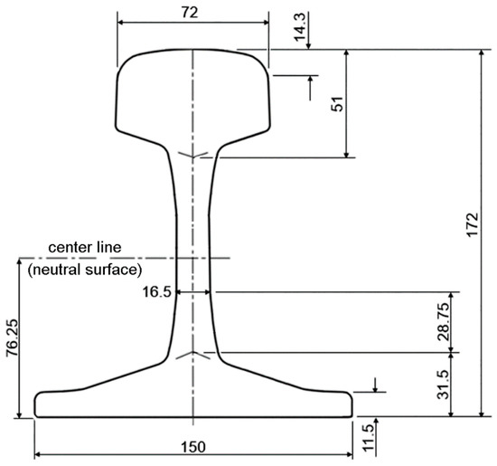
Figure 1.
Geometry of 60E1 rail (dimension in mm).

Table 1.
Mechanical properties and thermal expansion coefficients of rail steel [10].
The parameters of the flash-butt welding process of rail (Figure 2) selected for this study was the same as those used by Ma et al. [6]. Two 1000 mm rails were used for the flash-butt welding. Starting from an initial temperature of 25 °C, the temperature on the cross section of each rail end was increased to the peak temperature of 1470 °C within a period of 80 s. At 25 s, after the peak temperature (i.e., the cooling temperature of 880 to 780 °C), both rail ends are pressed together. An upsetting force of 450 kN was applied in the longitudinal axis of the rail for 10 s. The welded rail was cooled in an ambient environment until it reached the ambient temperature of 25 °C. Afterward, the deformed metals at the rail head and the rail foot were removed from the flash-butt welded joint. It is noted that actual flash-butt welding involves the applications of electric current to generate the temperature. These processes are more complex than the selected flash-butt welding process in the present numerical study, which was simplified to gain fundamental knowledge of the mechanisms of residual stress formation in the flash-butt welded joint of a rail.
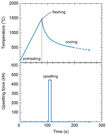
Figure 2.
Parameters of the flash-butt welding of rail [6].
2.2. Governing Equations for Flash-Butt Welding
According to the AREMA recommendation [18], flash-butt welding is controlled to minimize the amount of martensite in any rail region. Also, the findings of both Skyttebol et al. [10] and Pereira et al. [16] reveal no major change in the hardness and microstructure of the heat-affected zone (HAZ). Thus, phase transformation is not considered in the present numerical investigation.
From the ambient temperature of 25 °C to the peak temperature of 1470 °C (i.e., heating), the heat flux vector was applied to the weld zone of 4 mm width to represent the heat generated during flash-butt welding (Figure 3). Subsequently, cooling, upsetting, and trimming were numerically simulated. The formation of residual stress was evaluated at various stages of heating and cooling. To simplify the numerical simulation, it was assumed that the thermal radiation is negligible, and not considered in the present investigation. Therefore, the change in temperature with time was calculated based on the specific heat capacity, thermal conductivity, and thermal convection. The governing equations for the heat transfer analysis, non-linear isotropic Fourier heat flux, and thermal convection are given as follows:
where ρ is the density of material (i.e., 7.85 × 10⁻⁶ kg/mm3 for rail steel [19]), c is the specific heat capacity, hc is the convection coefficient, k is the thermal conductivity, T is the temperature, q is the heat flux vector, Q is the internal heat generation rate, Ts is the peak temperature at the weld surface, To is the ambient temperature, and t is the time. These temperature-dependent thermal properties [11,19] are shown in Figure 4.
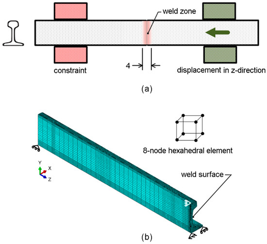
Figure 3.
Flash-butt welded rail: (a) schematic illustration, and (b) FEA model (dimension in mm).
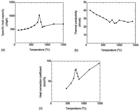
Figure 4.
Temperature-dependent thermal properties of rail steel: (a) specific heat capacity [19], (b) thermal conductivity [19], and (c) heat convection coefficient in air [11].
Because of the temperature gradient, a thermally induced strain (i.e., thermal strain) occurs during the flash-butt welding. The thermal strain can be calculated as follows:
where εT is the thermal strain, and α is the thermal expansion coefficient. The thermal expansion coefficients of the rail steel at ambient temperature (i.e., 25 °C) and at high temperatures [10] are listed in Table 1.
To simulate upsetting, one rail was constrained, while the other rail was moved to compress. A displacement was applied to the rail end until an upsetting force of 450 kN was achieved. According to the preliminary FEA, it is observed that the deformation of the flash-butt welded joint was elastic–plastic deformation. Thus, the linear elastic and plastic deformation with linear hardening was assumed during flash-butt welding as follows [20]:
where σ is the normal stress, ε is the normal strain, σY is the yield stress, εY is the yield strain, E is the elastic modulus, and EH is the hardening modulus. The interaction between the thermal strain and the mechanical strain from the upsetting force is converted to stress. Linear interpolation was applied for the determination of the mechanical properties and thermal expansion coefficients at various temperatures from the reference data (Table 1).
Above the annealing of steel (i.e., approximately 800 °C), the deformation has a marginal effect on the formation of residual stress [21]. Thus, it is assumed that the residual stress of flash-butt welded rail cannot be formed above the annealing temperature of 800 °C. At the end of cooling, trimming was performed by removal of the excess steel around the rail head and the rail foot of the weld surface, and the redistribution of residual stress was numerically calculated.
2.3. Finite Element Analysis
The 3D thermal elastic–plastic FEA was applied to numerically simulate the residual stress in the flash-butt welded joint using a commercial FEA software (i.e., ABAQUS [22]). FEA model of the flash-butt welded rail is shown in Figure 3. Because the flash-butt welded rail is symmetrical on the weld surface and the y-z plane, the FEA model used only a quarter of the flash-butt welded rail to reduce the calculation time. The 8-node hexahedral elements with trilinear displacement and temperature features (i.e., C3D8RT) were selected for the FEA model. The fine elements were applied around the weld surface to obtain the accurate residual stress. As the minimal temperature above which the material loses its hardening memory, an annealing temperature (Tα) of 800 °C was set during the FEA. To simulate trimming at the end of cooling, the elements that deform beyond the profile of the rail head and the rail foot were deactivated, and the redistribution of residual stress was calculated among the remaining elements.
During heating, the temperature of the weld zone was varied with intervals of 50 steps from zero to the peak temperature of 1470 °C. As the boundary conditions, the displacements in z-direction of the weld surface, x-direction of the symmetrical y-z plane, and y-direction of the bottom surface of flash-butt welded rail were constrained. The cooling temperature and residual stress were numerically calculated until the temperature of the flash-butt welded joint reached the ambient temperature of 25 °C. To minimize the influence of element size, the element size was adjusted until further changes in the element size did not affect the calculated results. The smallest element size around the weld surface is 0.25 mm. The FEA model consists of 36,839 nodes and 31,356 elements.
3. Results and Discussion
3.1. Cooling Temperature
The temperatures at various stages of cooling were numerically calculated and compared with the measured results. At the rail web of the welded joint, the calculated cooling temperature was compared with those measured by Ghazanfari and Tehrani [11], and numerically calculated by Ma et al. [6], as shown in Figure 5. Initially, the cooling temperature rapidly decreases, i.e., from 1470 to 450 °C, within approximately 150 s. The present calculated cooling temperature is in good agreement with the measurement [11]. Below 450 °C, where the measured cooling temperature was discontinued, the decrease in cooling temperature becomes slower. The present calculated result is in good agreement with that of Ma et al. [6] until the temperature of 150 °C, where their calculation of cooling temperature was terminated. To provide the complete cooling process of flash-butt welding, the present FEA was continued until the temperature reached the ambient temperature of 25 °C. It was found that the total cooling period is approximately 3 h.
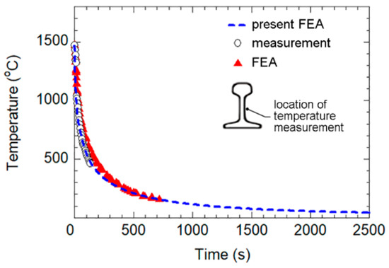
Figure 5.
Cooling temperature at the rail web of welded joint predicted through FEA [6] and measured [11] using the thermography camera.
3.2. Residual Stress
Based on the hole-drilling strain-gage method (i.e., ASTM E837 [9]), Skyttebol et al. [10] measured the residual stress on a flash-butt welded joint of an UIC grade 900A rail. The residual strains in the longitudinal direction of rail were measured on the surface (i.e., the holes with 0.25 mm depth and 1.27 mm radius). Subsequently, the measured residual strain was converted to the residual stress. Ma et al. [6] also measured the residual stresses of a flash-butt welded joint using the same method. The calculated residual stresses at the end of cooling were compared with the measured residual stresses [6,10], as shown in Figure 6. The behaviors of residual stress obtained from the present FEA and the measurements are similar. The compressive residual stresses are observed around the rail head and the rail foot, while the tensile residual stresses are observed at the rail web. However, at the rail head and the rail foot, the calculated residual stresses are higher than the measured results [6,10], while at the rail web, the calculated residual stresses are in good agreement with the measured results [6].
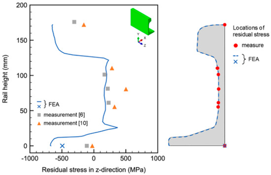
Figure 6.
Residual stresses on the outer surface of a flash-butt welded joint predicted through FEA and measured using the hole-drilling strain-gage method [6,10].
As mentioned in ASTM E837 [9], the hole-drilling strain-gage method is applicable for the accurate measurement of residual stress when the residual stresses do not: (i) vary significantly with depth, and (ii) exceed half of the yield strength. At the rail web, it was observed from the FEA that the calculated residual stress in z-direction varies slightly with depth (i.e., the range of 164 to 165 MPa with 0.25 mm depth). Moreover, the magnitudes of calculated residual stress at the rail web are lower than half of the yield stress of rail steel (i.e., 420 MPa). Thus, the hole-drilling strain-gage method is applicable for the accurate measurement of residual stress at the rail web, i.e., the calculated residual stresses correspond well with the measured results [6]. On the other hand, at the rail head and the rail foot, the variations of calculated residual stress with depth are higher than that at the rail web (i.e., the range of −649 to −647 MPa with 0.25 mm depth of the rail head, and the range of −497 to −492 MPa with 0.25 mm depth of the rail foot). Moreover, at the rail head and the rail foot, the calculated residual stresses in z-direction are significantly higher than half of the yield stress of rail steel. Thus, the hole-drilling strain-gage method may not provide accurate residual stress measurement at the rail head and the rail foot.
At various distances in the longitudinal direction from the weld surface, the measured residual stresses [6] and the present calculated residual stresses in the longitudinal direction (i.e., z-direction) at the rail head and the rail web, and in the lateral direction (i.e., x-direction) at the rail foot were compared, as shown in Figure 7. At the rail head and approximately 20 mm from the weld surface, the magnitudes as well as the variation of residual stresses in the longitudinal direction with the hole depths are marginal. Therefore, the hole-drilling strain-gage method can measure accurate residual stresses, i.e., the measured and the present calculated compressive residual stresses in the longitudinal direction are nearly similar (Figure 7a). Regarding the residual stresses in the longitudinal direction at the rail web (Figure 7b) and in the lateral direction at the rail foot (Figure 7c), it is observed from the present FEA that the magnitudes as well as the variation of residual stresses with the depth of the hole-drilling strain-gage method are also marginal. Thus, the hole-drilling strain-gage method can measure accurate residual stresses, i.e., the calculated and measured residual stresses are in good agreements.
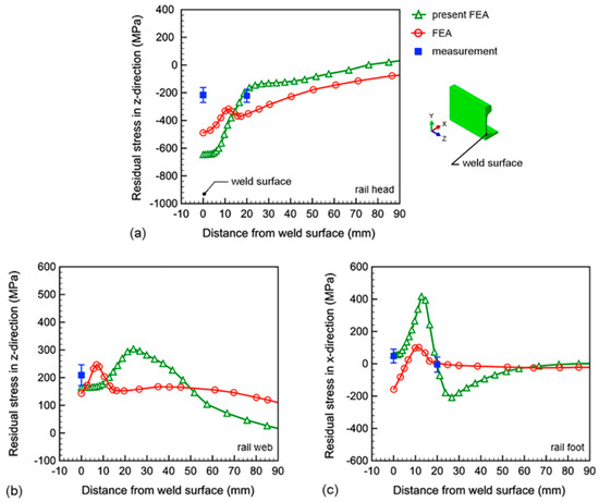
Figure 7.
Residual stresses on the outer surface of flash-butt welded rail predicted through FEA and measured using the hole-drilling strain-gage method: (a) the longitudinal direction at the rail head [6], (b) the longitudinal direction at the rail web, and (c) the lateral direction at the rail foot.
Using an in-house FEA program, Ma et al. [6] numerically predicted the residual stresses of a flash-butt welded joint. The influence of solid-state phase transformation was considered in their numerical calculation. Their FEA results [6] were compared with the present FEA results, as shown in Figure 7. The residual stresses obtained from the present FEA (i.e., without the consideration of solid-state phase transformation) are in better agreement with the measured residual stresses. Currently, comprehensive knowledge regarding the effects of phase transformation on the formation of residual stress in welded joints is far from complete. Thus, further investigation is required for future works.
3.3. Residual Stress Formation Mechanisms
The distributions of residual stresses, i.e., von Mises stress (σv), normal stress in the longitudinal direction (σz), normal stress in the lateral direction (σx), and normal stress in the vertical direction (σy) after flash-butt welding (i.e., the situation when the cooling temperature of each node of the FEA model becomes 25 °C) are shown in Figure 8a–d, respectively. It is observed that the σv is significantly high around the outer surfaces of the rail head and the rail foot. Moreover, the compressive σz is the main contribution of σv because σz is high around the outer surfaces of the rail head and the rail foot, and its magnitude is significantly greater than those of σx and σy.
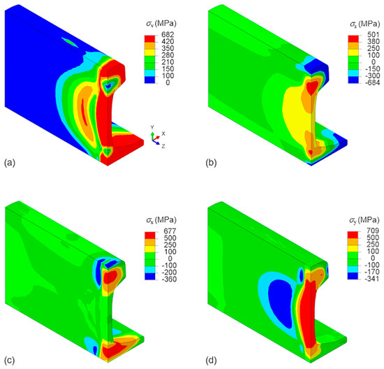
Figure 8.
Distributions of residual stresses after flash-butt welding: (a) von Mises stress, (b) normal stress in the longitudinal direction, (c) normal stress in the lateral direction, and (d) normal stress in the vertical direction.
It is important to note that fatigue cracks typically propagate in the direction perpendicular to the cyclic stress, i.e., the stress in the longitudinal direction of the rail due to the repeated wheel load [4]. Accordingly, the residual stress in the longitudinal direction (σz) of the flash-butt welded joint can interact with the cyclic contact stress around the rail head and/or the cyclic tensile stress around the rail foot, potentially impacting the fatigue life of the welded rail. Thus, the σz of the flash-butt welded joint was selected for the investigation of residual stress formation mechanisms of the flash-butt welded rail.
The σz at the rail head and the rail foot of the flash-butt welded joint at various temperatures are compared, as shown in Figure 9. The formation pattern of σz around the rail head is not significantly different from that around the rail foot. During the heating process (Figure 9a), the σz increases up to approximately 300 °C, subsequently decreases with temperature, and reaches zero at the peak temperature of 1470 °C. On the other hand, during the cooling process (Figure 9b), the σz increases up to approximately 1300 °C, subsequently decreases with temperature, and becomes compressive σz when the cooling temperature falls below approximately 1100 °C. Since the formation patterns of σz around the rail head and the rail foot of the flash-butt welded joint are similar, the σz around the rail foot of the flash-butt welded joint was selected for investigating the mechanisms of residual stress formation during the heating and cooling processes.
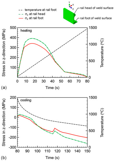
Figure 9.
Residual stresses in the longitudinal direction of flash-butt welded joint: (a) heating process, and (b) cooling process.
3.3.1. Heating Process
At various heating stages, the formation of residual stress in the welded joint is influenced by the properties of the rail steel and the deformation of the welded rail. Thus, the changes in thermal expansion coefficient, strain in the longitudinal direction (εz) at the rail foot and moduli of rail steel (i.e., the elastic moduli and the hardening moduli), and stress in the longitudinal direction (σz) at the rail foot during various heating stages are shown in Figure 10. The formation mechanisms of residual strain (εz) and residual stress (σz) at each heating stage are discussed as follows.
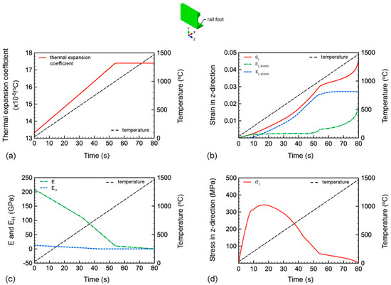
Figure 10.
Properties of rail steel and mechanical responses at the rail foot of the welded joint during various heating stages: (a) thermal expansion coefficient, (b) strain in the longitudinal direction of rail, (c) elastic and hardening moduli, and (d) stress in the longitudinal direction of rail.
Between temperatures of 25 and 1000 °C, the thermal expansion coefficient exhibits a rapid increase with the heating temperature (Figure 10a). The increases in temperature and thermal expansion coefficient result in a mismatch in thermal strains between the welded joint and the rail far from the weld surface, leading to an elevation in εz (Figure 10b). From 1000 to 1470 °C, the thermal expansion coefficient of the welded joint becomes stable, i.e., only the rise in temperature impacts the elevation of εz. By using the elastic moduli and the yield stresses of the rail steel at various temperatures (Table 1), the corresponding yield strains were estimated, and used in calculating the elastic strain in the longitudinal direction of the rail (εz,elastic) and the plastic strain in the longitudinal direction of the rail (εz,plastic). Due to the low yield stress during the heating process, the εz,plastic surpasses εz,elastic (Figure 10b).
Based on the εz,elastic, εz,plastic, elastic moduli (E) and hardening moduli (EH) at various temperatures, the σz was calculated using Equations (5) and (6). The comparison of E and EH at different stages of heating is shown in Figure 10c. Between temperatures of 25 and 1000 °C, the E exhibits a rapid decrease with increasing temperature. However, the rate of decrease significantly reduces when the heating temperature exceeds 1000 °C. Between temperatures of 25 and 1470 °C, the EH is considerably lower than E, and reaches zero at temperatures above 800 °C, indicating steel annealing. Therefore, it is reasonable to assume that the influence of E on the formation of σz is stronger than that of EH.
Between temperatures of 25 and 300 °C, the εz,elastic increases with the heating temperature (Figure 10b), while E decreases (Figure 10c). Based on FEA and Equation (5), it is evident that the influence of εz,elastic is greater than that of E, resulting in an increase in σz from 25 to 300 °C (Figure 10d). Between temperatures of 300 and 1000 °C, the εz,elastic becomes stable with the heating temperature, while E continues to decrease. Consequently, E plays the primary role in the formation of σz, leading to a decrease in σz from 300 to 1000 °C. Beyond 1000 °C, the εz,elastic once again increases with the heating temperature, while E exhibits a slight decrease. At this stage, it is observed that the influence of E exceeds that of εz,elastic, resulting in a slight decrease in σz with the heating temperature. Eventually, at the peak temperature of 1470 °C, the σz becomes zero.
Numerical investigations were conducted to examine the residual stresses in other directions (i.e., σx and σy) throughout the entire welded joint. Similar behavior was observed, i.e., the residual stresses reached zero at the peak temperature of 1470 °C. However, in contrast to the residual stresses, the residual strains remained in the welded joint at the end of the heating process (Figure 10b). These residual strains could have an impact on the formations of residual strain and residual stress during the cooling process, which will be discussed in the following section.
3.3.2. Cooling Process
At various cooling stages, the changes in thermal expansion coefficient, strain in the longitudinal direction (εz) at the rail foot of the welded joint and moduli of rail steel (i.e., the elastic moduli and the hardening moduli), and stress in the longitudinal direction (σz) at the rail foot of the welded joint are shown in Figure 11. The formation mechanisms of residual strain (εz) and residual stress (σz) at each cooling stage are discussed as follows.
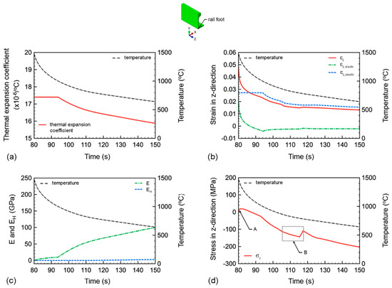
Figure 11.
Properties of rail steel and mechanical responses at the rail foot of the welded joint during various cooling stages: (a) thermal expansion coefficient, (b) strain in the longitudinal direction of rail, (c) elastic and hardening moduli, and (d) stress in the longitudinal direction of rail.
Between temperatures of 1470 and 1000 °C, the thermal expansion coefficient is stable, i.e., it does not change with decreasing temperature (Figure 11a). At this cooling stage, only a decrease in cooling temperature causes the decrease in εz (Figure 11b). However, below 1000 °C, the thermal expansion coefficient exhibits a decrease with decreasing temperature. The decrease in εz is therefore caused by the combination between the decrease in temperature and the decrease in thermal expansion coefficient, as observed in Figure 11b. When compared with the development of εz during the heating process, i.e., when the εz tends to increase with the increase in heating temperature (Figure 10b), the εz tends to decrease with the decrease in cooling temperature. However, similar to the previous investigation of the heating process, it is observed that εz,plastic is greater than εz,elastic. Because the yield strain decreases with decreasing temperature, the εz,elastic decreases, and becomes stable compression at the cooling temperature below 1000 °C (Figure 11b).
The comparison of E and EH at different cooling stages is shown in Figure 11c. Because EH is significantly lower than E, it is reasonable to assume that the influence of E on the formation of σz is stronger than that of EH. Between temperatures of 1470 and 1000 °C, the E exhibits a slight increase with decreasing temperature. The rate of increase becomes notably higher when the cooling temperature falls below 1000 °C. Since the decrease in cooling temperature over time follows a non-linear pattern, the increase in E also exhibits a non-linear behavior, as shown in Figure 11c.
During the beginning of the cooling process (1470 to 1000 °C), εz,elastic decreases with decreasing temperature (Figure 11b), while E increases with decreasing temperature (Figure 11c). Based on FEA and Equation (5), it is evident that the influence of E exceeds that of εz,elastic, resulting in a slight increase in σz from 1470 to 1300 °C (location A in Figure 11d). However, from 1300 to 1000 °C, the influence of εz,elastic becomes greater than that of E, resulting in a decrease in σz with decreasing temperature. Eventually, σz becomes compressive stress at the temperature below 1100 °C. Due to the stable compression of εz,elastic at temperatures below 1000 °C, the compressive σz primarily depends on the increase in E as the temperature decreases. Consequently, the compressive σz increases as the temperature decreases below 1000 °C. During upsetting (i.e., between temperatures of 880 and 780 °C), the drop in compressive σz is observed (region B in Figure 11d).
During the upsetting process, the changes in εz and σz at the rail foot of the welded joint are shown in Figure 12a,b, respectively. The applied compressive upsetting strain and stress at the rail end are also included in the figures for comparison. The applied compressive upsetting strain causes the slight reduction in tensile εz of the welded joint (Figure 12a). In the upsetting temperature range of 880 to 780 °C, the yield stress and hardening modulus of rail steel are extremely low. Consequently, the deformation of the welded joint is dominated by plastic deformation, as observed in Figure 11b. In this scenario, the applied compressive upsetting force does not affect the change in σz of the welded joint (Figure 12b). However, during the unloading phase of the upsetting force, the compressive σz of the welded joint experiences a spring-back effect, resulting in a slight decrease due to the relaxation of elastic deformation.
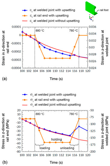
Figure 12.
Mechanical responses at the rail foot of the welded joint during the upsetting process: (a) strains in the longitudinal direction, and (b) stresses in the longitudinal direction.
3.4. Influence of Upsetting on Residual Stress Formation
During the upsetting process, the range of upsetting temperature and the magnitude of upsetting force can potentially affect the development of residual strain and residual stress in flash-butt welded rails. However, the specific impact of upsetting on the mechanisms of residual stress formation in flash-butt welded rails has not been thoroughly examined. Therefore, the influences of upsetting (including its temperature range and magnitude) were investigated and discussed as follows.
3.4.1. Upsetting Temperature Range
Because the formation of residual stress at the rail head and the rail foot is similar (Figure 9), the residual stress at rail foot was selected as an example for studying the upsetting effect. To investigate the influence of the upsetting temperature range on the formation of residual stress, various upsetting temperature ranges (i.e., case 1: 1025 to 860 °C, case 2: 880 to 780 °C, and case 3: 755 to 690 °C) were selected. It is noted that the upsetting temperature range used in the previous sections is case 2: 880 to 780 °C.
The stresses in the longitudinal direction (σz) of cases 1 to 3 were numerically calculated and shown in Figure 13a–c, respectively. The applied stresses at the rail end were included in the figures to show the situation when upsetting was performed. Because the applied stress at the rail end is lower than the yield stress of the rail steel, it undergoes elastic deformation (i.e., no residual stress occurs at the rail end). Additionally, the stresses of flash-butt welding without upsetting were included in the figures for comparison. It is observed that the stresses in welded joints with and without upsetting are similar during the loading and holding periods. However, during the unloading period, the compressive stresses in welded joints with upsetting experience a slight decrease. This decrease in compressive stress partially diminishes after the unloading is completed. After the upsetting process, the compressive stresses in welded joints with upsetting (cases 1 and 2) are marginally lower than those without upsetting, i.e., approximately 6% lower at a temperature of 500 °C. However, for case 3, the compressive stresses after upsetting in the welded joint are similar to that without upsetting.
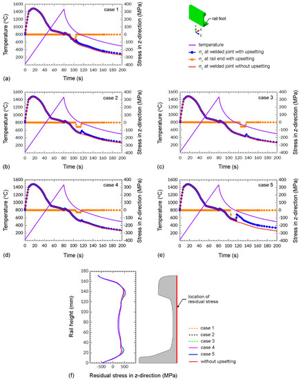
Figure 13.
Stresses in the longitudinal direction of the welded joint under various ranges of upsetting temperature and upsetting forces, (a) case 1: 1025 to 860 °C/450 kN, (b) case 2: 880 to 780 °C/450 kN, (c) case 3: 755 to 690 °C/450 kN, (d) case 4: 880 to 780 °C/225 kN, (e) case 5: 880 to 780 °C/900 kN, and (f) comparison of the residual stresses under various upsettings.
In the investigated range of upsetting temperatures, the yield stress ranges for rail steel in cases 1 to 3 are 48 to 117 MPa, 108 to 156 MPa, and 168 to 199 MPa, respectively. Comparatively, the applied compressive stress during the upsetting process is approximately 60 MPa. As this applied compressive stress magnitude is significantly lower than the yield stress range of rail steel at 755 to 690 °C (i.e., case 3), it suggests that the additional deformation from the upsetting process is likely to be within the elastic deformation range. Consequently, the decrease in compressive stress is completely relieved upon unloading of the upsetting force (Figure 13c). However, for the upsetting temperatures of 1025 to 860 °C and 880 to 780 °C (i.e., cases 1 and 2, respectively), the yield stresses of rail steel are significantly lower than those of case 3. In this scenario, the magnitude of the applied compressive stress during the upsetting process closely compares to the yield stresses of rail steel. Thus, the influence of plastic deformation becomes noticeable, resulting in slightly lower compressive stresses in the welded joints with upsetting compared to that without upsetting (Figure 13a,b).
At the weld surface, the residual stresses in the longitudinal direction were numerically calculated, as shown in Figure 13f. The stresses of the flash-butt welded joint without upsetting were also included in the figure for comparison. Although the upsetting at temperature ranges of 1025 to 860 °C and 880 to 780 °C (i.e., cases 1 and 2) result in slightly lower compressive stresses in welded joints compared to that without upsetting (Figure 13a,b), these differences diminish as the cooling temperature decreases. Eventually, at the end of the cooling process (i.e., 25 °C), the residual stresses in the welded joints with and without upsetting are nearly identical, particularly at the rail foot and the rail head. Therefore, the ranges of upsetting temperature employed (cases 1, 2, and 3) insignificantly influence the formation of residual stress.
3.4.2. Upsetting Force
To explore the influence of the upsetting force on the development of residual stress in the upsetting temperature range of 880 to 780 °C, different upsetting forces were chosen (i.e., case 2: 450 kN, case 4: 225 kN, and case 5: 900 kN). The longitudinal stresses (σz) at the rail foot were calculated for case 4 and case 5, and presented in Figure 13d,e, respectively. During the unloading of the upsetting force, a decrease in compressive stress is observed. The smallest decrease occurs with the lowest upsetting force of 225 kN (i.e., case 4), where the applied compressive stress during upsetting (i.e., approximately 30 MPa) is significantly lower than the yield stress of the rail steel (108 to 156 MPa). Thus, the additional deformation from the upsetting process is mainly elastic, which completely relieves upon the unloading of the upsetting force. On the other hand, the highest decrease is observed with the highest upsetting force of 900 kN (i.e., case 5). After the upsetting process of case 5, the compressive stress in the welded joints is significantly lower than those without upsetting, i.e., approximately 15% lower at a temperature of 500 °C. However, it is fully relieved before the cooling temperature reaches 25 °C.
At the weld surface, the residual stresses in the longitudinal direction of case 2, 4 and 5 were calculated, as shown in Figure 13f. By the end of the cooling process at 25 °C, the residual stresses in welded joints with and without upsettings were nearly indistinguishable, particularly at the rail foot and the rail head. Consequently, the investigated upsetting forces (i.e., cases 2, 4, and 5) have an insignificant impact on the formation of residual stress.
3.5. Discussion
Flash-butt welding is widely employed for constructing long and continuous railway lines and replacing defective rails. However, this welding method introduces residual stress into the welded joint due to varying localized temperatures and thermo-mechanical stresses. The formation mechanisms of residual stress are influenced by changes in the thermal expansion coefficient, strain, and elastic modulus of the welded joint with respect to temperature. Compressive residual stresses were found around the rail head and the rail foot, i.e., approximately −648 MPa and −495 MPa, respectively. In contrast, tensile residual stresses of approximately 165 MPa were observed at the rail web. It was observed that the investigated compressive upsetting force primarily induced plastic deformation within the welded joint, leading to minimal stress alteration. However, it was fully relieved before the cooling temperature reached 25 °C. Thus, the ranges of the investigated upsetting temperature and upsetting forces had an insignificant impact on the formation of residual stress.
As the location on the flash-butt welded joint where the fatigue crack usually nucleates [4], the compressive residual stress at the rail foot can enhance the resistance to crack opening, and consequently to the fatigue resistance. However, in the case of a large crack, the crack front may be situated in the region of tensile residual stress, specifically the upper region of the rail foot, as shown in Figure 13f. In this scenario, the tensile residual stress promotes the opening of the crack surfaces, leading to the reduction in fatigue resistance. Therefore, the results obtained from this study provide a valuable reference for assessing residual stress, conducting maintenance, and enhancing the reliability of flash-butt welded rails.
In addition to flash-butt welding, which is used to construct long and continuous railway lines, various other processes contribute to the development of residual stresses in rails. These processes include the production of rail (e.g., rolling process [23], abrasive belt rail grinding [24,25]), the improvement of rail damage resistance (e.g., laser cladding [26,27], laminar plasma discrete quenching [28]), as well as the repair of damaged rail (e.g., multi-layer laser powder deposition [29]). These thermos-mechanical processes have the potential to induce residual stress, which can impact the damage resistance of the rail [30,31,32]. Consequently, it is crucial not only to consider the residual stress induced from welding for the reliability of rails but also to account for residual stress originating from other sources. Therefore, further investigation is necessary for future research in this area.
4. Conclusions
The formation of residual stress in a flash-butt welded rail and the effect of upsetting force (including its temperature range and magnitude) were numerically investigated using the three-dimensional thermal elastic–plastic FEA. The findings are summarized as follows.
- The calculated cooling temperature at the welded joint showed excellent agreement with the measured result. From 1470 to 450 °C, the cooling temperature experienced a rapid decline in approximately 150 s. Below 450 °C, the decrease in cooling temperature slowed down, eventually reaching the ambient temperature of 25 °C after a total cooling period of 3 h;
- The patterns of residual stresses obtained from the present FEA and the measurements using the hole-drilling strain-gage method exhibited similarities. The compressive residual stresses were observed around the rail head and the rail foot, while the tensile residual stresses were observed at the rail web;
- The formation mechanisms of residual stress involved the changes in thermal expansion coefficient, strain, and elastic modulus of the welded joint with temperature. The stress in the longitudinal direction of the rail was the main contribution of the residual stress around the rail head and the rail foot;
- At the end of heating process (i.e., the peak temperature of 1470 °C), the stresses of the welded joint reached zero. However, in contrast to the stresses, the strains remained in the welded joint. This retention of strains could potentially influence the development of residual strain and residual stress throughout the subsequent cooling process;
- The decreases in thermal expansion coefficient and strain and the increase in elastic modulus with decreasing temperature were the dominant factors for the formation mechanisms of residual stress during the cooling process. The stresses around the rail head and the rail foot decreased with decreasing temperature, and became compressive residual stresses before the end of the cooling process;
- Under the investigated ranges of upsetting temperature and upsetting forces, the yield stress and hardening modulus of rail steel were extremely low. Consequently, the applied compressive upsetting force primarily induced plastic deformation in the welded joint without significantly impacting stress alteration. The residual stresses in the welded joints with and without upsetting were nearly indistinguishable at the rail foot and the rail head. Thus, the investigated ranges of upsetting temperature and upsetting forces exerted an insignificant influence on the formation of residual stress.
Author Contributions
K.T.: writing—review and editing, software, methodology, conceptualization, visualization, validation, and investigation. A.H.: methodology, visualization, resources. N.N.: writing—review and editing, software, methodology, conceptualization, visualization, validation, and investigation. C.K.: writing—original draft, methodology, conceptualization, resources, funding acquisition, supervision, and project administration. All authors have read and agreed to the published version of the manuscript.
Funding
This research was funded by the National Research Council of Thailand (grant number: N41A640152/2564), and the Thammasat Postdoctoral Fellowship (grant number: TUPD5/2566).
Data Availability Statement
The raw and processed data generated during this study will be made available upon reasonable request.
Acknowledgments
The authors would like to acknowledge the numerical and experimental support from Cheewin Buakhao.
Conflicts of Interest
The authors declare that they have no known competing financial interests or personal relationships that could have appeared to influence the work reported in this paper.
Nomenclature
| AREMA | American Railway Engineering and Maintenance-of-Way Association |
| ASTM | American Society for Testing and Materials |
| α | thermal expansion coefficient |
| c | specific heat capacity |
| E | elastic modulus |
| EH | hardening modulus |
| ε | normal strain |
| εT | thermal strain |
| εx, εy, εz | normal strains in rectangular coordinate system |
| εY | yield strain |
| εz,elastic | elastic strain in the longitudinal direction of the rail |
| εz,plastic | plastic strain in the longitudinal direction of the rail |
| FEA | finite element analysis |
| HAZ | heat affected zone |
| hc | convection coefficient |
| k | thermal conductivity |
| ν | Poisson’s ratio |
| PWHT | post-weld heat treatment |
| Q | internal heat generation rate |
| q | heat flux vector |
| ρ | density of material |
| σ | normal stress |
| σv | Von Mises stress |
| σx, σy, σz | normal stresses in rectangular coordinate system |
| σY | yield stress |
| T | temperature |
| Tα | annealing temperature |
| To | ambient temperature |
| Ts | peak temperature at fusion line |
| t | time |
| x, y, z | rectangular coordinate system |
References
- Lewis, R.; Olofsson, U. Wheel-Rail Interface Handbook; Woodhead Publishing: New Delhi, India, 2009. [Google Scholar]
- Tzanakakis, K. The Railway Track and Its Long Term Behaviour; Springer: Berlin/Heidelberg, Germany; New York, NY, USA, 2013. [Google Scholar]
- BS EN 14587-1; Railway Applications—Track—Flash Butt Welding of Rails—Part 1: New R220, R260, R260Mn and R350HT Grade rails in a Fixed Plant, in British-Adopted European Standard. British Standards Institution (BSI): London, UK, 2007.
- Ozakgul, K.; Piroglu, F.; Caglayan, O. An experimental investigation on flash butt welded rails. Eng. Fail. Anal. 2015, 57, 21–30. [Google Scholar] [CrossRef]
- Lee, S.H.; Kim, S.H.; Chang, Y.S.; Jun, H.K. Fatigue life assessment of railway rail subjected to welding residual and contact stresses. J. Mech. Sci. Technol. 2014, 28, 4483–4491. [Google Scholar] [CrossRef]
- Ma, N.; Cai, Z.; Huang, H.; Deng, D.; Murakawa, H.; Pan, J. Investigation of welding residual stress in flash-butt joint of U71Mn rail steel by numerical simulation and experiment. Mater. Des. 2015, 88, 1296–1309. [Google Scholar] [CrossRef]
- Yan, S.; Chen, H.; Gou, G.; Li, D.; Liu, Y.; Zhu, Z. Research on measurement of residual stresses in flash-butt-weld rails using X-ray diffraction. Adv. Mater. Res. 2011, 291–294, 934–940. [Google Scholar] [CrossRef]
- Ma, R.; Huang, D.; Zhang, J.; Zhang, Y.; Lv, Q. Effects of rail flash-butt welding and post-weld heat treatment processes meeting different national standards on residual stresses of welded joints. Int. J. Mater. Res. 2020, 111, 780–787. [Google Scholar] [CrossRef]
- ASTM E837-99; Standard Test Method for Determining Residual Stresses by the Hole-Drilling Strain-Gage Method, in Annual Book of ASTM Standards. ASTM International: West Conshohocken, PA, USA, 1999.
- Skyttebol, A.; Josefson, B.L.; Ringsberg, J.W. Fatigue crack growth in a welded rail under the influence of residual stresses. Eng. Fract. Mech. 2005, 72, 271–285. [Google Scholar] [CrossRef]
- Ghazanfari, M.; Tehrani, P.H. Experimental and numerical investigation of the characteristics of flash-butt joints used in continuously welded rails. Proceedings of the Institution of Mechanical Engineers. Part F J. Rail Rapid Transit 2020, 234, 65–79. [Google Scholar] [CrossRef]
- Ghazanfari, M.; Tehrani, P.H. Investigation of residual stress and optimization of welding process parameters to decrease tensile residual stress in the flash butt welded UIC60 rail. Mech. Based Des. Struct. Mach. 2020, 50, 1580–1594. [Google Scholar] [CrossRef]
- Haibatollahi, S.P.; Tehrani, P.H. Prediction of residual stress distribution in flash butt welded rails using electro-thermo-mechanical simulation. Int. J. Veh. Struct. Syst. 2013, 5, 53–57. [Google Scholar] [CrossRef]
- Tawfik, D.; Kirstein, O.; Mutton, P.J.; Chiu, W.K. Verification of residual stresses in flash-butt-weld rails using neutron diffraction. Phys. B Condens. Matter 2006, 385–386, 894–896. [Google Scholar] [CrossRef]
- Tawfik, D.; Mutton, P.J.; Chiu, W.K. Modifying residual stress levels in rail flash-butt welds using localised rapid post-weld heat treatment and accelerated cooling. Int. Heat Treat. Surf. Eng. 2008, 2, 839–848. [Google Scholar] [CrossRef]
- Pereira, H.B.; EEcheverri, A.A.; Alves, L.H.D.; Goldenstein, H. Evaluation of the effect of heat input and cooling rate of rail flash-butt welding using finite element method simulation. Soldag. E Insp. 2022, 27, e2701. [Google Scholar] [CrossRef]
- BS EN 13674-1; Railway Applications—Track—Vignole Railway Rails 46 kg/m and above, in British-Adopted European Standard. British Standards Institution (BSI): London, UK, 2002.
- Manual for Railway Engineering; American Railway Engineering and Maintenance-of-Way Association: Chicago, IL, USA, 2010; Available online: https://pdfcoffee.com/manual-for-railway-engineering-structures-pdf-free.html (accessed on 1 January 2023).
- Cai, Z.; Nawafune, M.; Ma, N.; Qu, Y.; Cao, B.; Murakawa, H. Residual stresses in flash butt welded rail. Trans. Join. Weld. Res. Inst. 2011, 40, 79–87. [Google Scholar]
- Dowling, N.E. Mechanical Behavior of Materials: Engineering Methods for Deformation, Fracture, and Fatigue; Prentice-Hall International: Sicklerville, NJ, USA, 1993. [Google Scholar]
- Bhatti, A.A.; Barsoum, Z.; Murakawa, H.; Barsoum, I. Influence of thermo-mechanical material properties of different steel grades on welding residual stresses and angular distortion. Mater. Des. 2015, 65, 878–889. [Google Scholar] [CrossRef]
- ABAQUS User’s Manual; ABAQUS Inc.: Palo Alto, CA, USA, 2016; Available online: http://130.149.89.49:2080/v6.11/pdf_books/CAE.pdf (accessed on 1 January 2023).
- Żak, S.; Wozniak, D. The influence of changes in roll pass design on the state of residual stresses in raIlway raIls—summary. Arch. Metall. Mater. 2023, 68, 439–446. [Google Scholar]
- Zhao, C.; Li, J.; Fan, W.; Liu, Y.; Wang, W. Experimental and simulation research on residual stress for abrasive belt rail grinding. Int. J. Adv. Manuf. Technol. 2020, 109, 129–142. [Google Scholar] [CrossRef]
- Wang, W.; Li, J.; Wu, Y.; Fan, W. Experimental and simulation investigation into residual stress for rail grinding with abrasive belt. Diam. Abras. Eng. 2020, 40, 5–12. [Google Scholar]
- Kendall, O.; Abrahams, R.; Paradowska, A.; Reid, M.; Qiu, C.; Mutton, P.; Schläfer, T.; Yan, W. Influence of multi-layer laser cladding depositions and rail curvature on residual stress in light rail components. Eng. Fail. Anal. 2023, 150, 107330. [Google Scholar] [CrossRef]
- Roy, T.; Paradowska, A.; Abrahams, R.; Law, M.; Mutton, P.; Soodi, M.; Yan, W. Residual stress in laser cladded heavy-haul rails investigated by neutron diffraction. J. Mater. Process. Technol. 2020, 278, 116511. [Google Scholar] [CrossRef]
- Wang, K.; Ma, Q.; Xu, J.; Liao, T.; Wang, P.; Chen, R.; Qian, Y.; Li, L. Effect of material non-uniformity and residual stress on wear and transient rolling contact behaviour in laminar plasma quenched (LPQ) rails. Wear 2023, 523, 204767. [Google Scholar] [CrossRef]
- Mortazavian, E.; Wang, Z.; Teng, H. Finite element investigation of residual stresses during laser powder deposition process as an innovative technique to repair worn rails. Proceedings of the Institution of Mechanical Engineers. Part F J. Rail Rapid Transit 2023, 237, 21–32. [Google Scholar] [CrossRef]
- Fang, X.Y.; Zhang, H.N.; Ma, D.W.; Wu, Z.J.; Huang, W. Influence of welding residual stress on subsurface fatigue crack propagation of rail. Eng. Fract. Mech. 2022, 271, 108642. [Google Scholar] [CrossRef]
- Kang, C.; Wenner, M.; Marx, S. Experimental investigation on the rail residual stress distribution and its influence on the bending fatigue resistance of rails. Constr. Build. Mater. 2021, 284, 122856. [Google Scholar] [CrossRef]
- Liu, Y.; Tsang, K.S.; Subramaniam, N.A.; Pang, J.H.L. Structural fatigue investigation of thermite welded rail joints considering weld-induced residual stress and stress relaxation by cyclic load. Eng. Struct. 2021, 235, 112033. [Google Scholar] [CrossRef]


Disclaimer/Publisher’s Note: The statements, opinions and data contained in all publications are solely those of the individual author(s) and contributor(s) and not of MDPI and/or the editor(s). MDPI and/or the editor(s) disclaim responsibility for any injury to people or property resulting from any ideas, methods, instructions or products referred to in the content. |
© 2023 by the authors. Licensee MDPI, Basel, Switzerland. This article is an open access article distributed under the terms and conditions of the Creative Commons Attribution (CC BY) license (https://creativecommons.org/licenses/by/4.0/).