Abstract
In this study, a lightweight fiber-reinforced plastic (FRP) helical gear was fabricated to investigate the potential application of FRP in automobile parts that require high loads and reduced noise. High-performance aramid FRP processed using the wet-laid method was used in the tooth region, and SCR420 steel was used in the inner hub region. A hot-forming system that combines rapid induction heating and water channel cooling methods was developed to reduce the cycle time. The cooling water flow conditions were analyzed to precisely control the mold temperature. Additionally, a rotating extraction system was developed to mitigate the extraction difficulty owing to the helix angle to the extraction direction. Using the innovative hot-forming system developed in this study, a helical gear without any process-induced defects was fabricated with a significantly reduced cycle time. The performance of the gear was successfully estimated using gear durability, torsional strength, and motion noise tests. The use of FRP materials offers significant potential to realize lightweight components; however, certain challenges related to their properties that may limit their application must be addressed on a case-by-case basis.
1. Introduction
Fiber-reinforced polymer (FRP) composites have been used in many structural applications because of their exceptional strength-to-weight ratios. Composites have successfully replaced several conventional materials, such as wood and metal, in various engineering fields, including aerospace, shipbuilding, automotive, and military fields, owing to their high specific strength, rigidity, and low density.
FRP composites are manufactured by integrating fibrous reinforcements and a polymeric matrix using the mixed-curing-agent-assisted layer-by-layer processing method [1,2]. FRPs can be classified as carbon, aramid, and hybrid fiber types. The static properties, such as the elastic modulus and strength-to-weight ratio, of the carbon fiber type are superior to those of the other categories [3,4,5]. In contrast, compared to the others, the aramid fiber type has superior dynamic properties, such as the impact resistance, with a comparable density [6,7].
Emissions from various industries have emerged as a global environmental concern. As a result, car manufacturers are producing vehicles that emit less pollution than earlier automobile models [8,9]. Recently, research on various eco-friendly vehicles, such as hybrid electric, electric, and fuel-cell electric vehicles, has been actively conducted [10]. Changes to the current drive systems, such as the application of a high-efficiency transmission and battery system, inevitably increase the weight of the vehicle body; therefore, a practical strategy is required for weight reduction. The use of FRP offers significant potential for realizing lightweight components.
Automakers have produced small gear parts by using engineering plastics, but their low strength level makes them unsuitable for use in drive gears for powertrains [11]. In the case of composite gears, the deformation is relatively small compared to steel and plastic materials [12]. The demand for power-transmitting gears, including those used in engine parts and speed reduction parts that control the rotational speed of the driving parts, is expected to increase in the near future owing to the advent of eco-friendly vehicles [11]. Because of the nature of the drive system, the manufacture of parts using materials with high noise and vibration attenuation is essential to improve the driving sensibility [13].
Therefore, the application of lightweight FRP to helical gears with helix angles, which are complex parts of the powertrain driving gear, is expected to facilitate the further application of FRP in automobile parts that require high loads and reduced noise.
Metal-FRP hybrid components have attracted increasing attention owing to their unique advantages, including light weight and high performance, ductility, and strength. Therefore, an innovative technology was developed in this study to fabricate FRP helical gears with a steel insert. High-performance FRP was used in the highly stressed tooth region, and steel was used in the inner hub region. The helical gears were manufactured via the wet-laid method using FRP composed of aramid material.
The wet-laid method is similar to the conventional papermaking process; however, it involves wet material processing using chopped synthetic fibers instead of natural cellulose fibers. Consequently, it has attracted significant research attention as an advantageous process for manufacturing high-grade non-woven composite sheets [14]. Compared to other methods, the wet-laid method helps achieve a higher fiber density, rendering it possible to manufacture high-strength composite materials.
Wet-laid composite materials are known to possess superior mechanical properties, including a higher damping capacity, higher impact resistance, and lighter weight, compared to conventional laminated composites [15,16]. Laminated composites have received negligible attention as potential materials for gear-drive applications.
For improved tensile and dynamic properties, FRP composites are generally fabricated using the hot-forming process [17]. Therefore, this process was applied in this study to fabricate FRP helical gears with high precision without process-induced defects.
Cartridge heating is widely used to heat the mold for FRP hot forming. Because the heating efficiency of the cartridge heater is not high, a relatively long time is required to heat the mold. Furthermore, the precise control of the mold temperature is difficult. A natural air-cooling method was used for mold cooling after FRP hot forming; therefore, a long time was required to cool the mold for the extraction of the molded parts. Considering the mass production of FRP molding, this is unfavorable in terms of productivity and cost. The increased cycle time from heating to cooling significantly reduces the process efficiency of FRP hot forming. The utilization of these FRP materials is a trend that is gradually increasing throughout the industry, but research on molding devices for implementing various molding methods according to the characteristics of materials is poor. Conventional hot forming methods have a structure in which only one system of mold heating or cooling is applied. To the best of our knowledge, a system that can significantly reduce the cycle time of FRP molding has not yet been reported.
Therefore, in this study, an innovative system that can simultaneously achieve rapid heating and cooling was developed to improve the cycle time of the existing FRP molding system.
To expedite the heating rate, a new induction heating method was applied to heat the FRP mold. Induction heating systems consist of an electromagnet and an electronic oscillator that passes a high-frequency alternating current (AC) through the electromagnet, which is installed in the FRP hot-forming system [18,19,20,21,22,23,24].
Cooling channels were installed on the inside of the mold for its rapid cooling. To precisely control the mold temperature, the water flow condition was analytically investigated. Additionally, when the FRP helical gear reaches room temperature after molding, its extraction is difficult because of the helix angle to the extraction direction. To address this issue, a rotating extraction system was utilized in this study.
Using the developed rapid heating and cooling system, an FRP helical gear, which is a key component for the power transmission of the driving system, was fabricated with a steel insert. The efficacy of the fabricated FRP helical gear was assessed using X-ray CT and precision three-dimensional (3D) measurements, and its performance was estimated using gear durability, torsional strength, and motion noise tests.
2. Experimental Procedure
2.1. Materials
The wet-laid fiber-reinforced plastic (WLF) material used in this study is composed of aramid pulp, P-aramid fiber, M-aramid fiber and phenolic resin. Aramid pulps produced by fibrillation on the surface of P-aramid fibers are used to enhance the interfacial bonding between fibers and resin [13]. Additionally, the WLF preform used in this study was manufactured through successive pulper, stirring, fixation dispensing, WLF sheet-manufacturing, dehydration, and cutting processes. The pulper process dissociates pulp-type materials and uniformly mixes the aramid pulp materials, aramid fibers, and resin. The stirring process is used to adjust the concentration of the mixed material obtained from the pulper process and obtains a homogeneous mixture before the sheet-manufacturing process. The fixation dispensing process generates cross-linking between the fibers using a fixative. The WLF sheet is manufactured by placing the material to which the fixative is administered into a mold in the form of a sheet. A dehydration process is performed to dry the moisture in the WLF sheet. The preform was manufactured by applying pressure to the dehydrated sheet material using a preform cutter. A WLF helical gear preform was then manufactured using a gear tooth-shaped cutter, as shown in Figure 1. The gear dimensions listed in Table 1 are designed based on the ISO (or former DIN 3961/62) standard.
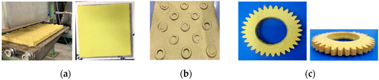
Figure 1.
(a) WLF sheet manufacturing; (b) Cutting process; and (c) WLF preform manufacturing.

Table 1.
Dimensions of the WLF preform.
The molding of the thermoset WLF preform was performed in a hot state, and the process was completed by cooling to room temperature in the mold. The starting material for making thermosets was malleable prior to curing, and was designed to be molded into the final shape. Once hardened, a thermoset cannot be melted. Therefore, the cured WLF preform can be used as a thermally stable gear because of its excellent thermal stability. As shown in Figure 2, when the mold temperature converged to the heating target temperature, dry WLF preform sheets were stacked, pressed, and cured using a temperature-controlled hot press. Additionally, when the temperature of the mold reached room temperature, the cured WLF preform was taken out. The characteristics of the cured WLF preform are listed in Table 2.
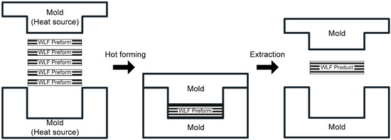
Figure 2.
Hot forming of the WLF preform.
Table 2.
Mechanical properties of the cured WLF Preform.
2.2. Steel Hub Insert
The WLF helical gear was composed of WLF material in the outer tooth region and steel in the inner hub insert coupled with the shaft. The steel hub insert was designed and manufactured and then joined with the outer WLF material, as shown in Figure 3. A taper gradient was applied to the protruding part of the steel hub insert to increase the joint strength of the two materials when a torque was applied to the WLF helical gear. The taper gradient of the protrusion had an angle of 53° with a depth of 1.5 mm. Existing steel gear material (SCR420) was used for the steel insert; its chemical composition is listed in Table 3.
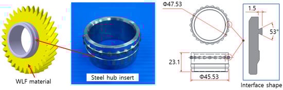
Figure 3.
Steel hub insert.
Table 3.
Chemical composition of SCR420.
2.3. Test Method
2.3.1. Gear Precision Measurement
Gear measurement equipment (KLINGELNBERG P26) was used to measure the dimensions of the WLF helical gear. The gear was mounted on the measuring instrument, and the probe was moved left and right to measure the dimensions of the gear, as shown in Figure 4. The steel helical gear, which is the object of comparison with the WLF helical gear in this study, was manufactured through the processes of forging, turning, hobbing, heat treatment, and grinding. The precision level of the steel helical gear must satisfy the AGMA 390.03 standard of 9th grade (single pitch error standard: 14 µm or less; runout error standard: 39 µm or less) or higher.

Figure 4.
(a) Schematic of gear dimension measurement; (b) Measurement device.
2.3.2. Gear Durability Test
To evaluate the lifespan of the WLF helical gear products, a hydraulic rotary actuator (MTS 215.45) with a simulated driving system was used. The test conditions required for gears developed under operating environment conditions were applied for a certain period of time to determine whether damage occurred after the durability test. A WLF helical gear was installed on the fixed jig, which was mounted on the torsion tester. The steel hub insert was fixed to the shaft of the opposite jig. Figure 5 shows the steel hub insert fixed to the shaft of the torsion tester. The durability test was performed while the shaft rotated left and right by 0.5° to 1° under the fatigue endurance conditions listed in Table 4.
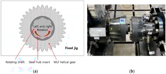
Figure 5.
(a) Schematic of the gear durability test; (b) Gear durability tester.
Table 4.
Test conditions.
2.3.3. Torsional Strength Test
Torsional strength tests were performed to measure the bond strength between the steel insert and the WLF material. Torsion testing was performed using a hydraulic rotary actuator (MTS 215.45), as shown in Figure 6. The method of mounting the WLF helical gear on the testing machine was the same as that of the gear durability tester. The shaft rotated at a test speed of 2°/min until the joint failed, and the torque was measured until that point.
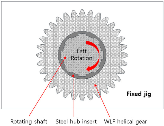
Figure 6.
Schematic of the torsional strength test.
2.3.4. Noise Measurement
In the gear rig tester for noise measurement, a spherical microphone with a diameter of 80 mm was installed at a distance of 500 mm from the front of the gear to measure and compare noise during gear operation, as shown in Figure 7. The rig tester used simulated the driving environment system and compared the noise levels in the frequency band of the gear.
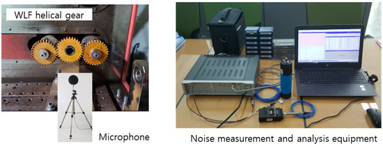
Figure 7.
Noise measurement of the WLF helical gear.
2.3.5. Inspection of Internal and External Defects in the Gear
X-ray CT non-destructive inspection was conducted to assess the internal defects of the WLF helical gears. The inspection was performed using a CT X-ray system (SHIMADZU SMX-225CT). The applied X-ray voltage was 170 kV. A visual inspection was also performed to determine external defects in the gear.
2.3.6. Measurement of the Gear Weight Reduction Ratio
To measure the weight reduction ratio of the WLF helical gear, the weight of an existing steel helical gear and the actual weight of the WLF helical gear prototype developed in this study were measured to the first decimal place with an electronic scale, and the difference was expressed as a percentage.
3. Results and Discussion
3.1. Rapid Heating and Cooling Effects
An indirect induction heating method was adopted for the uniform heating of the WLF preform [25].
Figure 8 shows the schematic of the system used for the rapid heating and cooling of the mold, wherein the mold was indirectly heated by applying a high-frequency embedded heat source. For rapid cooling, water-cooling channels were installed on the inside of the hot-forming mold. The heat of the induction-heated mold was transferred via conduction to the contact cooling channel mold and forming mold.
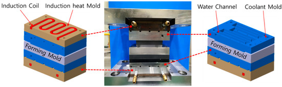
Figure 8.
Schematic of the forming mold system used for rapid heating and cooling.
In the temperature control system, the temperature detected by the mold temperature sensor was compared with the set value to control the power of the induction coil. Therefore, the target temperature could be maintained.
The developed rapid heating and cooling system and the existing cartridge heating system had the same molding time of 15 min. In this study, the material was supplied after the mold temperature converged with the target heating temperature of 160 degrees, and the material was cured during the molding time and then cooled to room temperature.
The specifications of the induction system for rapid heating are listed in Table 5.
Table 5.
Specifications of the induction system.
Based on the quantity of the heat law and fluid continuity equation, an analysis was performed to predict the cycle time during the heating and cooling processes.
To simplify the formulation involved in the analysis, the cooling water was assumed to be an incompressible, non-viscous fluid following the continuity equation of fluid.
To increase the mold temperature from room temperature (25 °C) to the target temperature (160 °C), the required amount of heat was obtained using the following formula. The specific heat of steel, , is 0.4477 J/kg∙K, and the weight of the mold, m, is 49.07 kg.
From Equation (1),
The output power of the induction heating system was set to 40 kW to raise the mold temperature to 160 °C. Considering the stability of the induction heating device, the efficiency of the existing induction heating for steel was 85%, and the performance ratio was 75%. Therefore, the actually applied induction output was obtained using Equation (2) [24].
From Equation (2), The time S for the mold to reach the target temperature of 160 °C from room temperature can be obtained from Equations (1) and (2).
From Equation (3), .
Therefore, the time required for the induction heating mold to reach 160 °C from room temperature with an output of 25.5 kW was expected to be 116 s.
The actual measured time for the induction heating mold to reach 160 °C was 124 s, which was in reasonable agreement with the analytical value. However, the recorded temperature profile shows that the mold temperature did not remain at 160 °C and rose further to 180 °C. Thereafter, the temperature decreased and converged to 160 °C. To obtain WLF material via the hot-forming process, the target temperature of 160 °C needed to be maintained during the processing time for achieving desirable WLF quality. Therefore, the time required to reach the target temperature was important when considering the cycle time.
To shorten the time to converge to a temperature of 160 °C, the mold was cooled with the amount of heat corresponding to the increased temperature.
The heat of the mold when its temperature rose from 160 to 180 °C can be obtained from Equation (1).
From Equation (1),
The mass flow rate of the cooling water in the cooling mold is as follows:
The specific heat of water is 4200 ; the density of water is 1000 ; LPM is 50; the cooling water temperature is 5 °C; and the mold temperature at the start of cooling is 140 °C. The amount of heat per unit time of the cooling mold, , is as follows:
From Equations (5) and (6),
For the water cooling of the mold, a hose with an inner diameter of 8ф and a length of 7 m was connected to the inlet and outlet. The inside of the mold had a cross section of 10 mm × 10 mm and a waterway with a length of 959.82 mm. The cooling of the mold was assumed to start after the cooling water was filled from the start of the inlet hose to the end of the outlet hose.
The time for the cooling water to reach the mold inlet from the inlet hose of the cooling system is as follows:
From Equation (7),
The time for the cooling water to reach from the inlet to the outlet of the mold is as follows:
The time for the cooling water to reach the exit end of the cooling system from the mold exit was the same as .
Therefore, the time S required for the cooling water to be filled from the start of the inlet hose to the end of the outlet hose of the water-cooling system is as follows:
The output standby time, of the water-cooling system is 2 s, and the total time can be obtained using Equation (10).
When using 5 °C cooling water, water cooling at 140 °C for 4.84 s with a flow rate of 50 LPM can suppress the temperature overshooting above 160 °C.
Therefore, the time for the temperature of the mold to converge to 160 °C was expected to be significantly shortened. As mentioned previously, the induction heating system without cooling required 300 s to converge to the FRP molding temperature (160 °C). By linking the rapid heating system and water channel cooling system, the time to converge to the FRP molding temperature (160 °C) was shortened to 3 min, as shown in Figure 9.
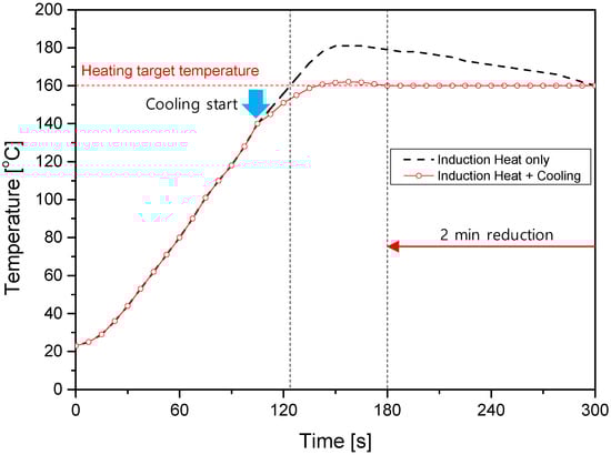
Figure 9.
Temperature profile of the rapid heating and cooling system.
The rapid cooling system pumps water from the cooling tank into the cooling channel of the cooling mold to lower the temperature of the forming mold.
The cooling rate required to cool the mold from 160 to 25 °C using 50 LPM of cooling water at 5 °C can be obtained as follows. The lower the cooling water temperature, the shorter the time required to cool the mold temperature.
From Equation (11),
From Equation (1), the amount of heat to reach the target temperature of 160 °C at room temperature is Q = 2,965,687 J. The cooling amount per unit time required to cool the mold from 160 to 25 °C at a flow speed of 50 LPM with 5 °C cooling water was 11,812 J.
From Equation (12),
Therefore, the cooling of the mold from 160 to 25 °C at a flow rate of 50 LPM with 5 °C cooling water required 251 s. In the experiments shown in Figure 10, the time required to alter the temperature from the FRP molding temperature (160 °C) to the FRP take-out temperature (25 °C) was shortened to approximately 240 s when using 5 °C cooling water. This confirms the effectiveness and reliability of rapid heating and cooling systems.
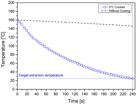
Figure 10.
Cooling temperature profile of the rapid heating and cooling system.
3.2. Preform Input and WLF Helical Gear Extraction System
To manufacture helical gear parts, an input system that simultaneously loads and compresses FRP preforms was required. Figure 11 shows the input system used to load the FRP material. The cam-gear-shaped punch mold was lowered, and the WLF preforms were stacked along the inside of the cam-gear-shaped injection mold and compressed into a helical mold.
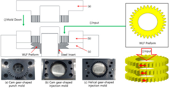
Figure 11.
Input system to load the FRP material.
The molded WLF helical gear was difficult to extract because of the helix angle to the extraction direction. The extraction cylinder of the lower frame raised the lower guide punch, which was in contact with the insert part fastened with the FRP material. The lower guide punch, which was placed in a free state at the tip of the bearing, was lifted and rotated along the helical mold based on the center of the FRP helical gear. Figure 12 shows the extraction system developed for easy extraction. As a result of smooth extraction, no breakage of the gear teeth was observed.
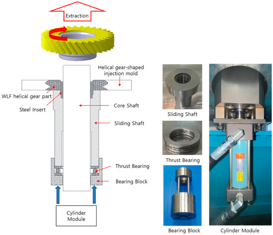
Figure 12.
Principle of WLF helical gear extraction.
3.3. Fabrication of WLF Helical Gears
The WLF helical gear was fabricated by applying the rapid heating and cooling system developed in this study. The WLF helical gear preforms were manufactured in the shape of a gear tooth, as shown in Figure 13. Table 6 lists the molding conditions of the preform.
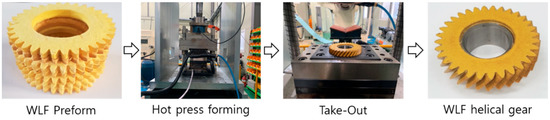
Figure 13.
Fabrication of the WLF helical gear.
Table 6.
Molding conditions of the WLF helical gear.
Aramid FRP processed using the wet-laid method was used in the tooth region, and SCR420 steel was used in the inner hub region. A hot-forming system that combines rapid induction heating and water channel cooling methods was used to reduce the cycle time. To ensure the dimensional accuracy and good degassing, the dimensional tolerance of the mold was set at 0.02 mm. A split mold was designed to facilitate the extraction of the compressed FRP molded product. The molding time was further reduced by applying an advanced extraction system. Figure 14 shows the WLF helical gear fabricated in this study.
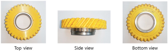
Figure 14.
Fabricated WLF helical gear.
3.4. Performance Evaluation
3.4.1. Performance of the WLF Helical Gear
Figure 15a shows an X-ray CT image of the WLF helical gear with no internal defects after gear durability test. The visual inspection of the outer surface of the WLF helical gear did not reveal any significant external defects after gear durability test as shown in Figure 15b. Based on the weight measurements, the WLF helical gear was 74.77% lighter than an existing steel helical gear with the same dimensions.
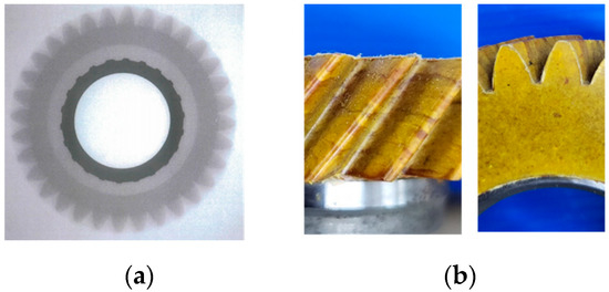
Figure 15.
(a) Internal X-ray CT image; (b) Visual inspection of the external surface.
The results obtained from gear measurement equipment (KLINGELNBERG P26) are shown in Figure 16. The measurement of the dimensions of the WLF helical gear revealed that the single pitch error at left and right flanks were 10.1 µm and 11.2 µm, respectively, and the runout error was 11.6 µm. This satisfies a single pitch error standard of 14 µm or less and a runout error standard of 39 µm or less for existing steel helical gears.
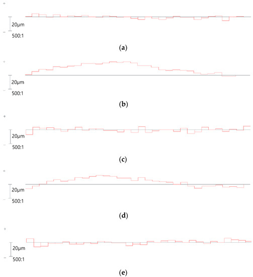
Figure 16.
Gear precision measurement results: (a) Tooth to tooth spacing fp, left flank; (b) Index Fp, left flank; (c) Tooth to tooth spacing fp, right flank; (d) Index Fp, right flank and (e) Runout Fr.
After 100,000 cycles of the durability testing of the WLF helical gear, no abnormalities were detected via visual inspection. This implies that the WLF helical gear had an acceptable rotational ability in the facility. In the torsional strength test, the damage occurred between the helical-shaped WLF material part and steel hub insert part at a torsional rotation angle of 2.5°, as shown in Figure 17. The damage strength was measured at 880.87 N·m, which is the data of the maximum inflection point of the graph. When applying the WLF helical gear to the driving parts, the current results were considered as engineering data.
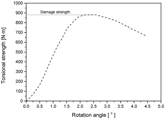
Figure 17.
Torsional strength test result graph for WLF helical gear.
The noise associated with the WLF helical gear showed a decrease of 5.4 dB compared to that of the existing steel helical gear.
Table 7 compares the results of the performance tests between the WLF helical gear and the conventional helical gear.
Table 7.
Performance results of the WLF helical gear.
3.4.2. Mold Heating and Cooling Performance of the Proposed Rapid Heating and Cooling System
The developed rapid heating and cooling system was able to rapidly heat the mold at a speed improved by 85% over that of cartridge heating to the target temperature of 160 °C via induction heating. Additionally, after molding the WLF helical gear, the mold could be rapidly cooled at a speed improved by 90% over that of natural cooling to the target temperature of 25 °C via water channel cooling. A comparison of the cycle time of the two systems is presented in Figure 18 and Table 8.
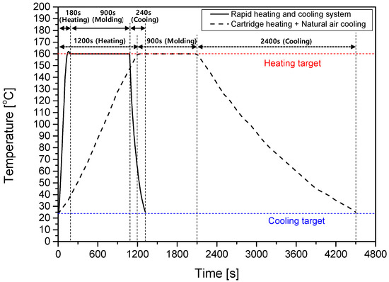
Figure 18.
Heating and cooling graphs for two systems.
Table 8.
Comparison of heating time (to 160 °C) and cooling time (to 25 °C).
In this study, a helical gear without any process-induced defects was successfully fabricated using wet-laid fiber-reinforced plastic (WLF) material through a hot-forming system that combines rapid induction heating and water channel cooling methods. The cycle time of the WLF molding process was significantly reduced. The WLF helical gear satisfied the gear precision and gear durability test standards required for steel helical gears. Additionally, WLF helical gears were superior to steel helical gears in terms of noise reduction and light weight.
4. Conclusions
In this study, a fiber-reinforced plastic helical gear was manufactured using a rapid heating and cooling system, and the main findings can be summarized as follows:
- The developed induction heating and water channel cooling system rapidly heated and cooled the mold and significantly reduced the cycle time of the hot molding process. The time required to reach the target temperature (160 °C) from room temperature can be reduced up to 85% when compared to a conventional cartridge heating system.
- Based on the quantity of heat law and fluid continuity equation, an analytical model was successfully developed to predict the time required for heating and cooling under the given temperature conditions. This analytical model is useful for setting the conditions suitable to achieve the target temperature of the system and provides results similar to the experimental values.
- The performance evaluation test confirmed that the WLF helical gear fabricated by applying FRP exhibits rotational ability in the facility. Compared with existing steel helical gears, it has an excellent weight reduction effect and an improved noise reduction effect.
- Using the as-developed rapid heating and cooling and helical gear extraction systems, high-quality WLF helical gears can be manufactured with significantly reduced costs and short cycle times.
- The metal-FRP hybrid is a practical alternative to steel in various applications. To mitigate the weakness of metal-FRP hybrids, a tailored combination of metal and FRP is required to adjust the part performance and manufacturing cost.
Author Contributions
Conceptualization, C.H.L. and Y.H.M.; Methodology, D.K.K.; Validation, C.H.L. and Y.K.K.; Investigation, C.H.L. and S.H.K.; Writing—Original Draft Preparation, C.H.L.; Writing—Review and Editing, Y.H.M.; Funding Acquisition, Y.H.M. All authors have read and agreed to the published version of the manuscript.
Funding
This work was supported by the Korea Basic Science Institute (National Research Facilities and Equipment Center) grant funded by the Ministry of Education (grant no. 2021R1A6C101A449).
Data Availability Statement
Data sharing not applicable.
Conflicts of Interest
The authors declare no conflict of interest.
Nomenclature
| Cross sectional area, m2 | |
| Efficiency of the induction system | |
| Performance ratio of the induction heating device | |
| Specific heat, J/kg∙K | |
| Diameter of the cooling hose, mm | |
| Mold weight, kg | |
| Weight flow, kg/s | |
| Liter per minute, L/min | |
| Density, kg/m3 | |
| Induction output, kW | |
| Actual applied induction output, kW | |
| Quantity of heat, J | |
| Quantity of heat per unit time, J/s | |
| Cooling time, s | |
| Start temperature, °C | |
| Target temperature, °C | |
| Fluid speed, m/s |
References
- Luan, C.; Movva, S.; Wang, K.; Yao, X.; Zhang, C.; Wang, B. Towards next-generation fiber-reinforced polymer composites: A perspective on multifunctionality. Funct. Compos. Struct. 2019, 1, 042002. [Google Scholar] [CrossRef]
- Jang, J.; Jeon, S.Y.; Choi, J.H.; Shim, W.; Cho, J.M.; Yoon, S.J.; Yu, W.R. Mechanical analysis of fiber-reinforced plastics using an elastoplastic-damage constitutive equation considering asymmetric material behavior. Compos. Struct. 2021, 272, 114268. [Google Scholar] [CrossRef]
- Sharma, M.; Gao, S.; Mäder, E.; Sharma, H.; Wei, L.Y.; Bijwe, J. Carbon fiber surfaces and composite interphases. Compos. Sci. Technol. 2014, 102, 35–50. [Google Scholar] [CrossRef]
- Davis, D.C.; Wilkerson, J.W.; Zhu, J.; Hadjiev, V.G. A strategy for improving mechanical properties of a fiber reinforced epoxy composite using functionalized carbon nanotubes. Compos. Sci. Technol. 2011, 71, 1089–1097. [Google Scholar] [CrossRef]
- Jia, Z.; Li, T.; Chiang, F.P.; Wang, L. An experimental investigation of the temperature effect on the mechanics of carbon fiber reinforced polymer composites. Compos. Sci. Technol. 2018, 154, 53–63. [Google Scholar] [CrossRef]
- Carrillo, J.G.; Gamboa, R.A.; Flores-Johnson, E.A.; Gonzalez-Chi, P.I. Ballistic performance of thermoplastic composite laminates made from aramid woven fabric and polypropylene matrix. Polym. Test. 2012, 31, 512–519. [Google Scholar] [CrossRef]
- Seretis, G.V.; Kostazos, P.K.; Manolakos, D.E.; Provatidis, C.G. On the mechanical response of woven para-aramid protection fabrics. Compos. Part B Eng. 2015, 79, 67–73. [Google Scholar] [CrossRef]
- Sanitthangkul, J.; Ratsamewongjan, A.; Charoenwongmitr, W.; Wongkantarakorn, J. Factors affecting consumer attitude toward the use of eco-car vehicles. Procedia-Soc. Behav. Sci. 2012, 40, 461–466. [Google Scholar] [CrossRef]
- Xu, G.; Miwa, T.; Morikawa, T.; Yamamoto, T. Vehicle purchasing behaviors comparison in two-stage choice perspective before and after eco-car promotion policy in Japan. Transp. Res. Part D Transp. Environ. 2015, 34, 195–207. [Google Scholar] [CrossRef]
- Lee, H.; Kim, K.; Kim, N.; Cha, S.W. Energy efficient speed planning of electric vehicles for car-following scenario using model-based reinforcement learning. Appl. Energy 2022, 313, 118460. [Google Scholar] [CrossRef]
- Kim, H.; Kim, C.; Kim, S.; Kim, B.; Lim, C. Novel steel and aramid/phenol composite gear for a transmission with optimum design and FEM vibration analysis. Int. J. Automot. Technol. 2019, 20, 749–754. [Google Scholar] [CrossRef]
- Rajeshkumar, S.; Manoharan, R. Design and analysis of composite spur gears using finite element method. Mater. Sci. Eng. 2017, 263, 062048. [Google Scholar] [CrossRef]
- Sim, E.; Kim, C.; Kwak, K.S.; Kim, B. Optimum interface shape and vibration test for a new transmission helical gear composed of steel and aramid/phenol composite. J. Mech. Sci. Technol. 2020, 34, 1629–1634. [Google Scholar] [CrossRef]
- Kim, C.; Yun, M.G.; Kim, S.; Jeon, G.W. Mathematical Model to Predict the Moduli of Wet-Laid Pulp/Fiber/Resin Composite Materials. Int. J. Precis. Eng. Manuf. 2022, 23, 1315–1324. [Google Scholar] [CrossRef]
- Hubbe, M.A.; Koukoulas, A.A. Wet-laid nonwovens manufacture–chemical approaches using synthetic and cellulosic fibers. BioResources 2016, 11, 5500–5552. [Google Scholar] [CrossRef]
- Halpin, J.C. Stiffness and expansion estimates for oriented short fiber composites. J. Compos. Mater. 1959, 3, 732–734. [Google Scholar] [CrossRef]
- Feng, Q.P.; Shen, X.J.; Yang, J.P.; Fu, S.Y.; Mai, Y.W.; Friedrich, K. Synthesis of epoxy composites with high carbon nanotube loading and effects of tubular and wavy morphology on composite strength and modulus. Polymer 2011, 52, 6037–6045. [Google Scholar] [CrossRef]
- Song, M.C.; Moon, Y.H. Coupled electromagnetic and thermal analysis of induction heating for the forging of marine crankshafts. Appl. Therm. Eng. 2016, 98, 98–109. [Google Scholar] [CrossRef]
- Merklein, M.; Wieland, M.; Lechner, M.; Bruschi, S.; Ghiotti, A. Hot stamping of boron steel sheets with tailored properties: A review. J. Mater. Process. Technol. 2016, 228, 11–24. [Google Scholar] [CrossRef]
- Francesco, G.; Giuseppina, A.; Luigino, F. Incremental forming with local induction heating on materials with magnetic and non-magnetic properties. Procedia Eng. 2017, 183, 143–148. [Google Scholar] [CrossRef]
- Sun, Y.; Wang, Y.; Yang, X.; Pang, L. A novel coil distribution for transverse flux induction heating. Phys. Procedia 2013, 50, 32–37. [Google Scholar] [CrossRef]
- Mori, K.I.; Bariani, P.F.; Behrens, B.A.; Brosius, A.; Bruschi, S.; Maeno, T.; Yanagimoto, J. Hot stamping of ultra-high strength steel parts. CIRP Ann. 2017, 66, 755–777. [Google Scholar] [CrossRef]
- Wang, Z.; Liu, P.; Xu, Y.; Wang, Y.; Zhang, Y. Hot stamping of high strength steel with tailored properties by two methods. Procedia Eng. 2014, 81, 1725–1730. [Google Scholar] [CrossRef]
- Bariani, P.F.; Bruschi, S.; Ghiotti, A.; Turetta, A. Testing formability in the hot stamping of HSS. CIRP Ann. 2008, 57, 265–268. [Google Scholar] [CrossRef]
- Kim, D.K.; Woo, Y.Y.; Park, K.S.; Sim, W.J.; Moon, Y.H. Advanced induction heating system for hot stamping. Int. J. Adv. Manuf. Technol. 2018, 99, 583–593. [Google Scholar] [CrossRef]


Disclaimer/Publisher’s Note: The statements, opinions and data contained in all publications are solely those of the individual author(s) and contributor(s) and not of MDPI and/or the editor(s). MDPI and/or the editor(s) disclaim responsibility for any injury to people or property resulting from any ideas, methods, instructions or products referred to in the content. |
© 2023 by the authors. Licensee MDPI, Basel, Switzerland. This article is an open access article distributed under the terms and conditions of the Creative Commons Attribution (CC BY) license (https://creativecommons.org/licenses/by/4.0/).