Abstract
High-purity titanium has been subjected to dynamic compression with a strain rate of 103 s−1 to activate and contraction twins. Electron backscatter diffraction (EBSD), transmission electron microscopy (TEM), and high-resolution TEM (HRTEM) were performed to observe the morphologies and twin boundaries of the contraction twins. The results show that twins are the predominant twinning mode, as well as the formation of twins due to the change in local stress state at the intersection region of twin variants or twin and grain boundary. The TEM and HRTEM observations reveal that (0001)‖ facets and (0001)‖ facets formed along the and twin boundaries, respectively. According to the theory of interfacial defects, the propagation of the twin boundary was discussed with (b3, 3) and (b1, ) twinning disconnections, as well as the growth process of the twin boundary.
1. Introduction
Deformation twins play an important role in the strain accommodation and strain hardening of hexagonal close-packed (hcp) metals and alloys [1,2]. The choice of the twinning systems strongly depends on the initial crystal orientation and the direction of shear [1,3]. In hcp metals, at least six types of twinning systems, including types (n = 1, 2, 3) and types (m = 1, 2, 4), have been experimentally observed [4,5,6]. Among these twinning modes, , , , and twins are activated by compressive stress along the c-axis, thus they are named contraction twins (CTs), while and twins are activated when extension applied along c-axis, which are called extension twins (ETs). Twinning occurs in the plane has been observed in all hcp metals, due to the lowest shear and simple shuffles in the plane [2,7]. It has been found that the formation and movement of basal–prismatic (B-P) facets in twin boundaries (TBs) are particularly important to the twinning growth [8,9,10,11]. Similarly, facets are also observed in and TBs. Li et al. [4] found that the facets are comprised of matrix‖twin interfaces in the twin system in deformed titanium (Ti). Zhang et al. [12] characterized the structures of TBs in cobalt, and proposed that the steps are consist of matrix‖(0002)twin and (0002)matrix‖twin interfaces. Consequently, it seems that the formation of facets is a universal characteristic of TBs in hcp metals.
In comparison with the twins, the twins have been mainly observed in zirconium (Zr) [13] and Ti [14], in which the c/a ratios are less than 1.633. The boundary structures of and twins have been studied in Zr by Morrow et al. [15]. They found that TBs form basal–pyramidal (B-Py) interfaces along the coherent TB (CTB), while TBs exhibit faceting that aligns prismatic planes with second-order pyramidal planes (P-Py) across the boundary. Recently, McCabe et al. [16] explored the facets of TBs in Ti. In addition to B-Py facets, they found six new facets and categorized them using atomic-scale transmission electron microscopy (TEM) observations. These results provide a comprehensive understanding of the TBs structure. However, these TB features are mainly observed at a low strain rate deformation, and similar investigations have scarcely been performed at a high strain rate deformation. Meanwhile, “anomalous” twinning modes, such as the twin is also experimentally observed in Ti at room temperature deformation [17,18]. However, due to TBs that are difficult to capture in TEM experiments, the atomic scale structures of TBs are still unknown.
In this work, the morphology and TBs of and CTs in high-purity Ti were experimentally studied using electron backscatter diffraction (EBSD), TEM, and high-resolution TEM (HRTEM). Dynamic compression with a strain rate of 103 s−1 was used to stimulate the CTs at room temperature. We also focus on the characterization of the TB structures of CTs at atomic scales, in order to understand the interfacial defects and growth mechanisms of their twinning processing.
2. Materials and Methods
The as-received material investigated in this work was high purity titanium (99.995%), received as a 100 mm × 100 mm × 10 mm rolled plate. The initial microstructure was composed of grains with an average size of ~14 μm. No twins appeared. The typical recrystallization texture was obtained with the c-axes inclined at ±35° from the normal direction (ND) towards the transverse direction (TD), as shown in Figure 1.
Figure 1.
Microstructure and macro-texture of the as-received material. (a) EBSD band contrast maps; (b) (0002) and pole figures measured using XRD.
Cylindrical samples, prepared with dimensions of φ 8 mm × 10 mm, were subjected to dynamic loading just once with an Instron Dynatup 8120 testing machine (Instron Inc., Norwood, MA, USA) at room temperature (293 K). The strain rate applied to the samples was estimated to be about 103 s−1. The tests were stopped at a strain of 5%, which was calculated by the reduction in sample thicknesses, as ε = (L0 − Ld)/L0, where L0 and Ld were the initial and final thickness of the deformed sample, respectively. More detailed information about the deformation processing has been described in [5,19]. A solid lubricant was employed during deformation to reduce the frictional effects.
After deformation, the center of cross-section of the deformed sample was mechanically ground followed by 400, 800, 1200, 2000, and 4000 silicon carbide papers, and then electropolished in a solution of 6 ml perchloric acid, 30 ml butanol, and 64 ml methanol at 253 K with a voltage of 20 V. EBSD mapping was performed on FEI Nova400 FEG-SEM (FEI Inc., Hillsboro, OR, USA) on an area of 400 × 400 μm2 with a step size of 0.5 μm to characterize the detailed microstructure. The EBSD information was acquired with Channel 5 software. A tolerance of ±5° deviation from the axis and the angle was applied in the EBSD maps. The TEM sample was prepared using a twin-jet polisher with a 10% perchloric acid and 90% alcohol solution at 233 K with a voltage of 40 V. TEM and HRTEM investigations were performed on an FEI Tecnai F30-G2 electron microscope operated at 300 kV.
3. Results
3.1. Morphologies of CTs in Deformed Samples
Figure 2 shows the typical microstructure of the deformed sample. As shown, three types of twins were activated during deformation including ET, and and CTs, the boundaries of which are highlighted by red, blue, and yellow lines, respectively (Figure 2a). The absence of any twinning mode in a few grains indicates they are deformed by slip alone [20]. For a statistical analysis, about 275 grains have been measured to quantitatively analyze the activation of the deformation twins. The statistic results indicate that deformation twinning occurred in 171 grains and 104 grains did not form any twins. Among the 171 twinned grains, there are 55 grains containing twins, 97 grains containing twins, and 6 grains containing twins.
Figure 2.
CTs formed in the deformed sample with a thickness reduction of 5%. (a) Band contrast map highlighting the TBs; (b–d) EBSD maps of grain 1, grain 2, and grain 3 in (a), respectively.
A further study of the stimulated CTs labeled by the EBSD inverse pole figure maps shows the coexistence of and in the same grain, as shown in Figure 2b–d). In Figure 2b, one and one twin are activated in the grain, each twin spans the entire grain and divides the grain into five regions. Furthermore, similar to the ETs, CTs can also stimulate multiple twin variants in one grain. As shown in Figure 2c,d, there are two twin variants and one twin formed in each grain, respectively. The representation of twin variants can be written in simplified form using misorientation between the matrix and twins and the zone axis defining the misorientation angle. The corresponding misorientation/zone axis of the twin variants in Figure 2c are 64.2° and 63.9°, while 64.7° and 62.3° are of the twin variants in Figure 2d. Some of TBs deviated from theoretical twin misorientation (64.6°) due to dislocation pile-ups adjacent to the TBs during deformation [21].
3.2. Observations of the CT and TB Structure
The cross-sectional bright field TEM image after 5% thickness reduction is shown in Figure 3a. It can be seen that a twin band occurred in this region (the low magnification of TEM graph presented in the insert image at the upper right corner). The selected area electron diffraction (SAED) pattern taken along the zone axis confirms that the band is a CT (Figure 3b). As shown in Figure 3a, the TBs with a few dislocation pile-ups around are slightly curved, which may be owing to the local stress concentration resulting from dislocation–TB interactions [22].
Figure 3.
TEM images of a CT and TB structure. (a) A TEM graph shows the morphology of the CT; (b) SAED pattern taken along the zone axis; (c) a Fourier-filtered HRTEM graph showing the atomic structure of the TB.
To understand the atomic-scale of TB structures, a Fourier-filtered HRTEM graph of the TB, which was taken from Figure 3a, is shown in Figure 3c. The traces of (0001) basal planes, prismatic planes, pyramidal planes, and twinning planes are schematically displayed for the matrix and twin using yellow and white dotted lines crossing a center point, respectively. In Figure 3c, the actual TB consists of four CTB and three facets, which are indicated by blue and red dashed lines, respectively. Based on the plane traces analysis, the facets either align the (0001) basal planes in the matrix and the pyramidal planes in the twin or the basal planes in the twin with pyramidal planes in the matrix. Therefore, the facets along the boundary are identified as basal–pyramidal (B-Py) or pyramidal–basal (Py-B), i.e., (0001)‖ facets. Similar TB features have been observed in Zr [15] and Ti [16]. However, a close match in interplanar spacing across the facet is not believed to be essential. It is worth noting that the (0001) basal plane and the pyramidal planes are not exactly parallel to each other, they are tilted at a ~5.8° angle, which is close to the results in [16] with a 6.6° angle in the B-Py facet. This is similar to the BPs facets with a ~3.7° angle in the twins in the hcp metals [23]. Morrow et al. [15] hypothesized that configurations with minimal mismatch are preferred because they result in lower energy boundary structures. Therefore, the B-Py/Py-B facets are often observed as a component of TB, and are expected to be easy form.
3.3. Observations of CT and TB Structures
The TEM and HRTEM observations of a CT are presented and the results are shown in Figure 4. Figure 4a shows a bright field TEM image of a twin at a relatively low magnification. The twin relationship is confirmed by the SAED pattern taken along the zone axis, as shown in Figure 4b. The CT can be characterized by a 76.7° rotation about the axis. The observed SAED pattern satisfies the twinning orientation relationship.
Figure 4.
TEM images of a the CT and TB structure. (a) A TEM graph shows the morphology of the CT; (b) SAED pattern taken along the zone axis; (c) a Fourier-filtered HRTEM graph showing the atomic structure of the TB. The inset in (c) shows a six-layer facet.
HRTEM observations were conducted to study the atomic structures of the TB. Figure 4c shows a Fourier-filtered HRTEM graph of the TB, in which the interface structures can be clearly observed. The misorientation between (0001) basal plane in matrix and twin is 76.5°, which further confirms the twin relationship. For trace analysis, the (0001) basal planes, prismatic planes, pyramidal planes, and twinning planes are also schematically displayed for the matrix and twin using yellow and white dotted lines crossing a center point, respectively. It can be seen that the TB consists of three CTB and two facets, which are indicated by blue and red dashed lines, respectively. Further examination of the facets reveals the presence of B-Py/Py-B planes, i.e. (0001)‖ facets. The serrated configuration of TB is composed of (0001)‖ B-Py facets and CTB. Different from the B-Py/Py-B interfaces observed in TB, the facet of TB aligns the (0001) basal planes in the twin and the pyramidal planes in the matrix (or vice versa). The tilted angle between the (0001) basal plane and pyramidal plane is ~4.8°. Furthermore, the inset in Figure 4c shows a six-layer (0001)‖ facet.
4. Discussion
4.1. Formation of CTs
The formation of and CTs was confirmed by experimental observations and simulations in the previous research [5,17,18]. It is worth noting that CTs are always formed either in the intersection region between CTs and the grain boundaries or in the intersection regions of twin variants, as shown in Figure 1b–d. It seems that the change in local stress state at the intersection region simulates the CTs. Firstly, according to the classical twinning theory, and CTs have the same twinning shear (γ = 0.22) and shuffling parameters [1]. From this point of view, the formation conditions of and CTs are consistent. However, the experimental observations show that the activated number of CTs is much higher than the number of CTs, as shown in Figure 2a, which indicates that the formation condition of CTs are different from those of the CTs. Secondly, Molecular dynamics (MD) simulations results show that the formation energies vary substantially from 521.4 mJ/m2 for the twinning plane and 815.4 mJ/m2 for twinning plane [24]. As the formation energy of the TB is much lower than the TB, the formation of CTs is more energetically favored than the CTs. Thirdly, a high stress concentration may occur in the intersection regions of twin variants or CTs and the grain boundary, which changes the local stress state at the intersection region, leading to the formation of CTs. Therefore, the formation of CTs can not only reduce the stress concentration in the intersection regions, but also accommodate the plastic strain.
4.2. Facet Structures of and TBs
Because of the differences in twinning geometry involved, no completely universal structure features for the facets can be determined for each twinning system in hcp metals. As a consequence, the facet structures of TBs may have variances with the activation of different twinning modes. For example, the BP/PB facets are only associated with TBs [25]. The migration of BP/PB facets plays an important role in twin growth [23]. As shown in Figure 3c and Figure 4c, (0001)‖ and (0001)‖ B-Py facets are experimentally observed in and TBs, respectively. Atomistic simulations have shown that the surface energy of the (0001)‖ B-Py facet for TB and the (0001)‖ B-Py facet for TB are 629 mJ/m2 and 760 mJ/m2 [26], respectively. Because of the surface energy difference between (0001)‖ and (0001)‖ B-Py facets is relatively small, the two B-Py facets have a possible existence in the and TBs, respectively. Meanwhile, the facets are often observed in short segments connecting the CTB interfaces, to form serrated configurations, as shown in Figure 3c and Figure 4c.
According to the theory of interfacial defects, Serra et al. [27,28] studied the atomic structure of the coherent TB by computer simulation [10], and predicted that several twinning disconnections (TDs) may exist for the TB. TD is described by a dislocation b and a step of height h [29]. Combining microscopies and atomic simulations, Gong et al. [26] concluded that (b3, 3) is the elementary TD and (b1, ) is the reassembly TD, which can reassemble and form various facets. Therefore, the propagation of TBs is mediated by the subsequent glide of (b3, 3) and (b1, ) TD along the TB. Atomistic simulations were also conducted to study the energies and kinetics of (b3, 3) and (b1, ) TDs with an embedded atomic method potential for Ti, and it was found that (b3, 3) TD has the lowest energy and a relatively high mobility [26]. The schematics illustration of the facets reassembly is shown in Figure 5. When shear stress is applied to TB, on the one hand, taking (b3, 3) as the elementary TD, once the energetically favored (b3, 3) TD is nucleated, it enables gliding on the CTB, which facilitates the twin growth process or reassembles a (b6, 6) TD, as shown in Figure 5a; on the other hand, (b1, ) TD has the lowest kinetic barrier and the highest mobility [29], thus a (b1, ) disclination dipole could be nucleated at a (b3, 3) TD, resulting in the formation of one (b4, 4) TD and one (b−1, −) TD, as shown in Figure 5b. Furthermore, when the (b−1, −) TD meets with the adjacent (b3, 3) TD, a (b2, 2) TD is formed. Therefore, the B-Py facets in the TB contain misfit disclination dipoles or consist of multiple short coherent segments connected by the CTB.
Figure 5.
The schematic illustration of the facet reassembly in TB. (a) A (b3, 3) TD gliding on CTB; (b) Formation of a (b4, 4) TD due to the nucleation of a (b1, ) disclination dipole.
Another B-Py/Py-B facet was observed in the TB, where the (0001) basal planes in the twin is aligned with the pyramidal planes in the matrix, as shown in Figure 4c. For this B-Py facet, the observed tilt angle between (0001)twin and matrix is 4.8°, which indicates that the disclination dipole character existed in the facet. The disclination dipole can be decomposed into the wedge and glide components similar to the BP facet in the twin [23]. Therefore, this B-Py/Py-B interface is either straight semi-coherent with misfit disclination dipoles or serrated with short coherent segments connected by the CTB [16]. Although and CTs have different twinning modes in Ti, these conjugate twinning modes have similar characteristic facets. Thus, we rationed that the elementary TD for TB is similar to (b3, 3) TD for TB. The inset in Figure 4c shows a six-layer facet between two straight CTBs. The formation of the facet may attribute to the gliding of two (b3, 3) TDs, resulting a (b6, 6) TD. Furthermore, a (b1, ) TD dipole could also be nucleated between two (b3, 3) TDs, which facilitates the growth process of CTs during deformation. However, due to the limited number of twins activated in this work, which leads to difficulty in capturing experimental images, the atomic-scale observations of the interface defects of B-Py/Py-B facets and the mobility of (b3, 3) TD in TB need to be further investigated.
5. Conclusions
The morphologies and atomic-scale TB structures of the and CTs were observed by EBSD, TEM, and HRTEM, and the following conclusions can be drawn based on our experimental results and discussion:
- (1)
- The CTs are activated during deformation. The statistical analysis shows that CTs are the predominant twinning mode. The change in local stress state at the intersection region of twin variants or CT and grain boundary may activate the CTs.
- (2)
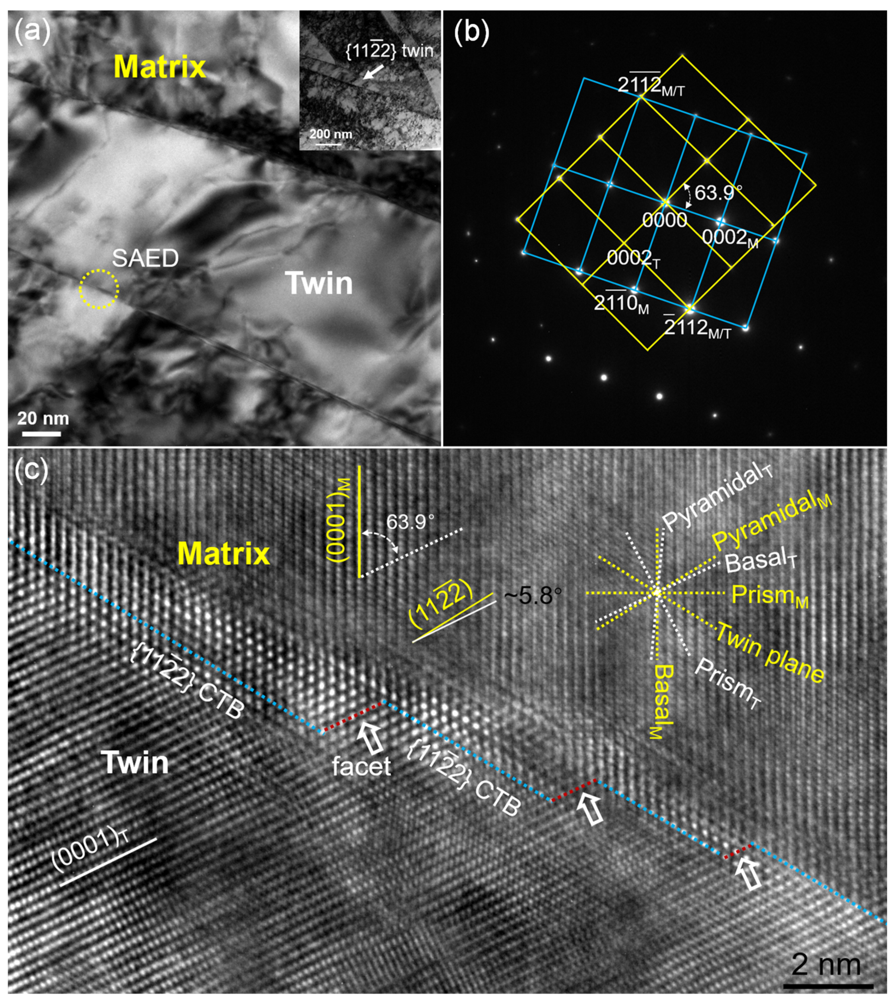
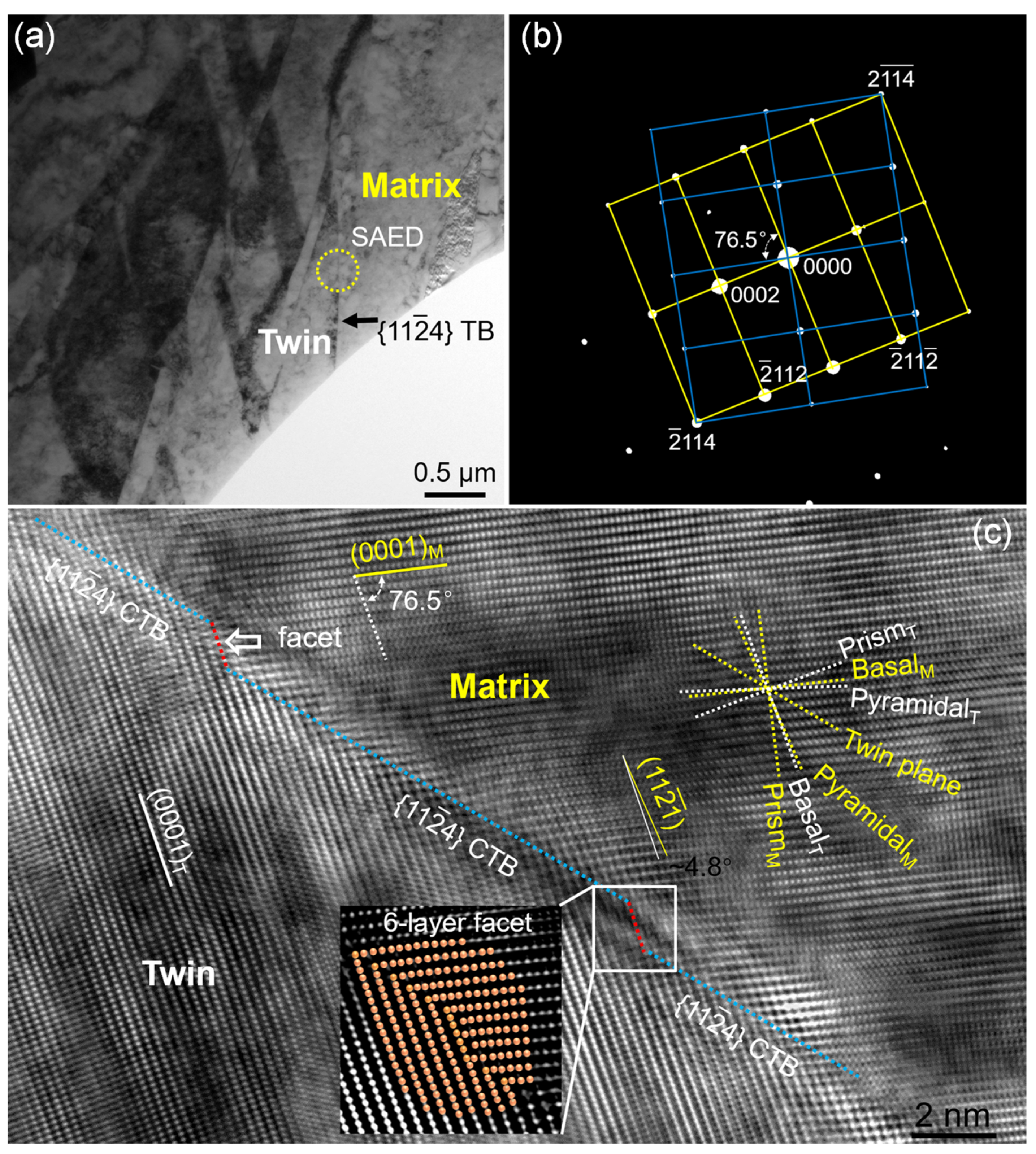
- Facets are observed in both and TBs. The (0001)‖ facet with a tilted angle of ~5.8° is observed in TBs, while the (0001)‖ facet is observed in TBs, and the tilted angle between the (0001) basal plane and pyramidal plane is ~4.8°.
- (3)
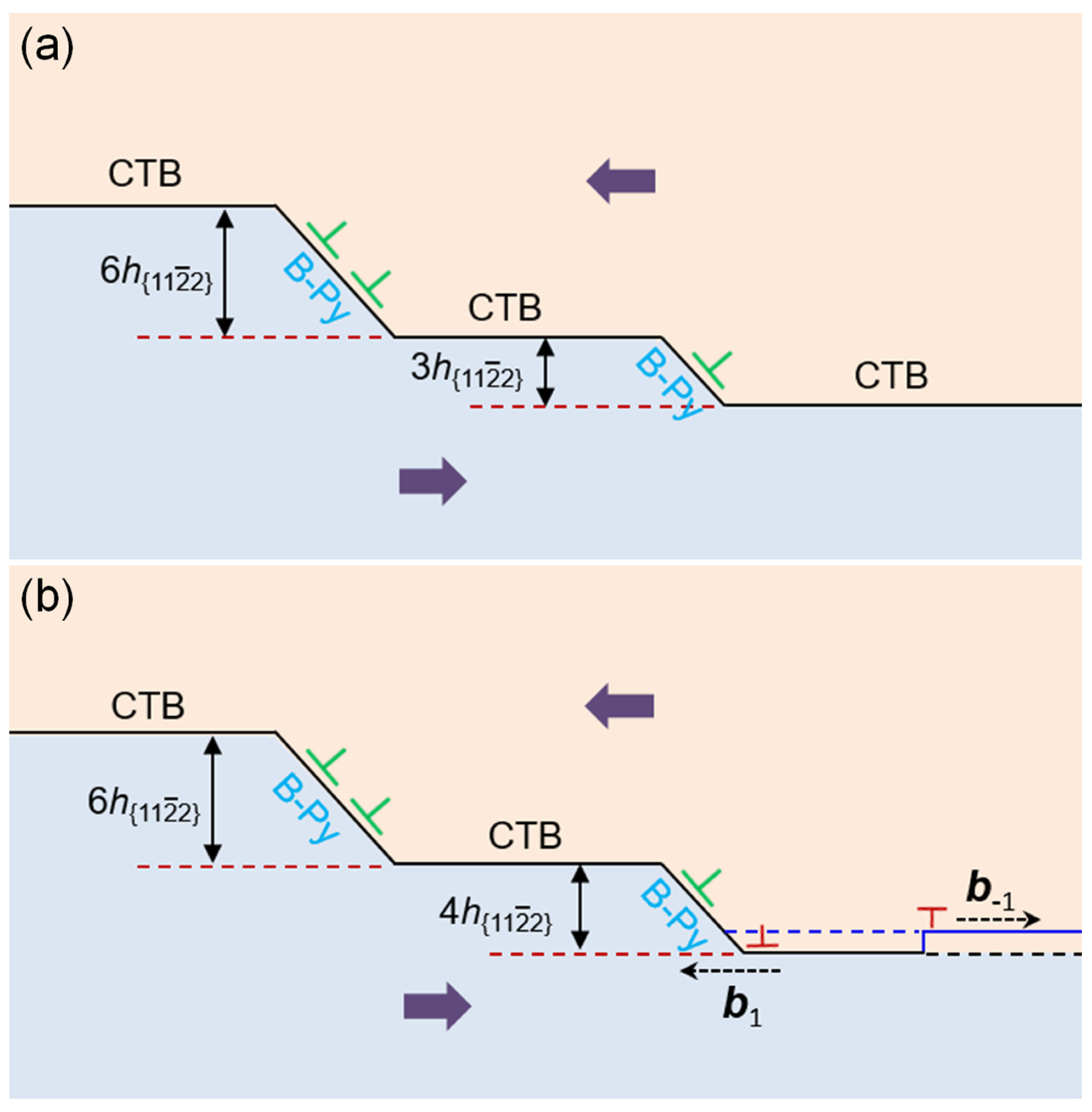
- The similar B-Py/Py-B characteristic facets are observed in both the and TB, the (b3, 3) elementary TD, and (b1, ) reassembly TD may reassemble various facets in the TB. Meanwhile, the (b3, 3) TD might be the elementary TD for the TB, which facilitates the growth process of CTs during deformation.
Author Contributions
Conceptualization, Y.R. and F.X.; methodology, C.L.; software, C.L.; validation, W.C.; investigation, F.X.; data curation, Y.R. and F.X.; writing—original draft preparation, Y.R.; writing—review and editing, Y.R. and Q.Y.; visualization, C.L.; supervision, Y.R.; project administration, Y.R.; funding acquisition, Y.R. and Q.Y. All authors have read and agreed to the published version of the manuscript.
Funding
This work was supported by the National Natural Science Foundation of China (no. 52001038), the Natural Science Foundation of Chongqing, China (no. cstc2019jcyj-msxmX0787, cstc2021jcyj-msxmX0011, and CSTB2022NSCQ-MSX0891), and the Science and Technology Research Program of the Chongqing Municipal Education Commission (grant no. KJQN201900712).
Data Availability Statement
Not applicable.
Acknowledgments
The authors thank Linjiang Chai from the School of Materials Science and Engineering, Chongqing University of Technology, for their valuable advice.
Conflicts of Interest
The authors declare no conflict of interest.
References
- Christian, J.W.; Mahajan, S. Deformation twinning. Prog. Mater. Sci. 1995, 39, 1–157. [Google Scholar] [CrossRef]
- Liao, X.Z.; Wang, J.; Nie, J.F.; Jiang, Y.Y.; Wu, P.D. Deformation twinning in hexagonal materials. MRS Bull. 2016, 41, 314–319. [Google Scholar] [CrossRef]
- Sinha, S.; Pukenas, A.; Ghosh, A.; Singh, A.; Skrotzki, W.; Gurao, N.P. Effect of initial orientation on twinning in commercially pure titanium. Philos. Mag. 2017, 97, 775–797. [Google Scholar] [CrossRef]
- Li, Y.J.; Chen, Y.J.; Walmsley, J.C.; Mathinsen, R.H.; Dumoulin, S.; Roven, H.J. Faceted interfacial structure of twins in Ti formed during equal channel angular pressing. Scr. Mater. 2010, 62, 443–446. [Google Scholar]
- Ren, Y.; Zhang, X.Y.; Xia, T.; Sun, Q.; Liu, Q. Microstructural and texture evolution of high-purity titanium under dynamic loading. Mater. Des. 2017, 126, 123–134. [Google Scholar] [CrossRef]
- Zhang, X.Y.; Zhu, Y.T.; Liu, Q. Deformation twinning in polycrystalline Co during room temperature dynamic plastic deformation. Scr. Mater. 2010, 63, 387–390. [Google Scholar] [CrossRef]
- Gengor, G.; Mohammed, A.S.K.; Sehitoglu, H. Twin interface structure and energetics in HCP materials. Acta Mater. 2021, 219, 117256. [Google Scholar]
- Tu, J.; Zhang, X.Y.; Wang, J.; Sun, Q.; Liu, Q.; Tomé, C.N. Structural characterization of twin boundaries in cobalt. Appl. Phys. Lett. 2013, 103, 051903. [Google Scholar]
- Zhang, X.Y.; Li, B.; Wu, X.L.; Zhu, Y.T.; Ma, Q.; Liu, Q.; Wang, P.T.; Horstemeyer, M.F. Twin boundaries showing very large deviations from the twinning plane. Scr. Mater. 2012, 67, 862–865. [Google Scholar] [CrossRef]
- Wang, J.; Hirth, J.P.; Tomé, C.N. Twinning nucleation mechanisms in hexagonal-close-packed crystals. Acta Mater. 2009, 57, 5521–5530. [Google Scholar]
- Yaddanapudi, K.; Leu, B.; Kumar, M.A.; Wang, X.; Schoenung, J.M.; Lavernia, E.J.; Rupert, T.J.; Beyerlein, I.J.; Mahajan, S. Accommodation and formation of twins in Mg-Y alloys. Acta Mater. 2021, 204, 116514. [Google Scholar]
- Sun, Q.; Zhang, X.Y.; Yin, R.S.; Ren, Y.; Tan, L. Structural characterization of twin boundaries in deformed cobalt. Scr. Mater. 2015, 108, 109–112. [Google Scholar] [CrossRef]
- McCabe, R.J.; Proust, G.; Cerreta, E.K.; Misra, A. Quantitative analysis of deformation twinning in zirconium. Int. J. Plast. 2009, 25, 454–472. [Google Scholar] [CrossRef]
- Barrett, C.; Martinez, J.; Nitol, M. Faceting and twin-twin interactions in and twins in titanium. Metals 2022, 12, 895. [Google Scholar]
- Morrow, B.M.; McCabe, R.J.; Cerreta, E.K.; Tome, C.N. Observations of the atomic structure of tensile and compressive twin boundaries and twin-twin interactions in Zirconium. Metall. Mater. Trans. A 2014, 45A, 5891–5897. [Google Scholar] [CrossRef]
- Wang, S.; Dang, K.; McCabe, R.J.; Capolungo, L.; Tomé, C.N. Three-dimensional atomic scale characterization of twin boundaries in titanium. Acta Mater. 2021, 208, 116707. [Google Scholar]
- Lainé, S.J.; Knowles, K.M. deformation twinning in commercial purity titanium at room temperature. Philos. Mag. 2015, 95, 2153–2166. [Google Scholar]
- Xu, F.; Zhang, X.; Ni, H.; Liu, Q. deformation twinning in pure Ti during dynamic plastic deformation. Mater. Sci. Eng. A 2012, 541, 190–195. [Google Scholar]
- Li, Y.S.; Tao, N.R.; Lu, K. Microstructural evolution and nanostructure formation in copper during dynamic plastic deformation at cryogenic temperatures. Acta Mater. 2008, 56, 230–241. [Google Scholar] [CrossRef]
- Zhang, R.; Zhao, Q.; Zhao, Y.; Guo, D.; Du, Y. Research progress on slip behavior of α-Ti under quasi-Static loading: A Review. Metals 2022, 12, 1571. [Google Scholar] [CrossRef]
- Xin, C.; Wang, Q.; Ren, J.; Zhang, Y.; Wu, J.; Chen, J.; Zhang, L.; Sang, B.; Li, L. Plastic deformation mechanism and slip transmission behavior of commercially pure Ti during in situ tensile deformation. Metals 2022, 12, 721. [Google Scholar] [CrossRef]
- Lin, T.; Chang, T.; Xie, Q.; Li, C.; Si, X.; Yang, B.; Du, Q.; Wei, D.; Qi, J.; Cao, J. Surface morphology and gradient microstructural evolutions in pure titanium via surface severe plastic deformation. Mater. Charact. 2022, 191, 112114. [Google Scholar] [CrossRef]
- Gong, M.; Hirth, J.P.; Liu, Y.; Shen, Y.; Wang, J. Interface structures and twinning mechanisms of twins in hexagonal metals. Mater. Res. Lett. 2017, 5, 449–464. [Google Scholar] [CrossRef]
- Wang, J.; Beyerlein, I.J. Atomic structures of symmetric tilt grain boundaries in hexagonal close-packed (hcp) crystals. Metall. Mater. Trans. A 2012, 43A, 3556–3569. [Google Scholar]
- Barrett, C.D.; El Kadiri, H. Fundamentals of mobile tilt grain boundary faceting. Scr. Mater. 2014, 84–85, 15–18. [Google Scholar] [CrossRef]
- Gong, M.; Xu, S.; Xie, D.; Wang, S.; Wang, J.; Schuman, C.; Lecomte, J.-S. Steps and secondary twinning associated with twin in titanium. Acta Mater. 2019, 164, 776–787. [Google Scholar]
- Serra, A.; Bacon, D.J. Modelling the motion of twinning dislocations in the HCP metals. Mater. Sci. Eng. A 2005, 400–401, 496–498. [Google Scholar]
- Ostapovets, A.; Verma, R.; Serra, A. Unravelling the nucleation and growth of twins. Scr. Mater. 2022, 215, 114730. [Google Scholar]
- Pond, R.C.; Hirth, J.P. Defects at surfaces and interfaces. Solid State Phys. 1994, 47, 287–365. [Google Scholar]
Disclaimer/Publisher’s Note: The statements, opinions and data contained in all publications are solely those of the individual author(s) and contributor(s) and not of MDPI and/or the editor(s). MDPI and/or the editor(s) disclaim responsibility for any injury to people or property resulting from any ideas, methods, instructions or products referred to in the content. |
© 2023 by the authors. Licensee MDPI, Basel, Switzerland. This article is an open access article distributed under the terms and conditions of the Creative Commons Attribution (CC BY) license (https://creativecommons.org/licenses/by/4.0/).