Abstract
Although elliptical tubes are stronger and more stable than circular tubes, few studies have fully considered the behavior of elliptical tubes under cyclic bending loads. This study experimentally investigated the response and failure of SUS304 stainless steel elliptical tubes with four different ratios of long and short axes (1.5, 2.0, 2.5, and 3.0) under cyclic bending along four different orientation angles (0°, 30°, 60°, and 90°). The wall thickness was 0.7 mm, and cyclic bending was applied until buckling failure occurred. The moment–curvature curves exhibited cyclic hardening, and stable loops were formed for all long–short axis ratios and orientation angles. Increasing the long–short axis ratio slightly decreased the peak bending moment while increasing the orientation angle increased the peak bending moment. For a given orientation angle, the curves relating the short-axis variation (i.e., change in length divided by the original length of the short axis) and curvature demonstrated symmetry, serrations, and a growth pattern as the number of cycles increased regardless of the long–short axis ratio. At long–short axis ratios of 2.0, 2.5, and 3.0, these curves even exhibited a butterfly-like trend. Increasing the long–short axis ratio increased the short-axis variation, while increasing the orientation angle decreased the short-axis variation. Regarding the curves relating the curvature and number of cycles required to initiate buckling, for each orientation angle, the four long–short axis ratios corresponded to four straight lines when plotted on double-logarithmic co-ordinates. Based on the experimental results, empirical equations are proposed to describe the above relationships. The empirical equations were applied to predicting experimental data and showed close agreement.
1. Introduction
Traditional circular tubes are commonly employed as pipes or support structures, but they exhibit limited load-bearing capacity, wear resistance, and shock absorption. Many researchers have studied the bending behavior of smooth circular tubes. Kyriakides and Shaw [1] developed a mechanical apparatus capable of conducting monotonic or cyclic bending tests on circular tubes with and without external pressure. This apparatus has been applied to studying circular tubes made from 1020 steel, 1018 steel, 304 stainless steel, 6061-T6 aluminum alloy, and NiTi circular smooth tubes (Kyriakides and Shaw [1], Corona and Kyriakides [2], Corona and Kyriakides [3], Corona et al. [4], Limam et al. [5], Limam et al. [6], Bechle and Kyriakides [7], Jiang et al. [8], Kazinakis et al. [9]). Other researchers have similarly reported relevant findings. Meanwhile, Yuan and Mirmiran [10] examined the buckling behavior of fiber-reinforced concrete-filled plastic pipes. Elchalakani et al. [11] determined the slenderness limit of a cold-formed circular hollow section featuring a fully ductile profile by conducting cyclic bending tests at varying amplitudes. Houliara and Karamanos [12] explored the in-phase bending and buckling response of circular tubes subject to external pressure. Elchalakani and Zhao [13] inspected the cyclic bending response of cold-formed concrete-filled steel tubes. Zhi et al. [14] studied the dynamic instability of cylindrical shells with a single layer under earthquake conditions. Yazdani and Nayebi [15] investigated the damage sustained by pipes subjected to periodic bending while under steady internal pressure. Guo et al. [16] studied the bending response of thin-walled circular hollow tubes. Shariati et al. [17] experimentally examined the response of SS316L cantilevered cylindrical shells under cyclic bending. Elchalakani et al. [18] established novel ductile slenderness limits for the plastic design of concrete-filled tubes based on strains observed in bending tests. Shamass et al. [19] considered the instability of circular tubes following non-proportional paths. Li and Wang [20] examined the instability of a single-layer cable-reinforced reticulated shell when subjected to seismic forces. Chegeni et al. [21] explored the impact of corrosion depth and shape on the performance of curved pipes under specific internal pressures. Jin et al. [22] explored the local buckling behavior of circular tubes with outer diameter–wall thickness ratios of 40 and 97 when subjected to axial and bending loads. Silveira et al. [23] demonstrated that the constructal law is applicable to the geometric evaluation of mechanics of materials engineering systems. They considered a symmetrical structural engineering system comprising simply supported square steel plates with a central elliptical perforation subjected to equal biaxial compressive loads. He et al. [24] proposed a corrected relationship between the bending angle and the length of the transition-section-forming zone, which they verified through free bending experiments and simulations using AA5052 tubes. Wang et al. [25] experimentally studied the bending performance of concrete-filled square steel tubes reinforced with internal steel angles using a four-point bending test. They found that the yield strength and thickness of the steel pipe had the most significant impact on the bending capacity.
Elliptical tubes offer several advantages over circular tubes including better fluid dynamics, load-bearing capacity, wear resistance, and shock absorption. For example, using elliptical tubes to support greenhouses with large spans can reduce or eliminate the number of columns required compared to using circular tubes. Elliptical tubes can be used to support fitness equipment by providing stability, strength, and resistance against shaking. Elliptical tubes can be used as table and chair legs for easy height adjustment and a strong load-bearing capacity. Elliptical tubes can also be used as transportation pipelines to transport various liquids (e.g., crude oil, gas, liquefied gas, and water) and fine and loose materials. Almost all commercially available elliptical tubes are made from SUS304 stainless steel, which offers excellent properties such as high corrosion resistance, high ductility, easy processing, and high tensile strength. Elliptical tubes are often subjected to cyclic bending loads, and their bending rigidity gradually decreases as the bending moment or number of cycles increases. This behavior is referred to as degradation for which the short-axis variation is a useful indicator. Buckling failure transpires when the short-axis variation surpasses a critical threshold. However, research on the behavior of elliptical tubes under bending loads is lacking in the literature.
This study experimentally investigated the response and failure of SUS304 stainless steel elliptical tubes subjected to cyclic bending loads. The effects of the long–short axis ratio and bending orientation on parameters including the bending moment, curvature, short-axis variation, and number of cycles required to initiate buckling were carefully measured and analyzed.
2. Experiment
2.1. Bending Device
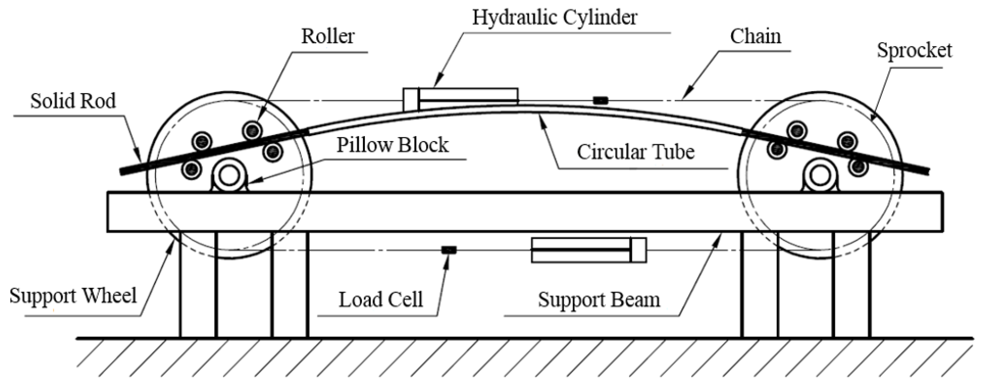
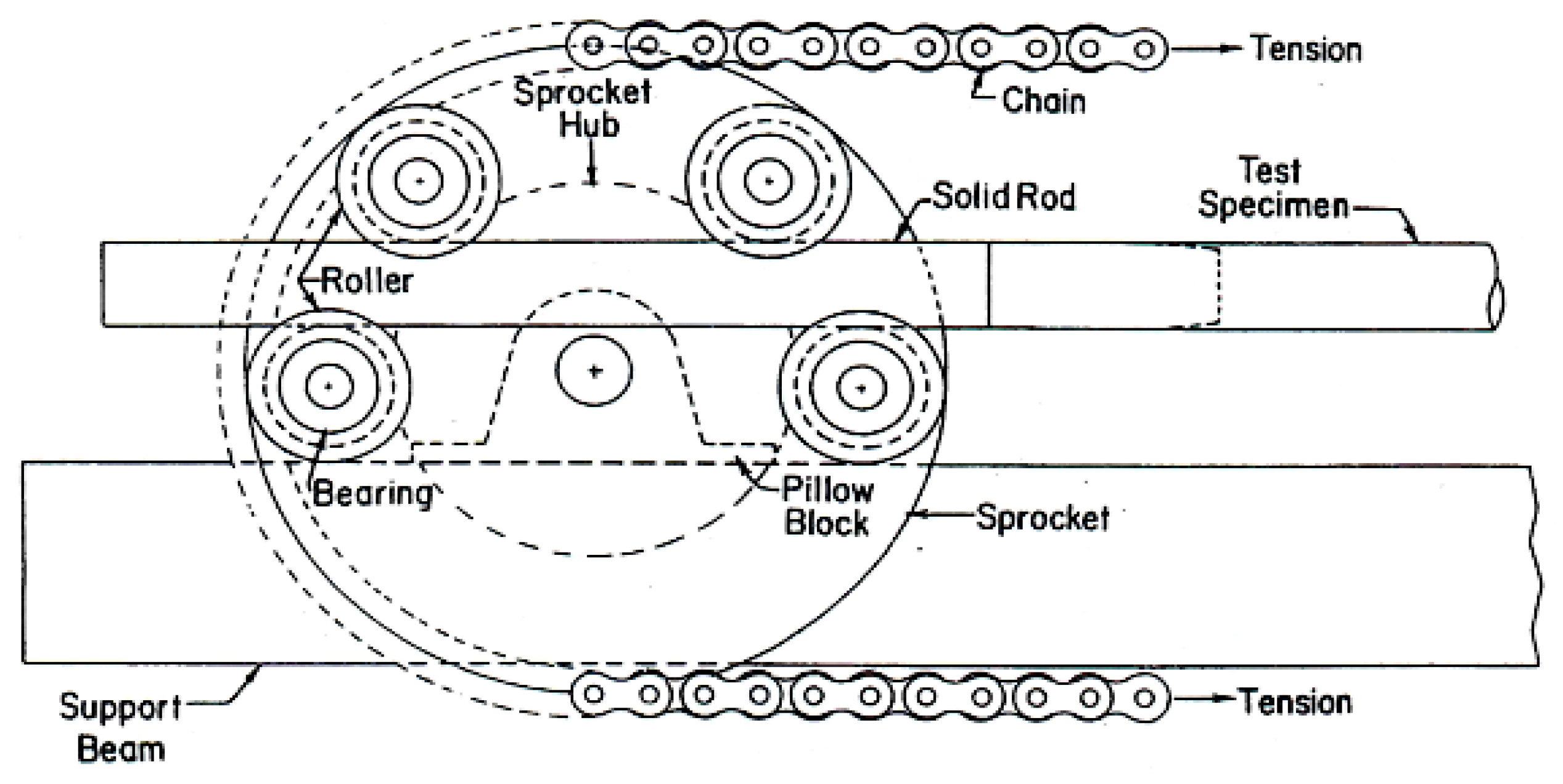
Figure 1 shows the four-point bending machine used to conduct the cyclic bending tests [26], which comprised two rotating sprockets positioned on two supporting beams. A robust chain ran around these sprockets, which were supported by heavy-duty beams. This bending machine can test specimens with a maximum length of 1 m. As shown in Figure 2, the elliptical tubes were outfitted with solid rod extensions to facilitate testing. During the bending process, the interaction between the tube and rollers permitted free axial movement. Forward and reverse bending loads were applied to tubes by two concentrated forces originating from a pair of rollers, as shown in Figure 3. Note that the arrows refer to the concentrated forces generated by the rollers. During forward bending, two rollers in each sprocket exerted a force on the solid rod. During reverse bending, the other two rollers in the sprocket exerted a force on the solid rod. When the upper or lower cylinder was retracted, the sprocket initiated rotation, which facilitated forward bending of the tube. The flow direction of the hydraulic circuit was reversed to achieve reverse bending.

Figure 1.
Schematic diagram of the tube-bending machine [26].
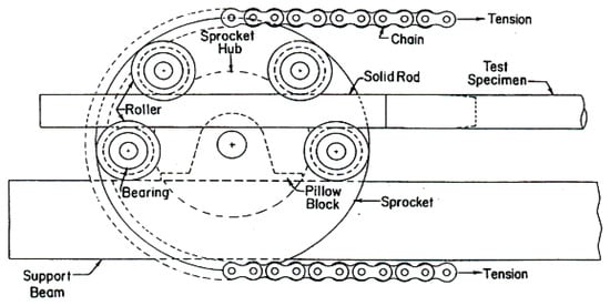
Figure 2.
Enlarged schematic diagram of the sprocket.
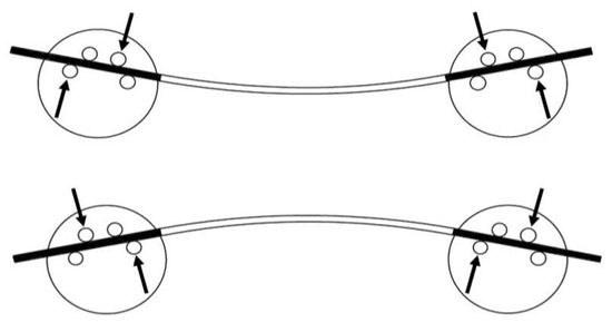
Figure 3.
Concentrated forces on rollers during both forward and reverse bending.
The spatial confines of the rollers could only accommodate solid rods with circular cross-sections, but inserting a solid rod with a circular cross-section into an elliptical tube proved infeasible. Thus, a new solid rod configuration was designed for use in the bending machine, as illustrated in Figure 4a. The disassembled configuration of the elliptical tube and newly designed solid rod is outlined in Figure 4b, and Figure 5a presents an exploded view of the newly designed solid rod. The newly designed solid rod had an elliptical cross-section on one side and circular cross-section on the other, which was achieved by welding both contact surfaces. Because the effect of changing the long–short axis ratio was being tested, solid rods with elliptical cross-sections of varying sizes had to be prepared. In contrast, the circular cross-section on the other side of the solid rods was maintained at the same size, as shown in Figure 5b.
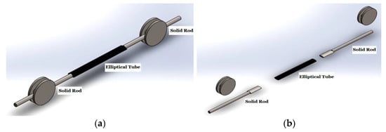
Figure 4.
(a) Schematic diagram of the newly designed solid rod erected on the tube-bending machine, and (b) disassembled diagram of the elliptical tube and the newly designed solid rod.
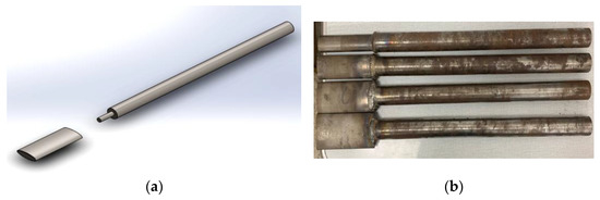
Figure 5.
(a) Schematic diagram of the exploded view of the newly designed solid rod, and (b) picture of four solid rods.
2.2. Curvature-Ovalization Measurement Apparatus (COMA)
Figure 6 shows the curvature–ovalization measurement apparatus (COMA) devised by Pan et al. [27], which is used to gauge the tube curvature and cross-sectional ovalization of tubes. Ovalization is defined as the change in outer diameter divided by the original outer diameter. This lightweight instrument was placed near the mid-span of a tube. The fixed spacing between the two side-inclinometers and the angular shifts identified by these inclinometers were used to compute the curvature of the tube. The COMA had a magnetic detector at its center to assess changes in the outer diameter of circular tubes. In this study, the COMA was employed to track variations in the short axis of elliptical tubes.
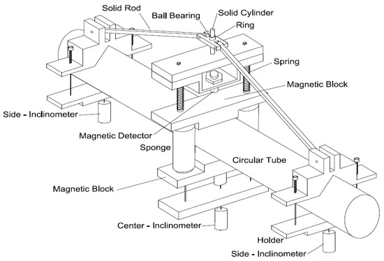
Figure 6.
Schematic diagram of the COMA.
2.3. Elliptical Tubes
SUS304 stainless steel elliptical tubes were sourced from Rongfa Stainless Steel Co., Ltd., Yilong County, Sichuan Province, China. Table 1 and Table 2 present the chemical composition and mechanical properties, respectively, of SUS304 stainless steel. The elliptical tubes had a length of 500 mm and thickness of 0.7 mm. Figure 7a shows a schematic diagram defining the long and short axes for the cross-section of an elliptical tube. As shown in Figure 7b, four different long–short axis ratios (ℓlong/ℓshort) were considered: 1.5 (30 mm/20 mm), 2.0 (40 mm/20 mm), 2.5 (50 mm/20 mm), and 3.0 (60 mm/20 mm).

Table 1.
Chemical composition of the SUS304 stainless steel (weight %).
Table 2.
Mechanical properties of the SUS304 stainless steel.
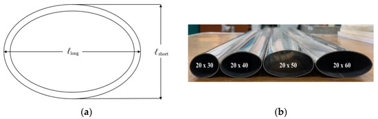
Figure 7.
(a) Schematic diagram illustrating the long axis and short axis of the cross-section of an elliptical tube, and (b) picture of SUS304 stainless steel ellipitical tubes with four different ℓlong/ℓshort ratios.
2.4. Test Procedures
Specimens were subjected to curvature-controlled cyclic bending at a curvature rate of 0.05 m−1 s−1. As shown in Figure 8, the direction of the bending moment was fixed in the x-axis direction. The orientation angle Φ was defined as the angle between the long axis and bending moment direction (i.e., x-axis direction). When the long axis was aligned with the x-axis, Φ = 0°. When the long axis was perpendicular to the x-axis, Φ = 90°. Four different Φ values were considered: 0°, 30°, 60°, and 90°. The controlled-curvature range spanned from −0.5 m−1 to +0.5 m−1 and was then further extended to −0.8 m−1 to +0.8 m−1. The bending moment (M) was determined by using load cells in the bending machine, as depicted in Figure 1. The curvature (κ) and short-axis variation (∆ℓ/ℓshort, where ∆ℓ is the change in ℓshort) were measured by using the COMA shown in Figure 6. The number of cycles required to initiate buckling (Nb) was recorded, which was defined as when the bending moment (M) decreased by 20%.
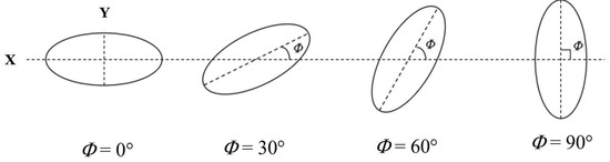
Figure 8.
Schematic diagram the cross-section of elliptical tubes at different Φ.
3. Results and Discussion
3.1. Relationship between the Moment and Curvature
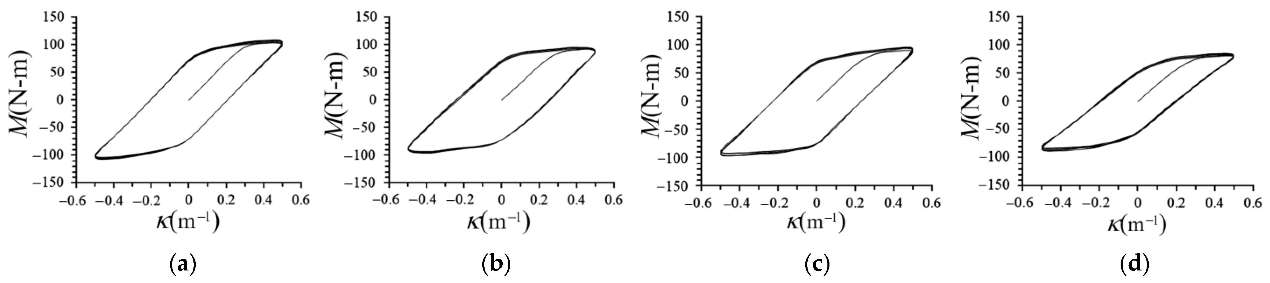
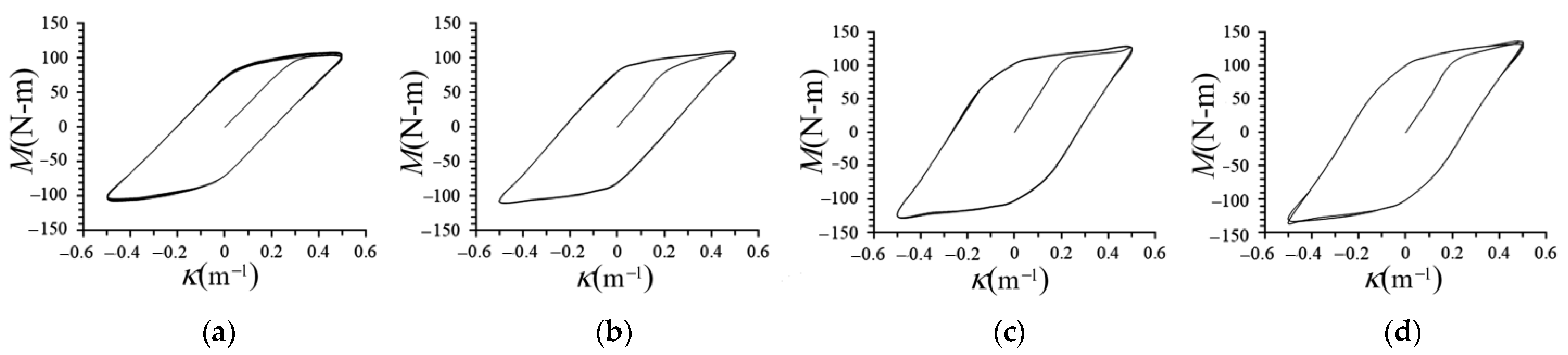
Figure 9a–d present the M–κ curves of the elliptical tubes under cycling bending with a varying ℓlong/ℓshort (1.5, 2.0, 2.5, and 3.0) and fixed Φ (0°). Figure 10a–d present the M–κ curves of the elliptical tubes under cycling bending with a fixed ℓlong/ℓshort (1.5) and varying Φ (0°, 30°, 60°, and 90°). κ was controlled within a range of +0.5 m−1 to −0.5 m−1. During the initial loading stage, the elliptical tubes were within the elastic range, which resulted in M increasing linearly with κ. As κ increased, the elliptical tube started to deform plastically, which caused the increase in M to slow and resulted in permanent deformation. All M–κ curves exhibited cyclic hardening and became stable after a few cycles. For a fixed Φ, increasing ℓlong/ℓshort caused the peak value of M to gradually decrease. For a fixed ℓlong/ℓshort, increasing Φ caused the peak value of M to gradually increase. Notably, different κ did not affect the trends of the M–κ curves. Therefore, obtaining more M–κ curves for other ℓlong/ℓshort and Φ values was judged unnecessary.

Figure 9.
Experimental M–κ relationships of SUS304 stainless steel elliptical tubes under cyclic bending with a varying ℓlong/ℓshort ((a) 1.5, (b) 2.0, (c) 2.5, and (d) 3.0) and fixed Φ (0°).
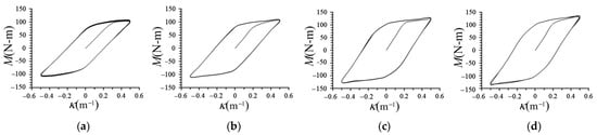
Figure 10.
M–κ curves of the elliptical tubes under cycling bending with a fixed ℓlong/ℓshort (1.5) and varying Φ ((a) 0°, (b) 30°, (c) 60°, and (d) 90°).
3.2. Relationship between the Short-Axis Variation and Curvature
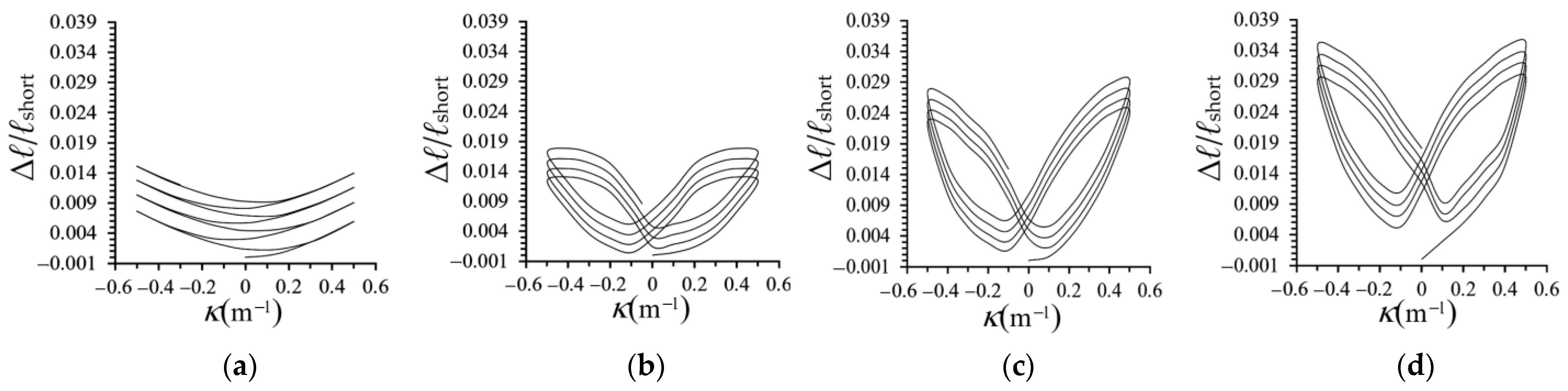
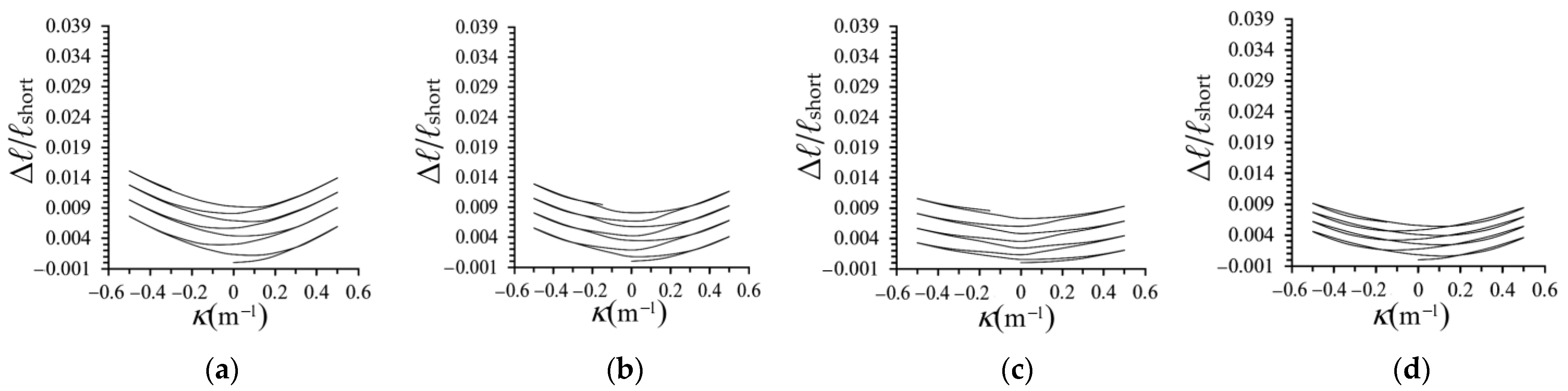
Figure 11a–d show the ∆ℓ/ℓshort–κ curves of elliptical tubes under cyclic bending with varying ℓlong/ℓshort (1.5, 2.0, 2.5, and 3.0) and fixed Φ (0°). Figure 12a–d show the ∆ℓ/ℓshort–κ relationships of elliptical tubes under cycling bending with a fixed ℓlong/ℓshort (1.5) and varying Φ (0°, 30°, 60°, and 90°). κ was confined within the range of +0.5 m−1 to −0.5 m−1. The ∆ℓ/ℓshort–κ curves exhibited a nonlinear pattern regardless of whether the elliptical tube underwent elastic or plastic bending deformation. As κ gradually increased with the load, ∆ℓ/ℓshort likewise increased gradually. When κ reached +0.5 m−1, ∆ℓ/ℓshort reached its peak value. Subsequently, ∆ℓ/ℓshort gradually decreased during unloading. However, ∆ℓ/ℓshort did not return to zero when κ reached 0 m−1, which indicated plastic deformation of the elliptical tube. As the reverse load was increased, κ and ∆ℓ/ℓshort gradually began to increase again, and ∆ℓ/ℓshort peaked when κ reached −0.5 m−1. When κ returned to 0 m−1, ∆ℓ/ℓshort increased slightly more than during the previous plastic deformation. ∆ℓ/ℓshort continued to increase with the number of cyclic bending loads. When ℓlong/ℓshort was fixed at 1.5, the ∆ℓ/ℓshort–κ curves followed a pattern marked by symmetry, ratcheting, and incremental growth as the number of cycles increased. As ℓlong/ℓshort approached a circular cross-section, the ∆ℓ/ℓshort–κ curves resembled that of a circular tube. As ℓlong/ℓshort increased, which indicated a stretching of the long axis, the cross-section tended toward an oblate configuration. Consequently, for a fixed κ, increasing ℓlong/ℓshort and Φ both increased ∆ℓ/ℓshort. When ℓlong/ℓshort ≥ 2.0, the ∆ℓ/ℓshort–κ curves showed symmetric, ratcheting, and incremental growth, and even a butterfly-like pattern. Owing to the similar trend, considering further values for ∆ℓ/ℓshort and Φ was judged unnecessary.
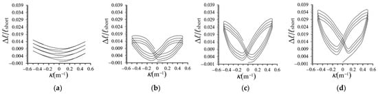
Figure 11.
Experimental Δℓ/ℓshort–κ relationships of SUS304 stainless steel elliptical tubes under cyclic bending with a varying ℓlong/ℓshort ((a) 1.5, (b) 2.0, (c) 2.5, and (d) 3.0) and fixed Φ (0°).
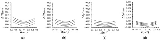
Figure 12.
Experimental Δℓ/ℓshort–κ relationships of SUS304 stainless steel elliptical tubes under cycling bending with a fixed ℓlong/ℓshort (1.5) and varying Φ ((a) 0°, (b) 30°, (c) 60°, and (d) 90°).
3.3. Relationship between the Curvature and Number of Cycles Required to Initiate Buckling
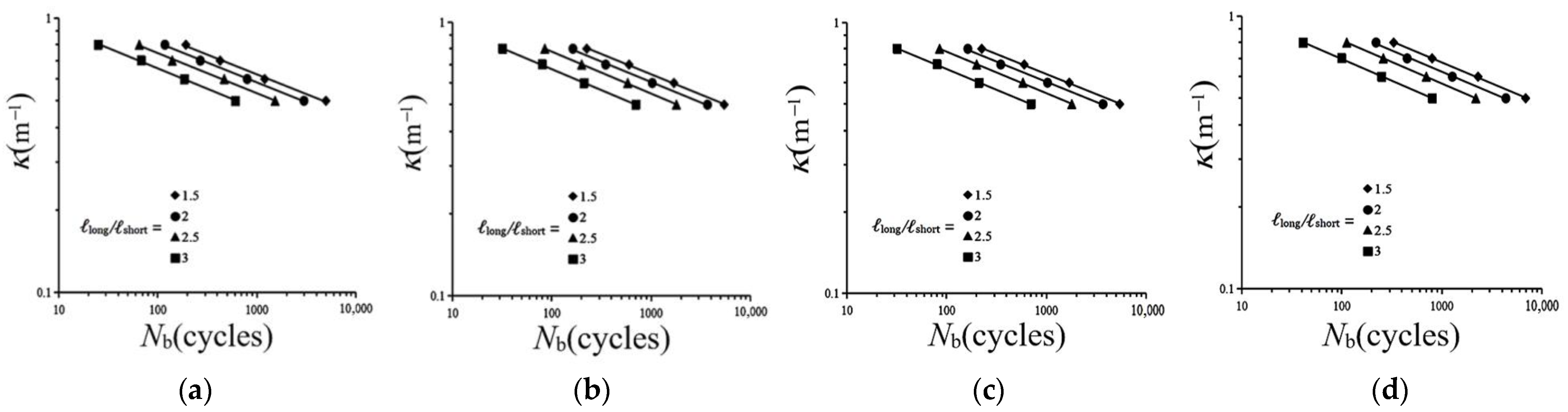
Figure 13a–d plots the κ–Nb curves of the elliptical tubes under cyclic bending with different ℓlong/ℓshort and varying Φ (0°, 30°, 60°, and 90°) on double logarithmic co-ordinates. The straight lines represent the outcome of the least-squares method. For each Φ, the four ℓlong/ℓshort correspond to four straight lines. For a fixed Φ and ℓlong/ℓshort, Nb decreased as κ increased. Similarly, for a fixed κ, Nb decreased as ℓlong/ℓshort increased. For a fixed ℓlong/ℓshort, Nb decreased as Φ increased. Note that for each κ, two elliptical tube specimens were tested, and there was no significant difference in the obtained Nb.
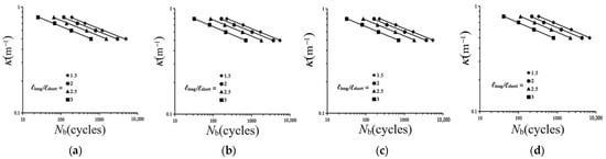
Figure 13.
Experimental κ-Nb relationships of SUS304 stainless steel elliptical tubes under cyclic bending with different ℓlong/ℓshort and varying Φ ((a) 0°, (b) 30°, (c) 60°, and (d) 90°) on double logarithmic co-ordinates.
In 1987, Kyriakides and Shaw [1] proposed the following κ/κo–Nb relationship for smooth circular tubes under cyclic bending loads:
or
where κo is used to dimensionless κ (i.e., tube thickness divided by the square of the outer diameter) while C and α are material parameters. C represents the value of κ/κo when Nb = 1, and α denotes the slope of the straight line for the κ/κo–Nb curve on double logarithmic co-ordinates. Because the current experiment employed elliptical tubes, determining κo is not possible. Consequently, Equations (1) and (2) can be respectively modified to
or
κ/κo = C(Nb)−α
logκ/κo = logC − αlogNb,
κ = C(Nb)−α
logκ = logC − αlogNb,
Based on the experimental results shown in Figure 13a–d and Figure 14a,b respectively present the logC − ℓlong/ℓshort and logα − ℓlong/ℓshort curves for different Φ. The straight lines were obtained by using the least-squares method. The four lines correspond to Φ = 0°, 30°, 60°, and 90°. Because all of the curves demonstrated linear relationships, the following empirical equations were proposed:
and
where Co, β, αo, and γ are material parameters.
logC = Co − β (ℓlong/ℓshort)
logα = αo − γ (ℓlong/ℓshort),
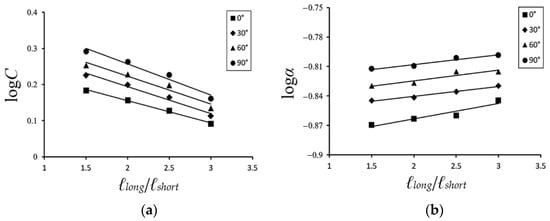
Figure 14.
(a) Relationship between logC and ℓlong/ℓshort ratio for different Φ, and (b) relationship between logα and ℓlong/ℓshort ratio for different Φ.
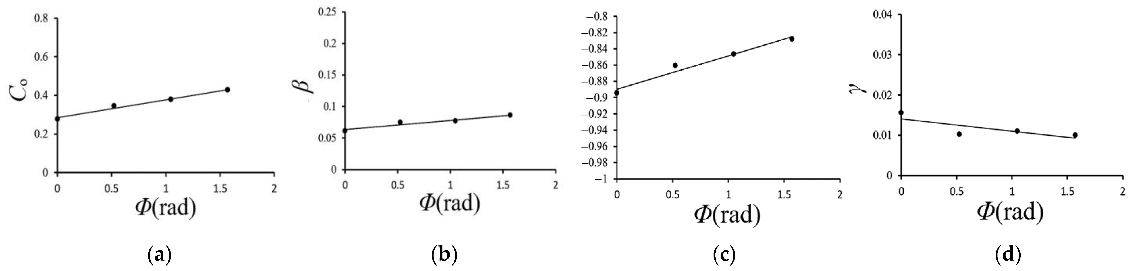
Figure 15a–d show the relationships between the material parameters Co, β, αo, γ, and Φ. Because these relationships are all linear, the following empirical equations are proposed for relating Co, β, αo, γ, and Φ:
and
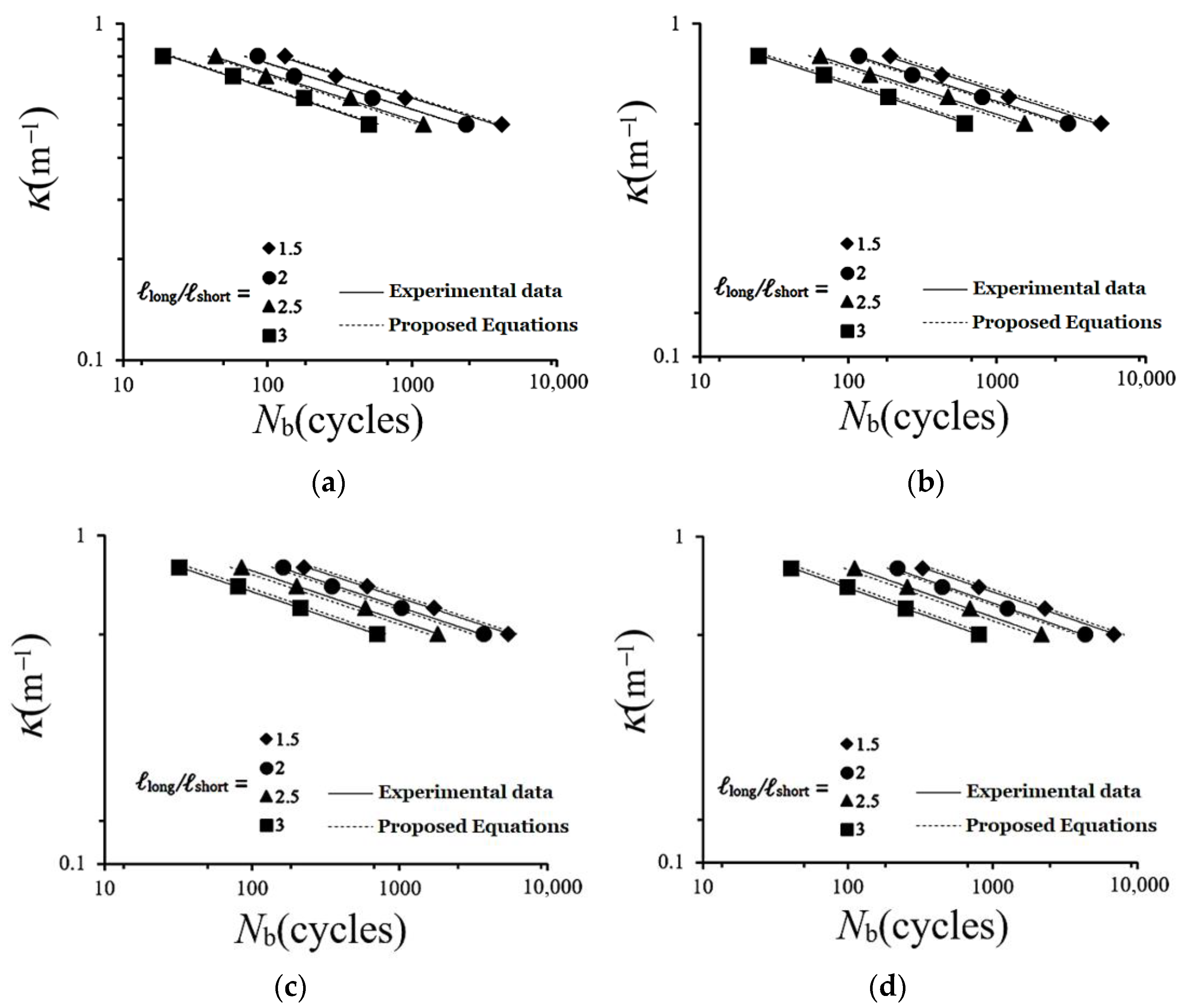
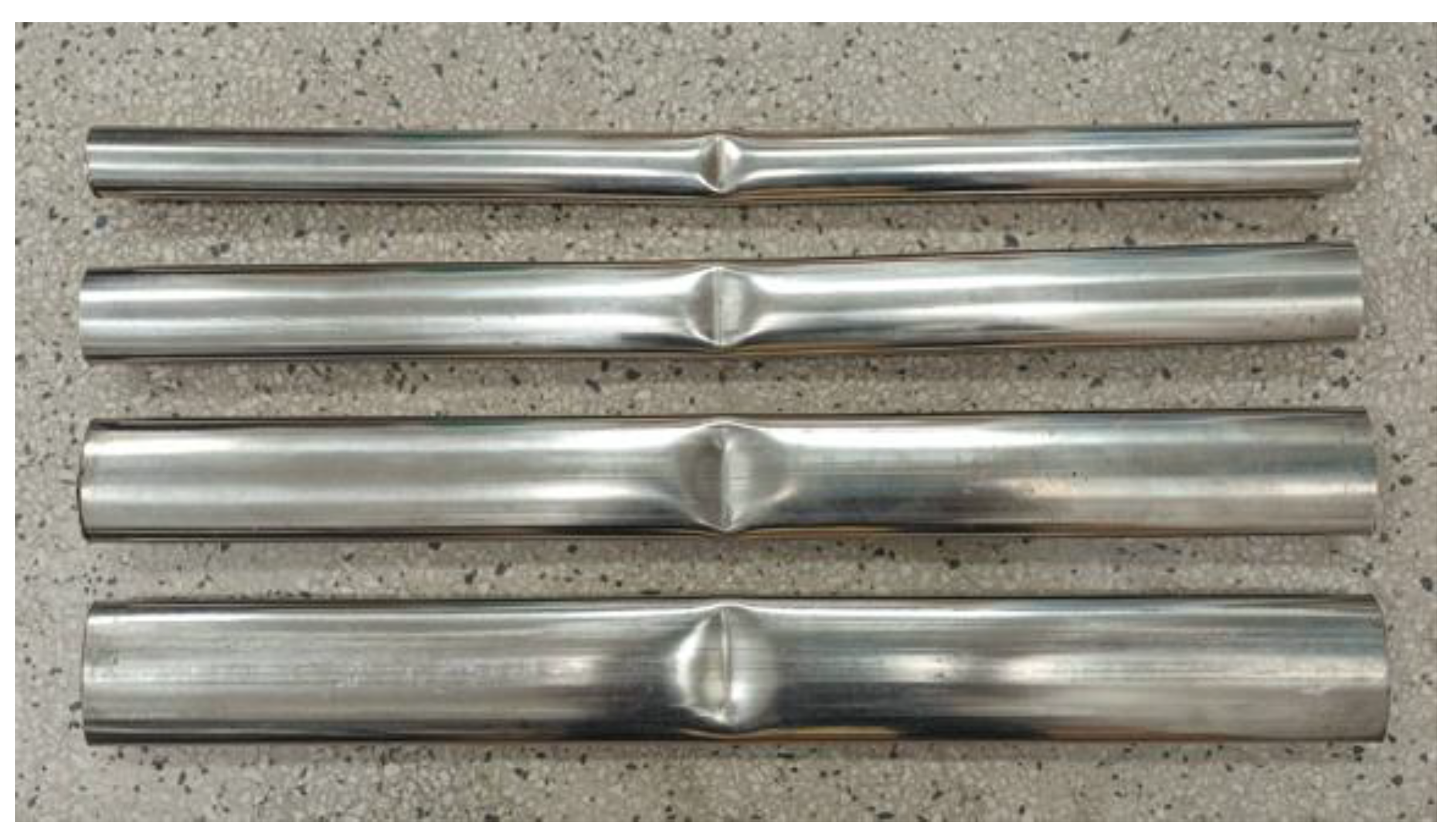
where a1, a2, b1, b2, c1, c2, d1, and d2 are material parameters. Based on the straight lines in Figure 15a–d, a1, a2, b1, b2, c1, c2, d1, and d2 were determined as 0.0929, 0.2839, 0.0146, 0.0634, 0.0942, −2.0483, −0.0071, and 0.0325, respectively. Then, Equations (4)–(10) were used to predict the κ–Nb curves of SUS304 stainless steel elliptical tubes with different ℓlong/ℓshort at Φ = 0°, 30°, 60°, 90°. The predicted outcomes are depicted in Figure 16a–d as dashed lines. Comparison with the experimental results showed that the proposed equations adequately and reasonably described the experimental findings. In addition, Figure 17 displays a photograph depicting buckling in elliptical tubes, and it specifically showcases instances with four different ℓlong/ℓshort ratios.
Co = a1Φ + a2
β = b1Φ + b2
αo = c1Φ + c2
γ = d1Φ + d2,

Figure 15.
(a) Relationship between Co and Φ, (b) relationship between β and Φ, (c) relationship between αo and Φ, and (d) relationship between γ and Φ.
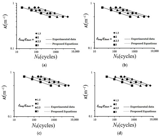
Figure 16.
Experimental and descriptive κ–Nb relationships of SUS304 stainless steel elliptical tubes under cyclic bending with different ℓlong/ℓshort and varying Φ ((a) 0°, (b) 30°, (c) 60°, and (d) 90°) on double logarithmic co-ordinates.
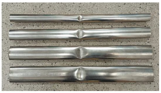
Figure 17.
Photograph depicting buckling in elliptical tubes.
4. Conclusions
This study investigated the behavior and failure mechanisms of SUS304 stainless steel elliptical tubes under cyclic bending with different ℓlong/ℓshort (1.5, 2.0, 2.5, and 3.0) and Φ (0°, 30°, 60°, and 90°). Only curvature-controlled symmetric pure bending loads were considered, which means that the forward and reverse κ were equal quantities. Based on the results, several key conclusions were drawn:
- (1)
- During the initial loading stage, the elliptical tubes were in the elastic range, so M increased linearly with increasing κ. As κ increased further, the elliptical tubes started to deform plastically, which caused a gradual flattening of the M–κ curves and resulted in permanent deformation. All M–κ curves exhibited cyclic hardening and became stable after a few cycles. For a fixed Φ, increasing ℓlong/ℓshort gradually decreased the peak M value. For a fixed ℓlong/ℓshort, increasing Φ gradually increased the peak M value.
- (2)
- The ∆ℓ/ℓshort–κ curves exhibited a nonlinear pattern regardless of whether the elliptical tube was subjected to elastic or plastic bending deformation. As the number of cyclic bending loads increased, ∆ℓ/ℓshort continued to increase. For a fixed Φ and ℓlong/ℓshort of 1.5, the ∆ℓ/ℓshort–κ curves showed symmetry, serrations, and a growth pattern as the number of cycles increased. This similarity to the behavior of circular tubes can be attributed to ℓlong/ℓshort being close to that of a circular cross-section. When ℓlong/ℓshort exceeded 2.0, the ∆ℓ/ℓshort–κ curves displayed a symmetric, serrated, growing, and even butterfly-like pattern. A larger ℓlong/ℓshort corresponded to a larger ∆ℓ/ℓshort. For a fixed ℓlong/ℓshort, increasing Φ decreased ∆ℓ/ℓshort.
- (3)
- For a fixed Φ and ℓlong/ℓshort, Nb decreased with increasing κ. For a fixed κ, Nb decreased with increasing ℓlong/ℓshort. For a fixed ℓlong/ℓshort, Nb decreased with increasing Φ. When these relationships were plotted on double logarithmic co-ordinates, it became apparent that the four distinct ℓlong/ℓshort corresponded to four straight lines for each Φ. Moreover, the four straight lines had distinct slopes and intercepts.
- (4)
- Equation (3) or (4) can be used to describe the κ2013Nb curves. The experimental data were utilized to identify linear logC − ℓlong/ℓshort relationships (Figure 14a) and logα − ℓlong/ℓshort relationships (Figure 14b), which allowed Equations (5) and (6) to be derived. The data in Figure 14a,b were used to establish a linear Co − Φ relationship (Figure 15a), β − Φ relationship (Figure 15b), αo − Φ relationship (Figure 15c), and γ − Φ relationship (Figure 15d), which allowed Equations (7)–(10) to be derived. Equations (4)–(10) were then employed to describe the κ–Nb relationships for SUS304 stainless steel elliptical tubes under cyclic bending with different ℓlong/ℓshort and different Φ. They showed good agreement with the experimental data, as shown in Figure 16a–d. This indicates that the proposed equations reasonably describe the experimental results.
Author Contributions
Conceptualization, W.-F.P. and M.-C.Y.; methodology, W.-F.P.; software, M.-C.Y.; validation, W.-F.P. and M.-C.Y.; formal analysis, W.-F.P. and M.-C.Y.; investigation, M.-C.Y.; resources, W.-F.P.; data curation, M.-C.Y.; writing—original draft preparation, W.-F.P.; writing—review and editing. All authors have read and agreed to the published version of the manuscript.
Funding
This research was supported by the National Science and Technology Council Funds (NSTC 112–2221–E–006–174).
Data Availability Statement
Data are contained within the article.
Acknowledgments
The research was conducted with the generous support of the National Science and Technology Council. We extend our heartfelt gratitude for their invaluable assistance.
Conflicts of Interest
The authors declare no conflict of interest.
References
- Kyriakides, S.; Shaw, P.K. Inelastic buckling of tubes under cyclic bending. J. Pres. Ves. Technol. 1987, 109, 169–178. [Google Scholar] [CrossRef]
- Corona, E.; Kyriakides, S. An experimental investigation of the degradation and buckling of circular tubes under cyclic bending and external pressure. Thin-Walled Struct. 1991, 12, 229–263. [Google Scholar] [CrossRef]
- Corona, E.; Kyriakides, S. Asymmetric collapse modes of pipes under combined bending and pressure. Int. J. Solids Struct. 2000, 24, 505–535. [Google Scholar] [CrossRef]
- Corona, E.; Lee, L.H.; Kyriakides, S. Yield anisotropic effects on buckling of circular tubes under bending. Int. J. Solids Struct. 2006, 43, 7099–7118. [Google Scholar] [CrossRef]
- Limam, A.; Lee, L.H.; Corana, E. Inelastic wrinkling and collapse of tubes under combined bending and internal pressure. Int. J. Mech. Sci. 2010, 52, 37–47. [Google Scholar] [CrossRef]
- Limam, A.; Lee, L.H.; Corona, E.; Kyriakides, S. On the collapse of dented tubes under combined bending and internal pressure. Int. J. Solids Struct. 2012, 55, 1–12. [Google Scholar] [CrossRef]
- Bechle, N.J.; Kyriakides, S. Localization of NiTi tubes under bending. Int. J. Solids Struct. 2014, 51, 967–980. [Google Scholar] [CrossRef]
- Jiang, D.; Kyriakides, S.; Bechle, N.J.; Landis, C.M. Bending of pseudoelastic NiTi tubes. Int. J. Solids Struct. 2017, 124, 192–214. [Google Scholar] [CrossRef]
- Kazinakis, K.; Kyriakides, S.; Jiang, D.; Bechle, N.J.; Landis, C.M. Buckling and collapse of pseudoelastic NiTi tubes under bending. Int. J. Solids Struct. 2021, 221, 2–17. [Google Scholar] [CrossRef]
- Yuan, W.; Mirmiran, A. Buckling analysis of concrete-filled FRP tubes. Int. J. Struct. Stab. Dyn. 2001, 1, 367–383. [Google Scholar] [CrossRef]
- Elchalakani, M.; Zhao, X.L.; Grzebieta, R.H. Plastic mechanism analysis of circular tubes under pure bending. Int. J. Mech. Sci. 2002, 44, 1117–1143. [Google Scholar] [CrossRef]
- Houliara, S.; Karamanos, S.A. Buckling and post-buckling of long pressurized elastic thin-walled tubes under in-plane bending. Int. J. Nonlinear Mech. 2006, 44, 491–511. [Google Scholar] [CrossRef]
- Elchalakani, M.; Zhao, X.L.; Grzebieta, R.H. Variable amplitude cyclic pure bending tests to determine fully ductile section slenderness limits for cold-formed CHS. Eng. Struct. 2006, 28, 1223–1235. [Google Scholar] [CrossRef]
- Zhi, X.D.; Fan, F.; Shen, S.Z. Failure mechanism of single-layer cylindrical reticulated shells under earthquake motion. Int. J. Struct. Stab. Dyn. 2012, 12, 233–249. [Google Scholar] [CrossRef]
- Yazdani, H.; Nayebi, A. Continuum damage mechanics analysis of thin-walled tube under cyclic bending and internal constant pressure. Int. J. Appl. Mech. 2013, 5, 1350038. [Google Scholar] [CrossRef]
- Guo, L.; Yang, S.; Jiao, H. Behavior of thin-walled circular hollow section tubes subjected to bending. Thin-Walled Struct. 2013, 73, 281–289. [Google Scholar] [CrossRef]
- Shariati, M.; Kolasangiani, K.; Norouzi, G.; Shahnavaz, A. Experimental study of SS316L cantilevered cylindrical shells under cyclic bending load. Thin-Walled Struct. 2014, 82, 124–131. [Google Scholar] [CrossRef]
- Elchalakani, M.; Karrech, A.; Hassanein, M.F.; Yang, B. Plastic and yield slenderness limits for circular concrete filled tubes subjected to static pure bending. Thin-Walled Struct. 2016, 109, 50–64. [Google Scholar] [CrossRef]
- Shamass, R.; Alfano, G.; Guarracino, F. On elastoplastic buckling analysis of cylinders under nonproportional loading by differential quadrature method. Int. J. Struct. Stab. Dyn. 2017, 17, 1750072. [Google Scholar] [CrossRef]
- Li, P.; Wang, L. Nonlinear stability behavior of cable-stiffened single-layer latticed shells under earthquakes. Int. J. Struct. Stab. Dyn. 2018, 18, 1850117. [Google Scholar] [CrossRef]
- Chegeni, B.; Jayasuriya, S.; Das, S. Effect of corrosion on thin-walled pipes under combined internal pressure and bending. Thin-Walled Struct. 2019, 143, 106218. [Google Scholar] [CrossRef]
- Jin, S.; Cheng, P.; Saneian, M.; Yong, B. Mechanical behavior of thin tubes under combined axial compression and bending. Thin-Walled Struct. 2021, 159, 107255. [Google Scholar] [CrossRef]
- Da Silveira, T.; Pinto, V.T.; Neufeld, J.P.; Pavlovic, A.; Rocha, L.A.; Dos Santos, E.D.; Isoldi, L.A. Applicability evidence of constructal design in structural engineering: Case study of biaxial elasto-plastic buckling of square steel plates with elliptical cutout. J. Appl. Comput. Mech. 2021, 7, 922–934. [Google Scholar]
- He, Z.R.; Li, G.J.; Yang, J.C.; Guo, X.Z.; Duan, X.Y.; Guo, W.; Liu, X.; Deng, Y.Y.; Cheng, C. Insight into the deformation transition effect in free bending of tubes. Thin-Walled Struct. 2023, 348, 134673. [Google Scholar] [CrossRef]
- Wang, J.; Li, J.R.; Li, H.; Lv, L.Y. Behaviour of square concrete-filled steel tubes reinforced with internal latticed steel angles under bending. Structures 2023, 48, 1436–1454. [Google Scholar] [CrossRef]
- Lee, K.L.; Tsai, Y.C.; Pan, W.F. Mean curvature effect on the response and failure of round-hole tubes submitted to cyclic bending. Adv. Mech. Eng. 2021, 13, 1–14. [Google Scholar] [CrossRef]
- Pan, W.F.; Wang, T.R.; Hsu, C.M. A curvature-ovalization measurement apparatus for circular tubes under cyclic bending. Exp. Mech. 1998, 38, 99–102. [Google Scholar] [CrossRef]


Disclaimer/Publisher’s Note: The statements, opinions and data contained in all publications are solely those of the individual author(s) and contributor(s) and not of MDPI and/or the editor(s). MDPI and/or the editor(s) disclaim responsibility for any injury to people or property resulting from any ideas, methods, instructions or products referred to in the content. |
© 2023 by the authors. Licensee MDPI, Basel, Switzerland. This article is an open access article distributed under the terms and conditions of the Creative Commons Attribution (CC BY) license (https://creativecommons.org/licenses/by/4.0/).