Abstract
This paper conducts a comprehensive analysis of the varying thickness rolling process, grounded in the principle of pre-displacement. Within the rolling deformation zone, the subject is divided into three distinct areas: the backward slip zone, sticking zone, and forward slip zone. We propose a model that delineates the sticking-sliding motion between the rolled piece and the roller, all within the context of the rolling deformation zone, and derive a calculation method for determining the longitudinal lengths of both the sliding and sticking zones within this area. Unlike existing full sliding and full sticking models, our sticking-sliding model offers a novel perspective, overcoming inherent limitations when analyzing the rolling process. Furthermore, we establish models to describe the neutral angle and forward slip value and to predict the longitudinal length of the rolled piece during the varying thickness rolling process. A comparison of our calculated results with experimental data demonstrates the feasibility and effectiveness of the method, thereby laying a robust theoretical foundation for the varying thickness rolling process.
1. Introduction
Rolling is a metal working process in which metal billets are passed through the gap of a pair of rotating rolls, and the section of the material is reduced and the length is increased due to the compression of the rolls. Rolling represents one of the predominant processes in metalworking. Coinciding with technological advances and the evolution of rolling equipment, the varying thickness rolling process, characterized by the continuous modification of roll gap size, has come to fruition. This innovation furnishes technological assurance for objectives such as minimizing production loss, augmenting efficiency, and diversifying rolling products [1,2].
For instance, in the fabrication of medium and thick plates, plane shape control technology is employed in order to reduce the loss of the steel plate rolling process and improve the economic benefit. Since the 1980s, relevant companies began to develop planar shape control rolling technology. This technology is based on the metal rolling deformation law through the control of the section shape of the plate; the final plane shape of the product tends to be rectangular to achieve the purpose of reducing the cutting rate [3]. The core process of plane shape control technology necessitates the use of the varying thickness rolling technique in the intermediate rolling pass to create a longitudinal thickness difference structure. In turning over steel, the transverse thickness discrepancy in the sheet can offset the non-uniform edge shape during rolling, thereby directing its planar form toward a rectangular shape and accomplishing a reduction in the amount of cutting [4,5].
Another illustration pertains to longitudinally profiled steel plates (LP steel plates) and tailor rolling blanks (TRBs) [6]. There are two traditional processes for the production of variable thickness plates, using steel plates of different thicknesses for welding, or using mechanical milling processes to process thick plates. These two kinds of processes have the disadvantages of poor mechanical properties at the welding and large processing losses. LP steel plates and TRBs can perfectly result in these drawbacks, wherein material savings and weight reduction are attainable without compromising mechanical performance. The principal process in their production likewise revolves around varying thickness rolling [7,8].
In contrast to conventional rolling, the variable thickness rolling process can continuously adjust the size of the roll gap during rolling, resulting in the production of a rolling tilt angle. The variable thickness rolling introduces alterations in parameters such as rolling force, bite conditions, contact arc length between the rolled piece and the roller, and rolling exit position, attributable to the rolling tilt angle. These variations signify that extant conventional rolling theoretical models are inadequate for precisely depicting the varying thickness rolling process [9,10]. To construct a meticulous and encompassing theoretical model of varying thickness rolling, the relative motion between the rolled piece and the roller must initially be modeled, constituting the foundational analysis for the rolling process [11,12].
Currently, the relative motion models during the varying thickness rolling process predominantly bifurcate into two categories: the full sliding model and the full sticking model [13].
In the rolling process, the phenomenon that the outlet speed of the rolled metal is greater than the circumference speed of the roll is called the forward slip phenomenon, and the described parameter is called the front slip value. The area where the forward slip phenomenon occurs is the forward slip zone. The phenomenon that the inlet speed of the rolled metal is less than the circular speed of the roll is called the backward slip phenomenon, and the area where the backward slip phenomenon occurs is the backward slip zone. The critical plane of the forward slip zone and the backward slip zone is the neutral plane, and the corresponding angle is the neutral angle. The foundational assumption of the full sliding model is that a perpetual relative sliding state exists between the rolled piece and the roller, segmenting the rolling deformation zone into two regions: the forward slip zone and the backward slip zone, as delineated in Figure 1. In Figure 1, is the rolling neutral angle and is the rolling tilt angle.
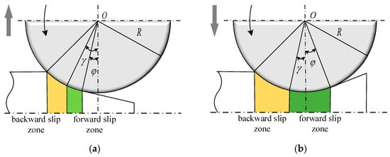
Figure 1.
Schematic diagram of varying thickness rolling with full sliding model: (a) schematic diagram of thickening rolling; (b) schematic diagram of thinning rolling.
Conversely, the full sticking model posits that the rolled piece and the roller remain relatively immobile; there is no forward slip and no backward slip. Given the continuous fluctuation in exit thickness in varying thickness rolling, the full sticking model necessitates that the rolled piece be discretized when analyzing the process, longitudinally dividing it into multiple fully sticking zones, with computations for rolling process parameters executed independently for each segment [14].
A plethora of experimental evidence demonstrates that the actual relative motion within the rolling deformation zone is neither entirely sliding nor fully adhered. A sticking zone materializes between the forward slip zone and the backward slip zone where the rolled piece and the roller are relatively stationary.
It is well known that the motion model of rolled piece and roll is the basic premise for the analysis and on-line control of processes with variable thickness rolling. The purpose of this paper is to develop a new mathematical model, called the “sticking-sliding” model, which can represent the relative motion of rolled piece and roller by combining the existing full-sliding hypothesis with the full-sticking hypothesis. The sticking-sliding model can represent the relative motion between rolled piece and roller more accurately than the existing model, and it can effectively improve the calculation accuracy of the relative motion parameters between rolled piece and roller. This research can provide theoretical support for process analysis and on-line control of variable thickness rolling [15].
2. Characteristics of Longitudinal Varying Thickness Rolling
In the conventional rolling process, the roll gap remains unchanged, which is a stable system, so the motion parameters between the rolled piece and the roller are constant. Varying thickness rolling constitutes a process that facilitates the continuous alteration in the thickness of the exit cross-section of the rolled piece, in line with specific technological mandates [16]. Predicated on the progression of roll gap modifications, longitudinal varying thickness rolling may be bifurcated into two main types: thinning rolling and thickening rolling [17,18]. In the rolling process, the roll gap is gradually reduced, which is called thinning rolling, and the roll gap is gradually increased, which is called thickening rolling.
Compared with conventional rolling, variable thickness rolling is obviously an unstable rolling process [19,20]. In this process, with the continuous change in the thickness of the rolled piece, the motion parameters between the rolled piece and the roller also change [21,22].
Examining the geometric relationship between the rolled piece and the roller. within the thickening rolling procedure, the roll gap experiences a gradual enlargement, leading to a rearward shift in the exit point position compared to conventional rolling [23]. Concurrently, the contact arc length between the rolled piece and the roller contracts, and the rolling deformation zone recedes [24]. The thinning rolling process observes a gradual constriction in the roll gap, resulting in a forward shift in the exit point position relative to conventional rolling, along with an expansion of the contact arc length between the rolled piece and the roller, and an enlargement of the rolling deformation zone [25]. The process characteristics of variable thickness rolling are shown in Table 1.

Table 1.
Comparative table of process characteristics of varying thickness rolling.
Throughout the varying thickness rolling process, the geometric relationship and force conditions at the bite moment between the rolled piece and the roller remain consistent with conventional rolling. This consistency imparts an understanding that the bite conditions for varying thickness rolling are commensurate with those for conventional rolling [26].
Compared to conventional rolling, in the stable varying thickness rolling process, the continuous change in roll gap generates a rolling tilt angle, causing changes in the resultant angle of the rolling force applied to the rolled piece. Consequently, the horizontal components of the resultant rolling force and the frictional force also change [27]. As shown in Figure 2, represents the bite angle, represents the rolling tilt angle, represents the resultant angle of the rolling force, represents the resultant rolling force, represents the horizontal component of the resultant rolling force, represents the frictional force, and represents the horizontal component of the frictional force.
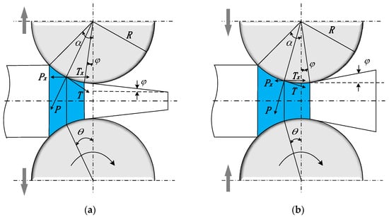
Figure 2.
Schematic diagram of varying thickness rolling: (a) schematic diagram of thickening rolling; (b) schematic diagram of thinning rolling.
Force analysis of the stable varying thickness rolling process reveals that, compared to conventional rolling, the stable thickening rolling process is more easily realized, while the stable thinning rolling process is more challenging to implement. The stable variable thickness rolling conditions and correlation coefficients are shown in Table 2.
Table 2.
Comparative table of varying thickness rolling conditions and parameters.
3. Sticking-Sliding Model Based on the Principle of Pre-Displacement
3.1. The Pre-Displacement Principle and the Three-Zone Division in the Rolling Deformation Area
From conventional understanding, it is recognized that in order to induce relative motion between two objects pressed against each other, a force acting tangentially to the contact area must be exerted upon the system. Until this sliding force attains a particular critical threshold, the objects remain macroscopically stationary. Once this sliding force surpasses the critical value, relative motion between the objects is initiated. During the phase when the objects are macroscopically static, certain microscopic relative displacements transpire, termed pre-displacement or initial displacement. The corresponding pre-displacement at the critical threshold of the sliding force is designated as the limit pre-displacement [28].
The force interplay between the rolled piece and the roller within the rolling deformation area aligns with the force system delineated by the pre-displacement principle. From this foundation, it can be inferred that when the relative displacement between the rolled piece and the roller exceeds the limit pre-displacement, macroscopic relative motion is manifested, forming the sliding zone. Conversely, when the relative displacement falls below the limit pre-displacement, the objects remain macroscopically static, constituting the sticking zone. In the sticking zone, the rolled piece and the roller are relatively static in macro.
As show in Figure 3, is the rolling neutral surface, and are the critical surfaces of the sticking zone and the sliding zone, and is the longitudinal length of the rolling deformation zone.
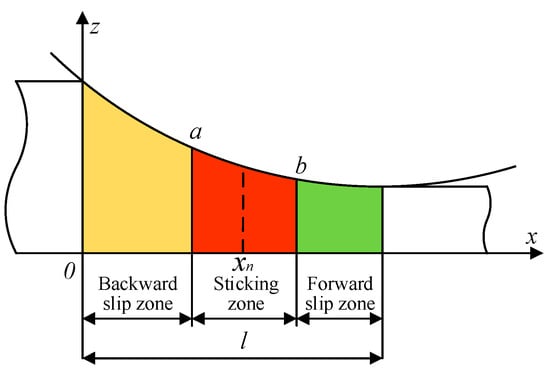
Figure 3.
Schematic diagram of three sections of rolling deformation zone.
The value of rolling neutral surface can be determined according to the calculation principle of neutral angle and represented as [11]:
where is the radius of the roller, is the length from the center of the roller to the rolling neutral surface (when the elastic change of the roll is not considered, ), and is the friction coefficient.
Upon the metal making contact with the roller and successfully engaging the roll gap, the horizontal velocity typically falls short of the horizontal constituent of the roll line speed, leading to a backward sliding phenomenon; this region is demarcated as the backward sliding zone. As the metal advances toward the central part of the roll gap, the backward sliding value incrementally diminishes. When the relative displacement between the rolled piece and the roller falls below the limit pre-displacement, the two become macroscopically static, entering the sticking zone. As the metal continues its flow towards the rolling exit direction, the pre-displacement gradually contracts until it is nullified at the neutral plane; as the metal persists in its flow towards the exit, the rolled piece and the roll generate pre-displacement anew. Upon breaching the limit pre-displacement, they once again engage in macroscopic relative displacement. At this juncture, the horizontal velocity of the rolled piece surpasses the horizontal component of the roll line speed, culminating in a forward sliding phenomenon, and the metal transitions into the forward sliding zone, continuing until the rolling exit. Consequently, the tripartite division of the rolling deformation area is formulated utilizing the pre-displacement principle. The sticking-sliding model, which encompasses both the sliding and adhesive zones, furnishes a more accurate characterization of the relative displacement between the rolled piece and the roll, thereby amplifying the computational accuracy of the rolling performance parameters [29,30].
3.2. Calculation of Limit Pre-Displacement and Longitudinal Length of the Sticking Zone
To facilitate calculation, the contact between the roller and the rolled piece in the rolling process is viewed as the process of a rigid micro-convex body squeezing a rigid-plastic body [31]. The plastic contact limit pre-displacement can be represented as
where is ultimate preparatory displacement, and is diameter of the contact spot on the roller surface.
According to the principles of friction wear calculation, the formula for calculating the diameter of the contact spot under plastic contact conditions is known to be
where is comprehensive parameters of contact surfaces, is the microscopic convex body shape factor of roll surface, is rolling pressure per unit area, is yield limit of rolled piece, is power approximate parameter of contact surface curve, and is curvature radius of the micro-convex body.
The composite parameters involved in Equation (3), influenced by the roughness of the roll surface, are related to the power approximation parameter of the contact surface curve, the maximum height of the micro-profile, contact surface curve parameters, and micro-convex body curvature radius, among others, and can be represented as
where is the maximum height of the micro-profile, and is parameters of the contact surface curve.
Since the values of various parameters in Equation (4) are affected by the roughness grade, the values of the micro-convex body parameters involved in the calculation of the contact spot diameter are also related to the roughness of the roll surface. The micro-convex body parameters corresponding to common roughness grades on the roll surface are shown in Table 3.
Table 3.
Comparative table of common roughness grades and related parameters.
As shown in Figure 4, the two surfaces a and b located on both sides of the neutral surface are taken as the critical surfaces between the sliding zone and the sticking zone. According to the above analysis, it can be determined that the relative displacement between the rolling element and the roller on the critical surface is equal to the ultimate pre-displacement.
where is the relative displacement between the rolled piece and the roller at critical surface a, is the relative displacement between the rolled piece and the roller at critical surface b, and is the length of the sticking zone.
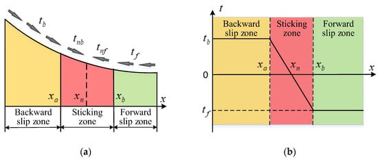
Figure 4.
The friction force of the contact surface and the trend of friction change. (a) Schematic diagram of the friction force of the contact surface; (b) trend diagram of the friction force.
Based on the geometric relationship between the rolled piece and the roll in the deformation zone, the values of point and point can be determined, and the expression is
According to Equations (5) and (6), the length of the adhesive region can be obtained; the expression is
3.3. Variation Pattern of the Friction Force on the Contact Surface
The friction force between the rolled piece and the roller is a crucial rolling parameter, and a reasonable friction model plays a vitally important role in analyzing the rolling process and accurately calculating the rolling parameters [32]. According to the pre-displacement principle, the sliding zones and the sticking zones exist between the rolled piece and the roller. Based on this, the friction force on the contact surface within the deformation zone is analyzed, and the trend of friction force change is obtained [33]. This is shown in Figure 4.
To facilitate calculation, the rolling force on the contact surface is regarded as a uniform distribution. The friction force per unit area of the forword slip zone and the backward slip zone are equal in magnitude and opposite in direction, and the expression is
where is the friction per unit area of the backward slip zone, is the friction per unit area of the forward slip zone, and is the coefficient of friction.
Within the sticking zone, the rolled piece and the roller remain relatively stationary, but friction force still exists. As the metal moves from the backward sliding zone into the sticking zone, the friction force gradually decreases, reaching zero at the neutral plane. As the metal continues to flow toward the exit direction, the friction force gradually increases, but the direction is opposite to before. According to the pre-displacement principle, the expression for the friction force in the sticking zone is
where is the friction force per unit area between the backward slip zone and the neutral surface, and is the friction force per unit area between the forward slip zone and the neutral surface.
4. Variable Thickness Rolling Based on the Sticking-Sliding Model
4.1. Calculation of Neutral Angles Based on the Sticking-Sliding Model
Building on the idea of dividing the rolling deformation zone into three sections, concepts of the front neutral angle and the back neutral angle are introduced based on the existing neutral angle . The angle corresponding to the critical point between the sticking zone and the forward slip zone is the front neutral angle, and the angle corresponding to the critical point between the sticking zone and the backward slip zone is the back neutral angle. The region between the front and back neutral angles is the sticking zone. This is shown in Figure 5. The region shown by AB is the backward slip zone, the region shown by BC is the sticking zone, and the region shown by CD is the forward slip zone.
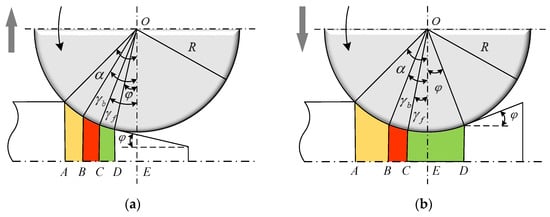
Figure 5.
The schematic diagram of three zones of rolling deformation: (a) schematic diagram of thickening rolling; (b) schematic diagram of thinning rolling.
Viewing the entire rolling deformation zone as an overall force system, the metal in the roll gap is mainly affected by the forward and backward tensile forces on the sheet, the rolling force, and the friction force between the roll and metal. In a stable rolling process, the horizontal forces on the rolled piece must be balanced. Considering the force situation in various zones, the following force balance equation can be obtained:
where is the horizontal resultant force of the forward and backward tensile force, is the resultant force in the horizontal direction in the forward slip zone, is the resultant force in the horizontal direction in the sticking slip zone, and is the resultant force in the horizontal direction in the backward slip zone.
When the forward tension and backward tension are not applied in the rolling process or the forward tension and backward tension are equal, . The Equation (10) can be expressed as follows:
Firstly, the thickening rolling as shown in Figure 6a is taken as the research object, and the stress analyses of the forward slip zone, sticking zone, and backward slip zone are carried out, respectively.
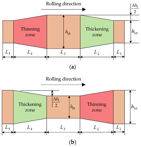
Figure 6.
The schematic diagram of the target structure of the specimens: (a) schematic diagram of the target structure of specimens 1~4; (b) schematic diagram of the target structure of specimens 5~8.
Within the forward slip zone, the metal slides forward relative to the roller in the horizontal direction, and the directions of the horizontal components of the rolling force and the friction force are the same. Based on this, the horizontal force expression in the forward slip zone is
where is the friction per unit area of the forward slip zone.
Within the sticking zone, the metal is relatively stationary to the roller in the horizontal direction. As shown in Figure 5a, the sticking zone is divided into two parts using the neutral angle as a boundary, and the directions of the horizontal components of the friction force on the contact surfaces of these two parts are opposite. The force expression is
where is the friction per unit area of the sticking zone.
Within the backward slip zone, the metal slides backward relative to the roller in the horizontal direction, and the directions of the horizontal components of the rolling force and the friction force are in opposite directions. Based on this, the horizontal force expression in the backward slip zone is
where is the friction per unit area of the backward slip zone.
To simplify the calculation process, the rolling force per unit area p is considered to be uniformly distributed along the contact surface, and the friction forces on the front and back contact surfaces of the sticking zone are equal in magnitude and opposite in direction. Based on this, due to the overall balance of the force system, substituting Equations (12)–(14) into Equation (11), the force balance equation for the deformation zone in the thickening rolling process can be obtained:
Based on the principle of pre-displacement, the relationship between the length of the sticking zone and the front and back neutral angles can be expressed as follows:
The friction force of the rolling piece is simplified, and the friction force in the forward slip zone and the backward slip zone are regarded as uniform distributions. By solving Equations (8), (15), and (16) simultaneously, the expressions of front neutral angle and back neutral angle in thickening rolling can be obtained as follows:
When the research object is thinning rolling as shown in Figure 6b, based on the above calculation ideas of the front neutral angle and back neutral angle of thickening rolling, the expressions of front neutral angle and back neutral angle of the thinning rolling process can be determined as follows:
According to Formula (7), the longitudinal length of the sticking zone can be calculated, and the values of the forward neutral angle and back neutral angle can be obtained by bringing it into Formulas (17) and (18).
4.2. Calculation of Longitudinal Length of the Deformation Zone Based on the Sticking-Sliding Model
Due to the existence of the sticking zone, the calculation of the longitudinal lengths of the forward and backward slip zones is different from the calculation of the forward and backward slip zones’ longitudinal lengths in the full sliding model.
Considering the thickening rolling shown in Figure 6a as the object of study, it is known that the forward slip zone’s longitudinal length is line segment CD, and the backward slip zone’s longitudinal length is line segment AB. By solving for the geometric lengths of the various line segments in the figure, the expressions for the forward slip zone’s longitudinal length and the backward slip zone’s longitudinal length during the thickening rolling process can be obtained:
Based on Equation (19), the thinning rolling shown in Figure 6b is analyzed. Based on geometric relationships, it is known that the calculation of the backward slip zone’s longitudinal length in the thinning rolling process is consistent with the calculation process of the backward slip zone’s longitudinal length in thickening rolling. Since the rolling tilt angle in the thinning rolling process is opposite to the rolling tilt angle in thickening rolling, the expression for its forward slip zone’s longitudinal length is
4.3. Calculation of Forward Slip Values Based on the Sticking-Sliding Model
According to the characteristics of the forward slip phenomenon in the rolling process, the calculation idea of the forward slip value of the sticking-sliding model is consistent with that of the conventional rolling model, and the expression is
where is the forward slip value, is the exit speed of the sheet, and is the circumferential speed.
According to the content shown in Figure 6, in the process of variable thickness rolling, the relationship between the horizontal velocity component of the metal at the front neutral angle and the linear speed of the roller is as follows:
where is the horizontal component of the velocity of the rolled piece at the front neutral angle.
Based on the principle of constant metal instantaneous flow in the rolling process, the relationship between the metal velocity at the front neutral angle and the rolling outlet velocity can be determined as follows.
where is the thickness of the rolled piece at the front neutral angle, and is the thickness of the rolled piece at the rolling outlet.
The geometric relationship between the rolled piece and the roll is shown in Figure 6. In the process of variable thickness rolling, the thickness of the rolled piece at the rolling outlet is expressed as follows:
where is the thickness of the rolled piece at the center line of the roller, and is the longitudinal length between the center line of the roller and the rolling outlet.
The expression of the thickness of the rolled piece at the front neutral angle is as follows:
Combining Equations (21) and (23)–(25) together, the expression of the forward slip value of the sticking-sliding model can be obtained as follows.
When the rolling tilt angle , this rolling process is conventional rolling. Putting into Equation (26), the result is consistent with the E.Fink forward slip formula [34].
4.4. Prediction of Longitudinal Length of Rolled Pieces on the Sticking-Sliding Model
According to the characteristics of the forward slip phenomenon and the content shown in Equation (21), the longitudinal length of the rolled piece in the conventional rolling process can be expressed as follows.
where is the time of rolling.
During the variable thickness rolling process, the continuous change in the roll gap leads to a corresponding change in the exit thickness of the rolled piece. As seen from Equation (26), when the exit thickness of the rolled piece changes, the forward slip value will also change accordingly. The relationship between the exit thickness of the rolled piece and the rolling time can be determined by the preset rolling process, so the forward slip value during the rolling process can be considered as a function that varies with the rolling time. For the calculation of the longitudinal length of the wedge-shaped segment of the rolled piece, based on Equation (27), the time for this rolling stage is integrated, and the expression is
Variable thickness rolling is commonly used in wedge-shaped segment rolling in LP steel plate production, or the longitudinal variable thickness rolling pass in medium and thick plate flat shape control technology. In actual production, a single rolling pass may have multiple wedge-shaped segments with different rolling tilt angles. For such situations, the calculation of the rolled piece’s longitudinal length can apply Equation (27) or Equation (28) for multi-segment calculations; then summing up to finally obtain the overall longitudinal length of the rolled piece, the expression is
4.5. Influencing Factors of the Sticking-Sliding Model
The sticking-sliding model is suitable for the variable thickness rolling process of low carbon steel. When the rolling tilt angle approaches 0, the sticking-sliding model is also suitable for conventional rolling. There are three main influencing factors of the sticking-sliding model, including thermal conditions, rolling process, and material type. The main model parameters affected by thermal conditions include rolling force and friction coefficient. The model parameters mainly affected by rolling process include roller radius, rolling size, rolling speed, rolling tilt angle, and roll gap value. The type of material includes the material of the roller and the material of the rolled piece, which affects the values of the rolling force and friction coefficient in the model. Accurate external conditions are helpful to improve the calculation accuracy of the sticking-sliding model.
5. Rationality Verification
Based on the similar characteristics between lead and carbon steel in the hot rolling state, lead was chosen as the test material. Using an experimental rolling mill at room temperature, the preset variable thickness rolling process was employed without applying tension in the front and back, and multi-stage rolling experiments, including variable thickness rolling, were conducted on lead specimens. By comparing the calculated results with the measured results, this section verifies the rationality and correctness of the sticking-sliding model established based on the pre-displacement principle and analyzes the sliding situation between the rolled piece and the roller during the variable thickness rolling process.
The parameters of the experimental rolling mill are shown in Table 4.
Table 4.
Comparative table of the parameters of the experimental rolling mill.
During the experiment, the speed sensor will continuously collect the exit speed signal of the rolled piece, and the pressure sensor will continuously collect the signal of rolling force; the rolling time can be obtained indirectly through the change in rolling force.
The number of experimental specimens is eight; the initial size is: 76 mm × 50 mm × 10 mm. The schematic diagram of the target structure of the specimens is shown in Figure 6.
According to specimens 1~4, the experiment was divided into five rolling stages. After the specimen was engaged in the roll gap, stage began with conventional rolling, targeting a thickness of . Stage was thickening rolling, and when the specimen’s thickness was increased to the target thickness , stage of conventional rolling began. Stage was thinning rolling, and when the specimen’s thickness was reduced to , stage of conventional rolling began, continuing until the experiment ended.
According to specimens 1~4, after the specimen was engaged in the roll gap, stage began with conventional rolling, targeting a thickness of . Stage was thinning rolling, and when the specimen’s thickness was reduced to the target thickness , stage of conventional rolling began. Stage was thickening rolling, and when the specimen’s thickness was increased to , stage of conventional rolling began, continuing until the experiment ended.
The target longitudinal length values of the specimens are shown in Table 5.
Table 5.
Parameter table of target longitudinal length of the specimens.
The target thickness values of the specimens are shown in Table 6.
Table 6.
Parameter table of target thickness of the specimens.
Specimens 1 and 2 were used to repeat experiment A, specimens 3 and 4 were used to repeat experiment B, specimens 5 and 6 were used to repeat experiment C, and specimens 7 and 8 were used to repeat experiment D. The average value of the parameters obtained from each experiment was applied to the calculation.
According to the target size of the specimens, the preset variable thickness rolling process was applied to carry out the experiment, and the experimental results are shown in Figure 7.
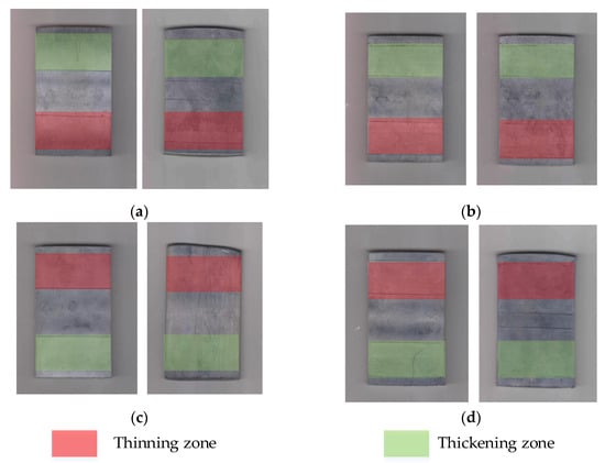
Figure 7.
Photographs of the results of the experiments: (a) photograph of experiment A; (b) photograph of experiment B; (c) photograph of experiment C; (d) photograph of experiment D.
During the experiment, the roll gap of thickening rolling section and thinning rolling section changes continuously, which inevitably leads to the change in rolling force. The rolling forces in stages L1–L5 were continuously collected, and the results are shown in Figure 8.
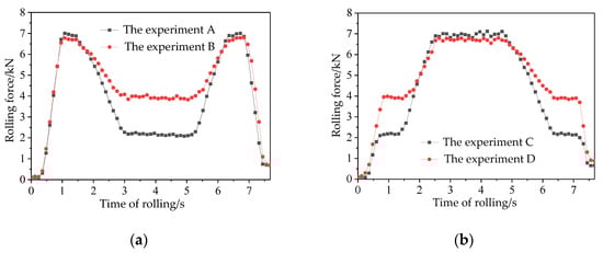
Figure 8.
Graph of measured rolling force: (a) average rolling force measured in experiment A and experiment B; (b) average rolling force measured in experiment C and experiment D.
The contents shown in Figure 8 were analyzed. The pressing amounts at both ends of experiment A and experiment B were larger, while the middle pressing amount was smaller, leading to a rolling force curve presenting a trend of higher at both ends and lower in the middle. Conversely, experiment C and experiment D had smaller pressing amounts at both ends and a larger pressing amount in the middle, so the rolling force curve exhibited a trend of lower at both ends and higher in the middle. Since the rolling force gradually decreased and the thickness gradually increased in thickening rolling, the forward sliding value gradually decreased. In contrast, the thinning rolling forward sliding value showed an increasing trend; thus, under the same conditions, the time required for the same longitudinal length of thickening rolling was longer than that for thinning rolling.
The longitudinal length of the sticking zone is an important parameter of the sticking-sliding model. According to the measured rolling force values, the curve of the length value of the sticking zone along the longitudinal direction can be calculated by applying the Equations (1)–(5) in this paper, as shown in Figure 9.
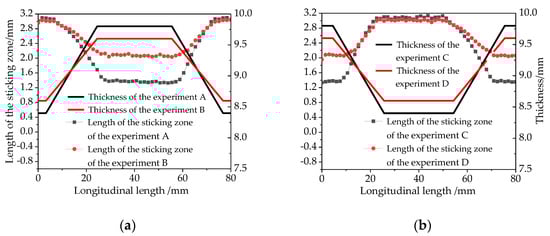
Figure 9.
Graph of length of the sticking zone and thickness: (a) length of the sticking zone and thickness of experiment A and experiment B; (b) length of the sticking zone and thickness of experiment C and experiment D.
As shown in Figure 9, the longitudinal length of the sticking zone is inversely proportional to the thickness of the rolled piece.
According to the measured exit speed of the mill and the circumference speed of the roll, the forward slip value can be calculated by applying Equation (19). This forward slip value can be considered as the measured forward slip value.
The sticking-sliding model described in this paper was applied to calculate the forward slip values at each rolling stage in the experiment. This forward slip value can be considered as the forward slip value of sticking-sliding model. At the same time, the full sliding model was applied to calculate the forward slip values at each rolling stage in the experiment.
The results of the sticking-sliding model, the results of the full sliding model, and the measured results are compared, as shown in Figure 10.
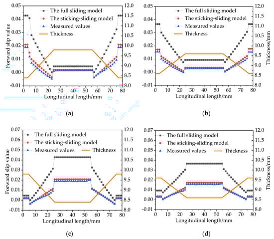
Figure 10.
Comparison graph of forward slip values: (a) comparison graph of forward slip values of experiment A; (b) comparison graph of forward slip values of experiment B; (c) comparison graph of forward slip values of experiment C; (d) comparison graph of forward slip values of experiment D.
As shown in Figure 10, in the multi-stage rolling process, including variable thickness rolling, the sticking-sliding model described in this paper, based on the pre-displacement principle, exhibited a high degree of agreement between the calculated front sliding values and experimental results, with a calculation accuracy significantly higher than that of the full sliding model results.
The longitudinal length of the specimens in each rolling stage is predicted by the sticking-sliding model. The results of the sticking-sliding model, the results of the full sliding model, and the measured results are compared, as shown in Figure 11.
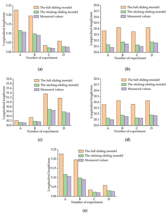
Figure 11.
Comparison plot of the longitudinal length of the rolled pieces at each rolling stage: (a) comparison plot of the longitudinal length of the rolling stage L1, (b) comparison plot of the longitudinal length of the rolling stage L2, (c) comparison plot of the longitudinal length of the rolling stage L3, (d) comparison plot of the longitudinal length of the rolling stage L4, and (e) comparison plot of the longitudinal length of the rolling stage L5.
As shown in Figure 11, the sticking-sliding model was used to calculate the longitudinal length of L1~L5 rolling stage specimens, exhibiting a high degree of agreement with the measured results; its accuracy is significantly higher than that of the full sliding model calculation results. On analyzing the experimental results, the main difference between the sticking-sliding model established based on the pre-displacement principle and the full sliding model is the addition of the sticking zone, which is closer to the actual situation. Since the rolled piece and the roller are relatively stationary within the sticking zone, the longitudinal flow of metal is macroscopically restricted, resulting in the forward sliding values and longitudinal length values calculated using the sticking-sliding model being smaller than the full sliding model’s calculated results. The experimental results also confirmed the rationality and correctness of the sticking-sliding model based on the pre-displacement principle.
6. Conclusions
In this paper, the basic assumptions for analyzing the relative motion between rolled piece and roller in the longitudinal variable thickness rolling process are introduced, the characteristics of longitudinal variable thickness rolling are summarized, the limitations of the existing full sliding model and full sticking model are pointed out, and the purpose and significance of this study are expounded.
Based on the principle of pre-displacement, the deformation zone in the variable thickness rolling process is redefined, and the rolling deformation is divided into three regions according to the relative motion relationship between the rolled piece and the roller, including the forward slip zone, the sticking zone, and the backward slip zone. One of the focuses of this research is to derive the formula of the longitudinal length of the adhesive zone and the formula of the friction force in the rolling deformation zone by combining the calculation method of the limit predisplacement. On this basis, a “sticking-sliding model” which can describe the relative motion between rolled piece and roller in the variable thickness rolling process is proposed. Another research focus of this paper is to analyze variable thickness rolling by using the sticking-sliding model. The concepts of front neutral angle and back neutral angle, which are different from traditional rolling theory, are proposed. By solving the force differential balance equation in the deformation zone, the formula for calculating the neutral angle, the formula for calculating the forward slip value, and the prediction formula for the longitudinal length are derived.
The similarity experiment of lead specimens was carried out by the presetting process in the experimental rolling mill. The experimental results are in good agreement with the calculated results, and the accuracy is higher than that of the traditional rolling theory, which verifies the correctness of the research results.
The sticking-sliding model described in this paper can accurately describe the motion relationship between rolled piece and roller in the variable thickness rolling process. Compared with the traditional rolling model, the new model has the advantages of simple calculation and high precision. This study can provide theoretical support for the analysis of the rolling process with variable thickness and on-line control.
Author Contributions
Literature search, S.Y.; Conceptualization, S.Y. and H.L.; Research idea, S.Y., H.L. and D.W.; Mode design, S.Y., H.L. and D.W.; Software and computing, G.W. and X.C.; Experiment, S.Y., G.W. and X.C.; Data analysis, S.Y., G.W. and X.C.; Figure, S.Y. and X.C.; Writing—original draft preparation, S.Y.; Writing—review and editing, S.Y., H.L. and D.W.; Finalization, S.Y., H.L., D.W., G.W. and X.C.; Project management, S.Y., G.W. and X.C. All authors have read and agreed to the published version of the manuscript.
Funding
This work was supported by the National Natural Science Foundation of China (Grant No. U21A20118).
Data Availability Statement
Not applicable.
Conflicts of Interest
The authors declare no conflict of interest.
References
- Du, P.; Hu, X.Q.; Wang, J.; Liu, X.H. Development and Application of Longitudinal Profiled Plate. Steel Roll. 2008, 25, 47–51. [Google Scholar]
- Yang, S.Y.; Liu, H.M.; Wang, D.C. Differential Analysis and Prediction of Planar Shape at the Head and Tail Ends of Medium-Thickness Plate Rolling. Metals 2023, 13, 1123. [Google Scholar] [CrossRef]
- Ji, Y.F.; Duan, J.R.; Li, H.Y.; Liu, Y.M.; Peng, W.; Ma, L.F. Improvement of Edge Crack Damage of Magnesium Alloy by Optimizing the Edge Curve During Cross Variable Thickness Rolling. Int. J. Adv. Manuf. Technol. 2021, 112, 1993. [Google Scholar] [CrossRef]
- Tan, L.J.; Zhang, S.; Ma, Y.H. Optimization and Application of Plan View Pattern Control Model for Plate Mill. Steel Roll. 2019, 36, 14–19. [Google Scholar]
- Wang, J.; He, C.Y.; Jiao, Z.J. Research and Industrial Practice on Plane Shape Control Model of Medium and Thick Plate; Metallurgical Industry Press: Beijing, China, 2015; pp. 46–60. [Google Scholar]
- Wang, S.; Wang, S.G.; Liu, X.H.; Li, C.S. Experiment and Simulation of Variable Thickness Rolling for 3D-Profiled Blank. J. Mater. Process. Technol. 2021, 290, 116971. [Google Scholar] [CrossRef]
- Lu, S.P.; Wang, Y.F.; Li, Q.; Wang, Z.Y.; Tian, P. Rolling Process Research and Production Practice of LP Plate. Wide Thick. Plate 2020, 26, 23–26. [Google Scholar]
- Wang, Y.Q.; Liu, X.L.; Liu, M.; Ban, H.Y.; Li, J.N. Rolling Technology of Longitudinally Profiled Steel Plate (LP Steel Plate) and Bearing Capacity of LP Flexural Members. Eng. Mech. 2019, 36, 1–12. [Google Scholar]
- Shafiei, E.; Dehghani, K.; Ostovan, F.; Toozandehjani, M. Effect of Microstructure and Texture Evolution During Variable Gauge Rolling on Mechanical Properties of Tailor Rolled Blanks. Met. Mater. Int. 2019, 25, 1378–1387. [Google Scholar] [CrossRef]
- Badparva, H.; Naeini, H.M.; Kasaei, M.M.; Asl, Y.D.; Abbaszadeh, B.; da Silva, L.F.M. Deformation length in flexible roll forming. Int. J. Adv. Manuf. Technol. 2023, 125, 1229. [Google Scholar] [CrossRef]
- Du, P.; Hu, X.Q.; Wang, J.; Liu, X.H.; Wang, G.D. Rolling Parameters for Longitudinal Plate Rolling Process. Iron Steel Res. 2008, 20, 26–31. [Google Scholar]
- Ding, X.K.; Yu, J.M.; Zhang, T.H. Establishment of Digital Model of Plane Shape of Medium and Thick Plate. Iron Steel 1998, 33, 33–37. [Google Scholar]
- Du, P. Research on Rolling Theory and Control Strategy for Longitudinally Profiled Flat Steel. Ph.D. Thesis, Northeastern University, Shenyang, China, 2008. [Google Scholar]
- Rezaei, R.; Naeini, H.M.; Tafti, R.A.; Kasaei, M.M.; Mohammadi, M.; Abbaszadeh, B. Effect of Bend Curve on Web Warping in Flexible roll Formed Profiles. Int. J. Adv. Manuf. Technol. 2017, 93, 3625. [Google Scholar] [CrossRef]
- Liu, H.M. Theory and Application of Three Dimensional Rolling; Science Press: Beijing, China, 1999; pp. 55–83. [Google Scholar]
- Samodurova, M.N.; Karandaeva, O.I.; Khramshin, V.R.; Liubimov, L.V. Calculating Power Parameters of Rolling Mill Based on Model of Deformation Zone with Four-Roll Passes. Machines 2020, 8, 73. [Google Scholar] [CrossRef]
- Zhi, Y.; Liu, X.H.; Sun, T.; Wu, Z.Q.; Zhang, G.J. Investigation of Mathematical Model for the Transition Zone of Tailor Rolled Blank for Variable Gauge Rolling. J. Harbin Eng. Univ. 2017, 38, 602–609. [Google Scholar]
- Liu, Y.M.; Wang, Z.H.; Wang, T. Prediction and Analysis of the Force and Shape Parameters in Variable Gauge Rolling. Chin. J. Mech. Eng. 2022, 35, 88. [Google Scholar] [CrossRef]
- Wang, S.; Hu, X.L.; Wang, X.G.; Chen, J.Q.; Liu, X.H.; Li, C.S. Design and Experiment of V-Shaped Variable Thickness Rolling for Rolled Profiled Strips. J. Mater. Res. Technol.-JMR&T 2021, 15, 4381. [Google Scholar]
- Chen, G.; Wang, X.B. A Soft Measurement and Preise Control Method for Steel Plate Position. Metall. Autom. 2018, 42, 29–33. [Google Scholar]
- Shi, H.J. Research on Metal Flow Law of Ultra-Heavy Plate During Variable Gauge Rolling Process. Ph.D. Thesis, Northeastern University, Shenyang, China, 2018. [Google Scholar]
- Wang, X.G.; Wang, S.; Liu, X.H. Variable Thickness Rolling of Plates Thick in the Middle and Thin on the Sides. J. Mater. Process. Technol. 2020, 277, 116432. [Google Scholar] [CrossRef]
- Bogatov, A.A.; Nukhov, D.S.; P’yankov, K.P. Finite-element Modeling of Plate-rolling. Metallurgist 2015, 59, 113. [Google Scholar] [CrossRef]
- Jiao, Z.J.; He, C.Y.; Gao, S.W.; Wang, X.; Zhang, Y.X.; Hao, L. Application of Variable Gauge Rolling Technology for Plate to Reduce the Head Impact. ISIJ Int. 2023, 63, 660. [Google Scholar] [CrossRef]
- Liu, X.H.; Zhang, G.J. Force Equilibrium Differential Equations for Variable Gauge Rolling. Iron Steel Res. 2012, 24, 10–14. [Google Scholar]
- Sun, J.N.; Zhang, C.Y.; Chen, C.; Huang, H.G. Numerical Simulation of Rolling Process of Three-layer Symmetrical Bimetallic Composite Plate with Variable Thickness. J. Univ. Sci. Technol. Liaoning 2017, 40, 91–97. [Google Scholar]
- Sun, J.N.; Chem, C.; Huang, H.G.; Zhang, C.Y.; Wang, S. Rolling Force Model of Longitude Profile LP Plate Based on E Orowan Differential Equation. Iron Steel 2017, 52, 37–42. [Google Scholar]
- Kragelsky, I.V. Friction and Wear Calculation Methods; Pergamon Press: Oxford, UK, 1982; pp. 94–137. [Google Scholar]
- Zhao, Q.L.; Liu, X.H.; Sun, X.K. Analysis of Mechanical Parameters of Asymmetrical Rolling Dealing with Three Region Percentages in Deformation Zones. Materials 2022, 15, 1219. [Google Scholar] [CrossRef]
- Sun, X.K.; Liu, X.H.; Wang, J.; Qi, J.L. Analysis of Asymmetrical Rolling of Strip Considering Percentages of Three Regions in Deformation Zone. Int. J. Adv. Manuf. Technol. 2020, 110, 763–775. [Google Scholar] [CrossRef]
- Wang, Y.L.; Zhu, A.R.; Fan, M.D. Calculation Principle of Friction and Wear; China Machine Press: Beijing, China, 1988; pp. 158–175. [Google Scholar]
- Barbu, C.D.; Sandru, N. Mathematical Approach of the Flat Rolling Problem and New Aspects Concerning the Geometry of the Deformation Zone. Proc. Rom. Acad. Ser. Math. Phys. Tech. Sci. Inf. Sci. 2019, 20, 77. [Google Scholar]
- Bian, Y.H.; Liu, H.M. Solving the Contact Friction In Cold Sheet and Strip Rolling by Using Preparatory Displacement Principle. Iron Steel Res. 1994, 6, 29–35. [Google Scholar]
- Zhang, X.P.; Qin, J.P. Rolling Theory; Metallurgical Industry Press: Beijing, China, 2006; pp. 127–141. [Google Scholar]
Disclaimer/Publisher’s Note: The statements, opinions and data contained in all publications are solely those of the individual author(s) and contributor(s) and not of MDPI and/or the editor(s). MDPI and/or the editor(s) disclaim responsibility for any injury to people or property resulting from any ideas, methods, instructions or products referred to in the content. |
© 2023 by the authors. Licensee MDPI, Basel, Switzerland. This article is an open access article distributed under the terms and conditions of the Creative Commons Attribution (CC BY) license (https://creativecommons.org/licenses/by/4.0/).