Abstract
Conventional methods for producing porous metals involve the use of chemicals such as thickeners and foaming agents under high temperatures and pressures. However, these methods are costly and pose a risk of dust explosion. Thus, the objective of this research is to achieve the cost-effective and safe production of porous metals by introducing microbubbles generated by ultrasonic oscillation into the molten metal. One end of an ultrasonic horn was inserted into three different molten metals—white metal, Pb-free solder, and zinc—and microbubbles were generated at the horn end by the strong ultrasonic oscillation in the molten metals. The microbubbles that contained molten metal changed phase to porous metal through solidification, and the diameter, porosity, and stress–strain curve of the generated porous metals were measured. The results indicate that the porosity of white metal, Pb-free solder, and zinc foams reached 54%, 76%, and 48%, respectively, and these porous metals had many micropores less than 1 mm in diameter. It was also observed that the higher the melting point, the larger the pore diameter and the lower the porosity. Furthermore, in the case of white metal, a plateau region of large deformation at constant stress was observed in the stress–strain curve.
1. Introduction
Porous metals have garnered significant attention as functional composites that merge the properties of metals and porous materials [1]. Their elevated porosity enables the creation of ultralight materials that are even lighter than the lightest alloys of Mg and Al. Therefore, their application is anticipated in industrial commodities such as structural components and automobile impact absorbers, for which the expected requirements encompass rigidity, potency, impact mitigation, and vibration management, in addition to weight diminution [2].
Empirical studies have demonstrated that porous metals have numerous excellent properties, including shock absorption, thermal insulation, sound deadening, and vibration damping [3,4,5], as well as a series of mechanical properties [6] and electrochemical properties [7]. For example, Selivanov et al. reported that aluminum alloys with a porous structure are effective as shock absorbers to absorb the impact of a spacecraft landing [8]. Duan et al. also proposed porous metal panels a new lightweight sound-absorbing material, which were proven to have good sound-absorbing properties and exhibit practicality [9]. Yang et al. succeeded in effectively improving the sound absorption properties of porous metals by means of a composite structure, achieving optimum values for sound absorption [10]. Many techniques for the fabrication of porous metals exist, which are contingent on factors such as structural intricacy, pore count, pore diameter, porosity, and pore morphology. Certain approaches involve the incorporation of foaming agents or thickeners into the molten metal, whereas others entail the blending of a foaming aid with metal powder, followed by solidification [11,12]. These techniques are complicated and expensive due to the high material costs of foaming and thickening agents. The possibility of dust explosion should also be considered in the case of methods using metal powders [13]. To solve these problems, porous metal fabrication technology using microbubbles was proposed. Microbubbles with diameters of less than 50 μm have attracted considerable attention because of their properties such as a large surface area per unit volume, low rising velocity, and self-pressurization due to surface tension. Conventionally, microbubbles are generated by the following two types of techniques: generation using gas release from a small orifice and generation based on hydrodynamic instability. Microbubble generation from a small needle or porous media is simple because the size of the microbubbles can be controlled by varying the orifice size [12]. Two-fluid nozzles such as a swirl flow nozzle can be used to generate microbubbles with diameters of less than 100 μm at high gas flow rates [14]. The generation of microbubbles is often achieved by introducing gas into a porous medium or disturbing the gas–liquid interface using shear flow [14,15]. However, these methods are not effective when applied to highly viscous fluids, such as high-temperature molten metals, due to the risk of clogging the porous media or damaging the pump used to generate the shear flow. Makuta et al. devised a method for generating microbubbles in liquids using a generator equipped with a cylindrical hollow ultrasonic horn that oscillates at 19.5 kHz with a 40 μm amplitude [16]. This method can be easily adapted to high-temperature liquids and liquids with greater viscosity than water, generating microbubbles with a diameter of approximately 20 μm [17]. However, the ultrasonic transducer connected to the horn is unsuitable for high-temperature applications and can only be employed at temperatures below 100 °C. Therefore, past studies have produced only porous metals with a melting point of 78 °C, a porosity of 70%, and a pore size of up to 100 μm [18].
In porous metal fabrication technology, the metals are subjected to a processing technique that uses small bubbles known as millibubbles and microbubbles. Millibubbles, whose dimensions are on the millimeter scale, exhibit traits that are comparable to those of bubbles commonly observed in our day-to-day experiences. They ascend swiftly in water and ultimately burst and dissipate at the water surface. Conversely, bubbles with diameters of 50 μm or less demonstrate characteristics that are distinct from those of ordinary bubbles and are referred to as microbubbles to distinguishes them from their larger counterparts. The primary characteristics of microbubbles include a substantial gas–liquid interfacial area per unit volume [19], a slow ascent rate within water [20], the self-pressurization phenomenon, and distinctive surface potential characteristics [21]. Especially for a slow ascent rate in liquid, they are expected to be effective for the fabrication of porous structures with molten metal.
In this study, we tested the feasibility of using white metal, which has a low melting point and is readily available, to produce porous metals. We also verified the effect of the melting point on the formation and structure of porous metals. For this purpose, similar experiments were performed with metals with higher and lower melting points than white metal.
2. Materials and Methods
2.1. Materials
The base metal we used for the production of porous metal was white metal (WJ-1, Sn-6Sb-4Cu, Fujimetal Industry Co., Ltd., Ota, Japan). White metal is an alloy consisting of Sn, Sb, and Cu. To clarify the effect of the melting point on the fabrication of porous metals, additional experiments were conducted with a lead-free solder alloy and zinc. According to thermal analysis by DSC (DSC-60 Plus, Shimadzu Co., Ltd., Nakagyo, Japan), the melting point and solidification point of the white metal were 239 °C and 223 °C, respectively, and those of the lead-free solder alloy (LLS-138, Sn-58Bi, SOLDER COAT Co., Ltd., Midori, Japan; hereafter referred to as “LLS-138”) were 140 °C and 138 °C, respectively. As for the zinc (granular zinc, E-material Co., Ltd., Tachikawa, Japan), the melting point was 419 °C according to the product information.
2.2. Microbubble Generator
We utilized an ultrasonic microbubble generator with a Langevin transducer (UH600-SH, SMT Co., Ltd., Katsushika, Japan). We used an electric piezoelectric ultrasonic transducer to generate ultrasonic waves by capitalizing on the expansion and contraction of the piezoelectric material.
A hollow ultrasonic horn featuring an internal flow channel that enables the passage of gas was attached to the transducer. Supplying the gas through the horn’s inner pathway amplified the ultrasonic oscillation of the horn, thereby generating many tiny bubbles at the end of the horn. As this method does not require the circulation of liquid, the generation of microbubbles can be achieved through the use of a hollow ultrasonic horn, regardless of the nature of the liquid. Consequently, we adopted this system to effectively generate microbubbles within the molten metal at elevated temperatures.
The microbubble generator consists a 19.5 kHz ultrasonic transducer, an ultrasonic horn that contains a cylindrical gas flow pathway with an inner diameter of 3 mm, and an orifice tip screwed to the end of the horn. Figure 1a shows the hollow ultrasonic horn with the orifice tip, and Figure 1b,c show the shape of the orifice tip. The ultrasonic waves generated by the transducer are amplified at the step horn. Upon introduction of gas into the horn while it is submerged in a liquid, the interface between the gas and liquid undergoes vibration and induces the formation of surface waves. This process leads to the segregation of the gas phase, resembling its envelopment by the liquid phase, thereby generating microbubbles. Moreover, a cooling system is used for liquids hotter than 100 °C, including white metal. A cooling device with water circulating inside it is mounted between the transducer and the horn. The cooling system counteracts the heat transmitted from the horn and prevents heat transfer to the transducer.
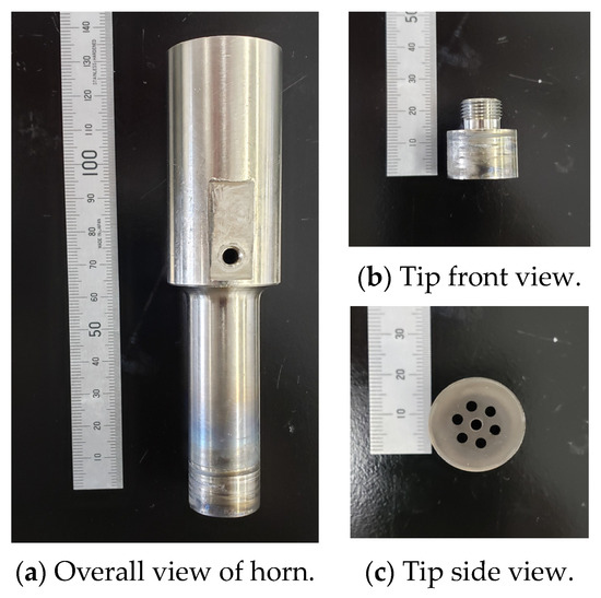
Figure 1.
Photographs of the ultrasonic horn: (a) overall view; (b) front view; (c) side view of tip.
Figure 2 shows the generation of microbubbles in water using an ultrasonic wave under the conditions of a flow rate of 100 mL/min, a frequency of 19.5 kHz, and an ultrasonic amplitude of 40 μm. The image was taken using a high-speed camera (FASTCAM SA1.1, PHOTRON Co., Ltd., Chiyoda, Japan) and a 2X objective lens (M Plan Apo 2X, Mitutoyo Co., Ltd., Kawasaki, Japan). Immediately after the ultrasonic oscillation, that is, at 0 ms, the bubbles (the black areas in Figure 2) exist in a clustered state. They then undergo deformation and division to form smaller bubbles. In Figure 2, the photograph at 20 ms captures the moment when the bubbles become finer, as indicated by the red dashed lines around the bubbles.
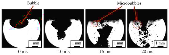
Figure 2.
Microbubble generation mechanism using a hollow ultrasonic horn (flow rate, 100 mL/min; frequency, 19.5 kHz; amplitude, 40 μm).
2.3. Fabrication Process for Porous Metals
Figure 3 shows the experimental apparatus employed for the generation of the porous metal, and Table 1 shows the corresponding experimental conditions. The experimental apparatus comprises a small furnace for heating the molten metal and a microbubble generator that is equipped with an ultrasonic horn. The process of producing the porous metal is as follows:
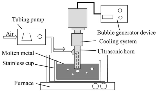
Figure 3.
Experimental apparatus used for fabrication of porous metal and the cooling system.

Table 1.
Experimental conditions.
- Sample metal in the amount of 200 g is placed into a stainless-steel cup measuring φ40 mm × 35 mm; then, the cup is placed in a furnace (FT-01P, FULL-TECH Co., Ltd., Yao, Japan);
- The tip of the ultrasonic horn is inserted into the molten metal to a depth 12 mm below the surface. Air is then blown through the orifices at the tip of the horn into the molten metal at a rate of 100 mL/min using a tube pump (Masterflex 7554-90, Cole-Parmer Instrument Co., Ltd., Vernon Hills, IL, USA);
- The samples of LLS-138, white metal, and zinc are heated to 300, 500, and 550 °C, respectively. Except in the case of zinc, due to the risk of its thermal ignition, silicone oil is filled in the test section to suppress the temperature difference between the top and bottom of the molten metal;
- Ultrasonic oscillation is applied for 10 min to generate microbubbles in the molten metal;
- The stainless-steel cup holding the foamed molten metal is extracted from the furnace and cooled in cold water at 10 °C–15 °C.
3. Results and Discussion
3.1. Fabrication of Porous Metals
Figure 4 shows consecutive images at 0 s, 5 s, 30 s, 1 min, and 6 min during the generation process for the porous metals. When the ultrasonic horn begins to oscillate with the gas supply at 0 s, small bubbles in molten metal gradually move upward because of their buoyancy, as shown in the images at 5 s, 30 s, and 1 min; they push the metal surfaces as a thick foam layer, as shown in the image at 6 min. The porous metal is finally generated by the phase change in the molten metal foam due to cooling.
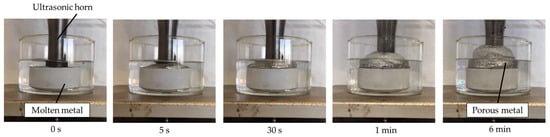
Figure 4.
Porous metal formed by blowing microbubbles in molten white metal.
3.2. Internal Structure of Fabricated White Metal
The sample was cut by a contour machine (BS-23, Toyo Associates Co., Ltd., Musashimurayama, Japan), and the cut surface was polished with #240, #400, #800, #1000, and #2000 waterproof sandpaper in ascending order. The cross section of the cut and polished porous metal was observed under an optical microscope (VHX-2000, KEYENCE Co., Ltd., Higashiyodogawa, Japan). Figure 5 shows the cross-sectional surfaces of the fabricated porous white metal, and Figure 5b shows a magnified image of the area indicated by the red square in Figure 5a, which shows the whole image. Differently shaped and sized black spots in the upper and middle area of Figure 5a can be identified, and almost no spots appear in the bottom area as the generated bubbles move upward through buoyancy. Figure 5b shows that many variously sized pores, including those with a size less than 1 mm, exist independently, which means the fabricated porous metals have a closed-cell structure. The pores with a spherical shape are thought to be due to microbubbles having with a strong surface tension that have solidified with their spherical shapes. Non-spherical pores are thought to be solidified by relatively large bubbles that form from the coalescence of microbubbles or insufficient gas breakup at the end of the horn.
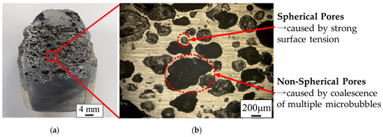
Figure 5.
Cross section of porous white metal observed by an optical microscope. (a) Overall cross-sectional view. (b) Magnified cross-sectional view.
3.3. Pore Size of Fabricated White Metal
The pore distribution was obtained by image processing with 15 cross-sectional images taken by an optical microscope. In this image processing, bright areas and dark circular areas in the cross-sectional image were regarded as metal wall and pores, respectively, and the pore size was assumed to be the area equivalent diameter of the dark circular area. The maximum, minimum, and standard deviation of the measured pore size (n = 694) were 1070 µm, 28 µm, and 180 µm, respectively. Figure 6 shows the pore size distribution of white metal as analyzed by the software (Mac-View Ver4, Mountech, Shinjyuku, Japan), in which equivalent diameters are calculated from the area of the pore opening in the cross-sectional image shown in Figure 5a. The distribution of the pore diameters exhibited its highest peak within the range of 300 to 400 μm. Furthermore, over half of all the pores measured by the software have a diameter of less than 200 μm. The average pore size of the porous metal was 220 μm in equivalent diameter. This size exceeds 20 μm, which is the average size of the microbubbles generated in the water by the device. For the generation of microbubbles in water from the ultrasonic horn, microbubbles are generated by primary breakup of the gas–liquid interface near the horn end and secondary breakup, in which the bubbles from the primary breakup are further miniaturized by resonance of the bubbles [16]. Equation (1) shows the relationship between resonance frequency and bubble diameter [22].
where f is the resonance frequency, D0 is the bubble diameter, κ is the specific heat ratio of the gas inside the bubble, P0 is the atmospheric pressure, and σ is the surface tension coefficient.
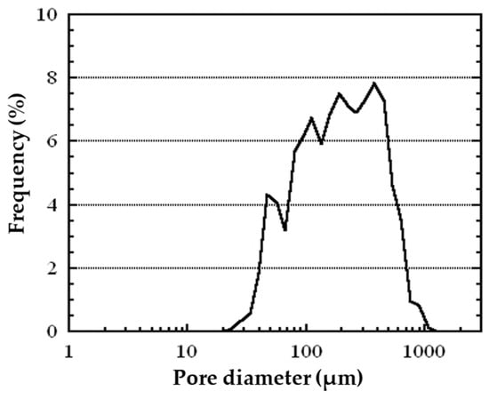
Figure 6.
Pore diameter distribution of the fabricated closed-cell porous white metal.
Substituting the physical properties of water and the molten white metal [23], the resonance bubble diameter in the case of 20 kHz ultrasonic oscillation is about 330 μm in the case of water and 110 μm in the case of white metal, indicating that the size of the resonance bubble is considerably smaller in the case of white metal. Therefore, in the case of water, when bubbles of about 300 μm, which is close to the resonance diameter, are generated from the horn, they are miniaturized by secondary breakup due to bubble resonance, whereas in the case of molten white metal, bubbles of the same size are much larger than the resonance bubble diameter in water; therefore, secondary breakup does not occur easily. In addition, the generated bubbles become larger with time and move away from the resonance diameter due to the heating and expansion of the gas inside. Since secondary breakup rarely occurs in the case of molten metal, the frequency peak of pore diameter in porous metal is much larger than that of the bubble diameter in water. Nevertheless, in comparison with the pores generated through conventional methods, which generally possess average pore diameters of more than 1 mm, the observed pores are significantly smaller [24,25,26].
3.4. Relationship between Porosity and Compressive Deformation of White Metal
The characteristics of porous metals are influenced by their porosity, which denotes the ratio of the pore volume to the total volume of the metal [27]. To measure the porosity of the generated porous metal, the metal was placed in a measuring cylinder filled with water; the volume increase in the cylinder was measured by the rising water level, and the porosity was calculated according to this volume and mass. Equation (2) presents the porosity equation.
where ρA (g/mL) is the density of the base metal and ρB (g/mL) is the density of the metal after foaming. In the case of white metal, a value of ρA = 7.38 g/mL was used in the calculation. The value for ρB was obtained by dividing the mass of fabricated porous metal by the volume. In this case, the porous white metal had a porosity of 54%.
porosity = (ρA − ρB)/ρA,
Porosity is closely related to material performance, especially the mechanical properties [6,28]. Therefore, a compression test was performed using a universal testing machine (Autograph AG50KGN, manufactured by Shimadzu Co., Ltd., Nakagyo, Japan) based on ISO 13314:2011 to confirm the performance of porous metals [29]. Compression tests were carried out on 10 × 10 × 10 mm cube specimens cut out from fabricated porous metal. Figure 7 shows the results of the compression test (stress–strain curve) on white metal, where the horizontal axis is the strain and the vertical axis is the stress. The black dashed line in Figure 7 represents the result for nonporous metals, and the red line represents the result for porous metals. In the nonporous case, the slope of the stress–strain curve is nearly constant until the high-stress region. In the porous metal, the slope changes considerably with an increase/decrease in stress. When the stress is between 5 and 12 N/mm, the deformation of strain is the largest; then, the deformation gradually decreases as the stress increases and becomes linear. The region in which the strain changed with a slight changed in stress is called the plateau region. On the other hand, the yield stress of the non-porous specimen was about 50 MPa, which is considerably larger than the plateau stress of the porous metal specimen.
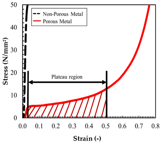
Figure 7.
Stress–strain curve of white metal in compression test.
There is no plateau region in low-porosity samples, and a plateau region exists when the porosity is 45% or greater [30]. It can be inferred that the white porous metal fabricated in this study has compressive properties similar to those of ordinary porous metal, with excellent specific stiffness and shock absorption properties [31] because the porosity of the white porous metal reached 54%, and a plateau region also appeared, as shown in Figure 7.
The plateau region of the stress–strain curves obtained from the compression tests is an indicator of the ability of the porous metals to effectively absorb impact energy when used as shock absorbers [32]. The appearance of this region is due to the presence of many small pores. The size of the plateau region and the deformability of the metals increase with increased porosity [5]. Therefore, by properly adjusting the porosity of the metals, the impact energy of car crashes can be effectively absorbed by the breaking of the porous metal.
3.5. Application to Other Metal Alloys (LLS-138 and Zinc)
To investigate the effect of the melting point, porous metals of LLS-138 (Sn-58Bi, melting point 138 °C) and zinc (Zn, melting point 419 °C) were fabricated using the processing techniques described in Section 2.2 and Section 2.3.
Figure 8 shows a cross-sectional image of porous metals using LLS-138 (Figure 8a), white metal (Figure 8b), and zinc (Figure 8c). The center, left, and right of each section in Figure 8 are images of the overview. The pores of all metals in Figure 8 have various shapes and sizes; the number of pores generated in LLS-138 is greater than the number of pores in zinc and white metals, and the pore size in LLS-138 is smaller than in zinc and white metal.
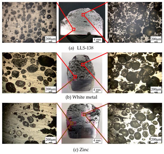
Figure 8.
Cross-sectional image of the fabricated porous metals.
Figure 9 illustrates the distribution of pore sizes in the three different types of porous metals produced using white metal, LLS-138, and zinc. It is evident that pores with a diameter of less than 200 μm dominate in all three samples. Moreover, the peaks in the pore size distribution curve correlate with the melting temperature of the alloys, and the alloys have progressively larger peaks in the order of LLS-138, white metal, and zinc.
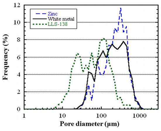
Figure 9.
Pore diameter distribution of the fabricated closed-cell porous metals using zinc, white metal, and LLS-138.
Table 2 presents the average pore diameter and porosity values for the three types of porous metals, showing a decrease in porosity as the melting point increases.
Table 2.
Measurement of porous metals fabricated using alloys with different melting points.
The increase in the average pore size with the increase in melting point might have caused a shift from optimum ultrasonic oscillation length due to the thermal expansion of the titanium alloy, in addition to volume expansion of the bubbles in the hot molten metals. Because ultrasonic horns amplify oscillation by forming standing waves between the surface connected to the transducer and the end of the horn, the distance between the transducer and the end of the horn is important. Here, the coefficient of linear expansion of the titanium alloy is 8.8 × 10⁻⁶ [/°C], and the horn (almost 135 mm) extends 0.56 mm with respect to 470 °C. Therefore, it is thought that sufficient miniaturization did not occur from the position shift from resonance with the increase in temperature, especially in zinc, because of the extension of the horn. In addition, microbubbles in molten metal are made from air at room temperature and expand in a high-temperature environment. As for the compression test, except for white metal, test specimens with uniformly dispersed voids for the compression test could not be obtained in sufficient quantity due to large voids or cracks from one surface to the opposite surface of the cubic specimen.
In summary, the porosities of white metal, LLS, and zinc reached 54%, 76%, and 48%, respectively, which confirms that the presence of many pores with diameters of 1 mm or less. It also shows that the higher the melting point, the larger the pore size and the lower the porosity.
4. Conclusions
A pioneering approach involving the utilization of ultrasonic microbubbles was devised to manufacture porous metals. These metals have garnered significant attention for their wide-ranging application as functional composite materials and energy-absorbing substances. By employing this innovative method, porous metals were produced from alloys with various melting points. The porous metals were subsequently subjected to analysis to assess their pore size and porosity. The ensuing findings can be summarized as follows:
- Utilizing an ultrasonic microbubble generator enables the creation of closed-cell porous metals featuring microscale pores, even if the melting point is 419 °C;
- Many small pores with diameters of less than 1 mm were observed in the porous metal after formation;
- In molten white metal, the bubbles generated from the ultrasonic horn were larger than those of water because secondary breakup was less likely to occur due to the decrease in resonance bubble diameter and thermal expansion of the bubbles;
- The developed method allows for the fabrication of porous metals that exhibit porosities exceeding 45%, provided that the melting point is 419 °C or less;
- The higher the melting point, the larger the pores and the lower the porosity.
Based on these results, the proposed method using an ultrasonic horn is expected to generate microbubbles in high viscous molten metal containing a thickening agent for preferred porous metal fabrication. In the future, we will perform compression and acoustic tests on the porous metals we have produced so far. Porous metal formation by microbubbles has not yet been realized for magnesium alloys and aluminum alloys, which are practical metals. To enable the formation of these metals, it is necessary to elucidate the mechanism of porous metal formation and optimize the experimental conditions.
Author Contributions
Conceptualization, T.M.; Methodology, Y.S. and T.M.; Investigation, Y.S., H.N. and T.M.; Resources, W.X.; Data curation, W.X. and T.M.; Writing—original draft, Y.S., W.X. and T.M.; Visualization, Y.S.; Supervision, T.M.; Project administration, T.M. All authors have read and agreed to the published version of the manuscript.
Funding
This paper is based on results obtained in project JPNP2004, which was subsidized by the New Energy and Industrial Technology Development Organization (NEDO).
Data Availability Statement
Not applicable.
Conflicts of Interest
The authors declare no conflict of interest.
References
- Liu, P.S.; Chen, G.F. Porous Materials; Butterworth-Heinemann: Oxford, UK, 2014. [Google Scholar]
- Yuan, L.; Ding, S.; Wen, C. Additive manufacturing technology for porous metal implant applications and triple minimal surface structures: A review. Bioact. Mater. 2019, 4, 56–70. [Google Scholar] [CrossRef] [PubMed]
- Mabuchi, M.; Yamada, Y.; Wen, C. Compressive properties of metallic cellular materials. Foundry Eng. 2002, 74, 822–827. [Google Scholar]
- Suzuki, R.; Kitazono, K. Effect of graded pore distribution on thermal insulation of metal foam. J. Jpn. Inst. Met. 2008, 72, 758–762. [Google Scholar] [CrossRef]
- Hakamada, M.; Mabuchi, M. Fabrication by spacer method and evaluation of porous metals. J. Jpn. Inst. Light Met. 2012, 62, 313–321. [Google Scholar] [CrossRef]
- Liu, P.S.; Ma, X.M. Property relations based on the octahedral structure model with body-centered cubic mode for porous metal foams. Mater. Des. 2019, 188, 108413. [Google Scholar] [CrossRef]
- Egorov, V.; O’Dwyer, C. Architected porous metals in electrochemical energy storage. Curr. Opin. Electrochem. 2020, 21, 201–208. [Google Scholar] [CrossRef]
- Selivanov, V.V.; Silnikov, M.V.; Markov, V.A.; Popov, Y.V.; Pusev, V.I. Using highly porous aluminum alloys and honeycomb structures in spacecraft landing gear. Acta Astronaut. 2021, 180, 105–109. [Google Scholar] [CrossRef]
- Duan, H.; Shen, X.; Yin, Q.; Yang, F.; Bai, P.; Zhang, X.; Pan, M. Modeling and optimization of sound absorption coefficient of microperforated compressed porous metal panel absorber. Appl. Acoust. 2020, 166, 107322. [Google Scholar] [CrossRef]
- Yang, X.; Shen, X.; Duan, H.; Zhang, X.; Yin, Q. Identification of Acoustic Characteristic Parameters and Improvement of Sound Absorption Performance for Porous Metal. Metals 2020, 10, 340. [Google Scholar] [CrossRef]
- Baumgaertner, F.; Duarte, I.; Banhart, I. Industrialization of powder compact toaming process. Adv. Mater. 2000, 2, 168–174. [Google Scholar] [CrossRef]
- Atwater, M.A.; Guevara, L.N.; Darling, K.A. Tschopp, Solid State Porous Metal Production: A Review of the Capabilities, Characteristics, and Challenges. Adv. Eng. Mater. 2018, 20, 1700766. [Google Scholar] [CrossRef]
- Eckhoff, R.K.; Li, G. Industrial Dust Explosions, A Brief Review. Appl. Sci. 2021, 11, 1669. [Google Scholar] [CrossRef]
- Terasaka, K.; Tsuge, H. Bubble formation under constant-flow conditions. Chem. Eng. Sci. 1993, 48, 3417–3422. [Google Scholar] [CrossRef]
- Iguchi, M.; Kondoh, T.; Uemura, T.; Yamamoto, F.; Morita, Z. Bubble and liquid flow characteristics in a cylindrical bath during swirl motion of bubbling jet. Exp. Fluids 1994, 16, 255–262. [Google Scholar] [CrossRef]
- Makuta, T.; Aizawa, Y.; Suzuki, R. Sonochemical reaction with microbubbles generated by hollow ultrasonic horn. Ultrason. Sonochemistry 2013, 20, 997–1001. [Google Scholar] [CrossRef] [PubMed]
- Makuta, T.; Suzuki, R.; Nakao, T. Generation of microbubbles from hollow cylindrical ultrasonic horn. Ultrasonics 2013, 53, 196–202. [Google Scholar] [CrossRef] [PubMed]
- Katayose, A.; Yokose, R.; Makuta, T. Fabrication of closed-cell porous metals by using ultrasonically generated microbubbles. Mater. Lett. 2016, 185, 211–213. [Google Scholar] [CrossRef]
- Tsuge, H. The Latest Technology on Microbubbles and Nanobubbles; CMC Publishing, Co.: Chiyoda, Japan, 2010; Volume 2, pp. 57–58. [Google Scholar]
- Takahashi, M. The Latest Technology of Microbubbles; NTS Inc.: New York, NY, USA, 2006; pp. 3–13. [Google Scholar]
- Takahashi, M. Zeta Potential of microbubbles in aqueous solutions: Electrical properties of the gas-water interface. J. Phys. Chem. B 2005, 109, 21858–21864. [Google Scholar] [CrossRef]
- Plesset, M.S.; Prosperetti, A. Bubble Dynamics and Cavitation. Annu. Rev. Fluid Mech. 1977, 9, 145–185. [Google Scholar] [CrossRef]
- Plevachuk, Y.; Hoyer, W.; Kaban, I.; Köhler, M.; Novakovic, R. Experimental study of density, surface tension, and contact angle of Sn–Sb-based alloys for high temperature soldering. J. Mater. Sci. 2010, 45, 2051–2056. [Google Scholar] [CrossRef]
- Itoh, M.; Nishikawa, T.; Morimoto, K.; Akiyama, S.; Ueno, H. Development of foamed aluminum “ALPORAS”. J. Jpn. Inst. Met. 1987, 26, 311–313. [Google Scholar]
- Kobashi, M.; Tanahashi, S.; Kanetake, N. Foaming behavior of porous aluminum by heating of precursors of Al-TiH2 powder. J. Jpn. Inst. Light Met. 2003, 53, 427–432. [Google Scholar] [CrossRef]
- Kränzlina, N.; Niederberger, M. Controlled fabrication of porous metals from the nanometer to the macroscopic scale. Mater. Horiz. 2015, 2, 359–377. [Google Scholar] [CrossRef]
- Torres-Sanchez, C.; Al Mushref, F.R.A.; Norrito, M.; Yendall, K.; Liu, Y.; Conway, P.P. The effect of pore size and porosity on mechanical properties and biological response of porous titanium scaffolds. Mater. Sci. Eng. C 2017, 77, 219–228. [Google Scholar] [CrossRef] [PubMed]
- Ashby, M.F.; Evans, T.; Fleck, N.A.; Hutchinson, J.W.; Wadley, H.N.G.; Gibson, L.J. Metal Foams: A Design Guide; Butterworth-Heinemann: Oxford, UK, 2000. [Google Scholar]
- ISO 13314:2011; Mechanical Testing of Metals—Ductility Testing—Compression Test for Porous and Cellular Metals. ISO (International Organization for Standardization): Geneva, Switzerland, 2011.
- Nishi, S.; Makii, K.; Ariga, Y.; Hamada, T.; Naito, J.; Miyoshi, T. The manufacturing process and mechanical properties of porous aluminum. R&D Kobe Steel Eng. Rep. 2004, 54, 89–94. [Google Scholar]
- Hakamada, M.; Asao, Y.; Kuromura, T.; Chen, Y.; Kusuda, H.; Mabuchi, M. Density dependence of the compressive properties of porous copper over a wide density range. Acta Mater. 2007, 55, 2291–2299. [Google Scholar] [CrossRef]
- Banhart, J. Manufacture, characterisation and application of cellular metals and metal foams. Prog. Mater. Sci. 2001, 46, 559–632. [Google Scholar] [CrossRef]
Disclaimer/Publisher’s Note: The statements, opinions and data contained in all publications are solely those of the individual author(s) and contributor(s) and not of MDPI and/or the editor(s). MDPI and/or the editor(s) disclaim responsibility for any injury to people or property resulting from any ideas, methods, instructions or products referred to in the content. |
© 2023 by the authors. Licensee MDPI, Basel, Switzerland. This article is an open access article distributed under the terms and conditions of the Creative Commons Attribution (CC BY) license (https://creativecommons.org/licenses/by/4.0/).