Abstract
Wire-beam, potentiodynamic polarization, electrochemical impedance spectroscopy and surface corrosion morphology analysis techniques were used to investigate the corrosion characteristics of 304 stainless steel (304SS) specimens subjected to different degrees of fouling; these analyses were conducted to clarify the corrosive effects of biofilms and barnacles. The experimental results indicated that the gradual thickening of the biofilm reduces the corrosion rate of 304SS (Icorr = 0.0677 μA/cm2). Mature biofilm acts as a barrier and significantly increases the protection of the substrate (Z = 905,000 Ω·cm2). The corrosion mechanisms of 304SS fouled with barnacles at various stages of growth are distinct: the corrosion rates of the microelectrodes fouled by living and recently dead barnacles are low because the overall structure is still intact. This structure creates a closed environment between the barnacles and the metal, limiting the transfer of corrosive factors from the outside to the inside. Despite the influences of corrosive bacterial decomposition, the Ecorr values of recently dead barnacles dramatically decrease to −668.8 mV. The microelectrode covered by the empty-shell barnacles corrodes heavily. Bacteria decompose the barnacle body and calcite shell, and glue damages their originally closed structures. Direct contact between the metal and reactive ions occurs, resulting in the continuous ingress of Cl− into the cracks, which intensifies crevice corrosion.
1. Introduction
The world is undergoing a substantial energy transition with an increasing share of intermittent sources of energy, such as wind [1]. The construction of offshore wind farms is a highly effective initiative for the promotion of the energy transition. Relative to onshore wind power, offshore wind power has the advantages of a high power-generating efficiency, suitability for large-scale development, and abundant wind resources [2]. However, the fact that wind farms pass through several marine zones indicates that their corrosion process is influenced by various factors, such as temperature, dissolved oxygen, seawater pressure, and fouling organisms [3]. Exposure to harsh marine environments is not a simple matter for the construction and duration of offshore structures, which are mainly composed of steel [4].
Research on the effects of marine fouling organisms on the corrosion behaviors of steel surfaces is a popular topic of interest. Marine fouling organisms are a general term for animals, plants, and microorganisms that adhere to the surfaces of marine facilities [5]. According to the difference in the form of attachment, biofouling is divided into microbial and macrobial fouling. After natural colonization, fouling organisms are adsorbed on the surface of the substrate, leading to certain problems, such as increased resistance to ship navigation, clogging of transport pipes and reduced heat transfer efficiency, which affect the performance and age of the facilities [6,7,8,9].
Consequently, researchers have conducted numerous studies on fouling organisms and found that different bacterial species play distinct roles in microbial corrosion. Sulfate-reducing bacteria (SRB), as the main mechanism of microbiologically influenced corrosion (MIC), have dominant influences on localized corrosion problems [10]. SRB not only increases the pit penetration rate to promote localized corrosion in carbon steel [11], but for duplex stainless steels with desirable mechanical properties and excellent resistance to stress corrosion cracking, SRB is also able to preferentially attach and corrode the austenitic phase of the DSS, which has the high nickel and nitrogen contents [12,13]. At the same time, the aerobic Pseudomonas aeruginosa, as the pioneer colonizer in the process of biofilm formation, could reduce the corrosion resistance of the DSS [14]. For 304 stainless steel, Pseudomonas aeruginosa also promotes the bioreductive dissolution of iron oxides in the passive film and further leads to the occurrence of pitting corrosion [15]. Moreover, the types of corrosion caused by different macroscopic fouling are unique. Typical macrofouling is divided into soft-fouling and hard-fouling organisms. Ascidians are the former, causing uniform corrosion [5]. In contrast, hard-fouling organisms, represented by barnacles and oysters, have a base plate composed of more than 90% calcite and 1–5% of organic matter by mass [16]. They are firmly attached to the substrate using cement. The cement slows general corrosion and accelerates crevice corrosion [17,18]. The crevice corrosion they cause is different: oysters cause crevices of a tunneling nature, whereas barnacles cause predominately shallow (<0.5 mm) crevice corrosion and are mainly found under dead specimens [19,20]. Once attached by hard-fouling organisms, traces remain on the attached steel surface even after the use of forcing methods.
However, most scholars have used the hanging specimen method with conventional electrodes to analyze the corrosion effects of biological populations on metals after large-scale attachment. Relatively few studies have been carried out on the corrosion behaviors of individual barnacles at different stages of biofouling (from biofilm formation to barnacle death). For this purpose, we used array electrode techniques, electrochemical tests, and macroscopic surface morphology analyses to investigate the mechanisms of biofilm formation and barnacle calcareous substrates on 304 stainless steel (304SS).
2. Materials and Methods
2.1. Material and Specimens
The investigated material was 304SS (Table 1), which was machined into 100 wires (20 mm long, 2 mm in diameter). Then, the steel wires fixed in the mold were welded to copper wires and encapsulated with epoxy resin to form 10 × 10 array electrodes. Next, the working area of each electrode was wet abraded with 280#, 500#, 800#, and 1000# grit carbide metallographic sandpapers sequentially, cleaned with anhydrous ethanol and acetone, dried with cold air, and placed in a drying box for later use.

Table 1.
Chemical composition of material.
2.2. Field Exposure Experiment
The field exposure site for this study was situated in Zhanjiang Bay, Zhanjiang, China, at the coordinates N 21°16′7″, E 110°25′5″. The water depth of the hanging point of the specimen was approximately 15 m, with a large tidal range. The field exposure lasted from 10 June 2022 to 10 November 2022, with average water temperatures ranging from 28.5~31.5 °C, coinciding with the period when surface microfouling or biofilm formation was faster and barnacle attachment was most active [9,21,22].
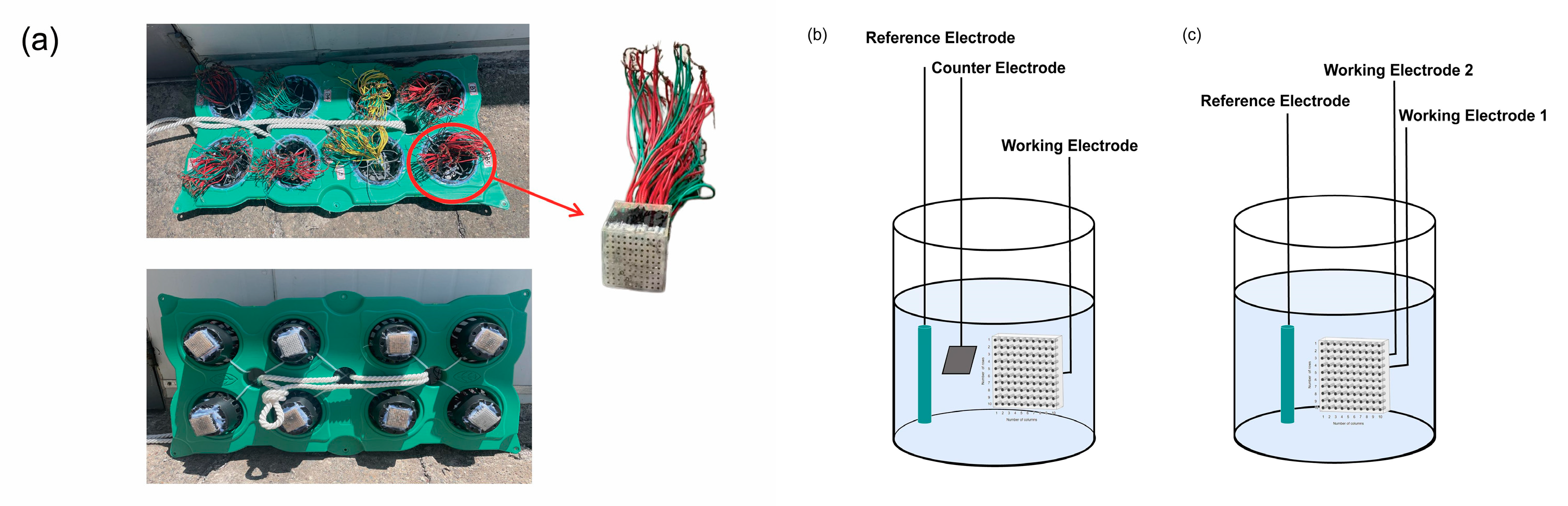
To obtain specimens covered with barnacles, the specimens were placed on a floating plate to ensure that the electrode working surface could be fully immersed in the seawater immersion area, as shown in Figure 1a. The distance was set at 10 cm to avoid hindering the free flow of seawater between electrodes.
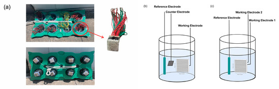
Figure 1.
(a) Float plate and specimen diagram; (b) three-electrode test system with potentiodynamic polarization and impedance diagram; (c) galvanic currents and potentials test system.
2.3. Electrochemical Characterization
The electrochemical tests, including electrochemical impedance spectroscopy, potentiodynamic polarization, and electrochemical noise, were carried out with a Wuhan CS350 electrochemical workstation. The test area of the microelectrode was 3.14 mm2. Five microelectrodes were selected for electrochemical impedance spectroscopy (EIS) and potentiodynamic polarization curve tests, corresponding to microelectrodes forming an initial biofilm at 7 days, forming a mature biofilm at 15 days, covered by living barnacles at 30 days, covered by recently dead barnacles, and covered by empty-shell barnacles that had been dead for some time at 90 days. The EIS test was carried out under an OCP, and the amplitude of the AC excitation signal was 10 mV in the frequency range of 105~10−2 Hz. Then, the acquired EIS data were fitted with an equivalent circuit using Zview 2.7 software. There are two types of polarization curve tests: three electrodes immersed for 30 days were scanned at a rate of 0.5 mV/s in the range of −200 mV to +200 mV (vs. OCP); two electrodes immersed for 90 days were scanned at a rate of 1 mV/s in the range of −300 mV to +300 mV (vs. OCP). Figure 1b shows a schematic of the electrochemical test equipment, both using a three-electrode cell. The saturated calomel electrode was the reference electrode, the 2 × 2 cm platinum plate was the counter electrode, and a microelectrode from the regularly collected array electrode was the working electrode. The electrolyte was seawater that was collected directly from the field.
Galvanic corrosion currents and potentials were corroded using electrochemical noise techniques to obtain the effects and patterns of biofouling on each microelectrode in the arrayed electrodes over time. Electrochemical noise was measured at a frequency of 10 Hz. The module measured the dynamic current and potential transfer characteristics between a single electrode and 99 other microelectrodes. The single electrode was working electrode 1 (W1), the other 99 electrodes were working electrode 2 (W2), and the saturated calomel electrode was the reference electrode (Figure 1c).
3. Results and Discussion
3.1. Electrochemical Distribution Pattern of Array Electrodes Affected by Fouling Organisms
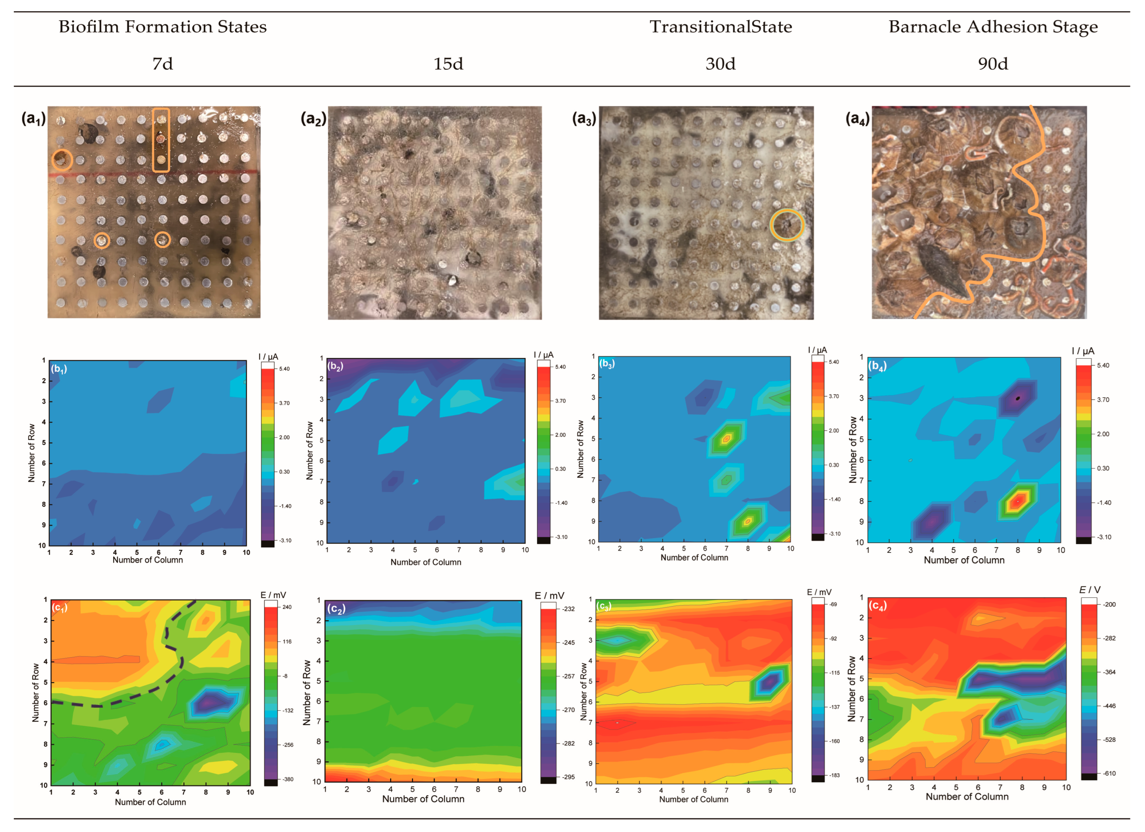
The surface image and the corresponding galvanic corrosion current and potential distributions of the specimens exposed for 7, 15, 30, and 90 days are shown in Figure 2.

Figure 2.
Surface photographs and electrochemical noise test results of electrodes immersed in seawater for 7, 15, 30, and 90 days: (a1–a4) surface photos immediately after retrieval; (b1–b4) galvanic potential distribution; (c1–c4) galvanic current distribution.
Figure 2a shows that the surface of the stainless steel array electrode immersed for 7 days had an initial biofilm that was very thin and sparse. There was little current, the potential was not uniformly distributed. Some microelectrodes were severely corroded, corresponding to the area of the yellow circle in Figure 2(a1). Over time, metabolites and corrosion products accumulate to form a mature and stable biofilm [23]. Therefore, the electrode immersed for 15 days and forming a visible slimy film had a more uniform distribution of both galvanic current and potential.
The presence of both biofilm and a small barnacle on the surface of the electrode that was immersed for 30 days could be considered as a transitional state. We found little change in the current in general, but the anode current peaked in the area around the barnacle. The potential shifted positively, and the difference grew. Since the potential of the area covered by the barnacle was lower than that of the area covered by the biofilm, we concluded that the barnacles prevented oxygen from reaching the surface of the substrate directly and formed an oxygen concentration battery with the surrounding environment that was susceptible to local corrosion [24].
After soaking for 90 days, 70% of the electrode surface was covered by macroscopic fouling organisms, which were mainly barnacles. The current and potential distribution characteristics were in good agreement with the surface image. The current in the uncovered area was negative as a cathode area, and that covered by macrofouling organisms was positive as an anode area. In addition, the potential was obviously shifted in a negative direction, and the range of fluctuation increased: the covered area was positive, while the other areas were negative. The potential of the area covered by dead barnacles was slightly lower than that of the area covered by living barnacles.
3.2. Corrosion Characteristics of Microelectrodes at Different Barnacle Growth Stages
During the growth stages, the barnacle passes through planktonic, naupliar, and nonfeeding cypris stages before metamorphosing into a larval barnacle [25]. The adult barnacle periodically secretes barnacle cement to secure its underwater attachment during growth [16]. The continued formation of new active cement glands at the periphery causes the base plate to continue to enlarge horizontally [26]. To better express the corrosion effects of different growth stages of barnacles on metal, three microelectrodes covered by living barnacles, recently dead barnacles, and empty-shell barnacles that were dead for some time were selected to represent the adult barnacle growth stages. Since biofilms are important for the attachment of macrofouling organisms, two specimens immersed in seawater for 7 days and 15 days were selected for this experiment to express early and mature stages of biofilm formation, respectively. Potentiodynamic polarization was carried out on the five microelectrodes (Figure 3b). The corrosion current densities (Icorr) and the corrosion potentials (Ecorr) obtained by Tafel fitting of the curves are shown in Table 2.
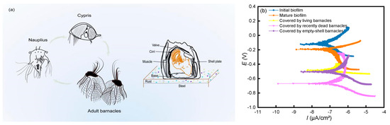
Figure 3.
(a) Schematic diagram of the barnacle growth process; (b) potentiodynamic polarization curves at different growing stages.
Table 2.
Results obtained from Tafel fitting.
Comparison of the fitting results between the initial and mature stages showed that the initial biofilm had a large Icorr and a fast corrosion rate. It was thinner and less protective. Because the local intensities of bacterial respiration may also differ in non-uniform biofilms, it is easy to form oxygen concentration cells and cause the local corrosion [27]. As the exposure time increased, a ribbon-like film appeared on the surface of the electrode immersed for 15 days, covering the microelectrodes. Mature biofilm had low Icorr and corrosion rate. Biofilm reaching a certain thickness could reduce the amount of oxygen reaching the stainless steel media surface, thus slowing down stainless steel corrosion.
The physical state of the steel corrosion interface was altered by the close contact between barnacles and the metal matrix. The barrier effect of the barnacle bottom shell impeded the transport of Cl− and dissolved oxygen, resulting in low Icorr and low corrosion rate values. The Ecorr values of microelectrode covered by living barnacles decreased by almost 300 mv compared to mature biofilm, but the Icorr values were close. This is because the barnacles attached to the metal were able to impede the transport of Cl− and dissolved oxygen. In seawater environments, oxygen transport is the controlling step in the corrosion rate of metals. Due to the barrier effect of the barnacle shell, the concentration of oxygen able to reach the metal surface is reduced, resulting in the diffusion rate of oxygen being affected. As a result, the amplitude of the Icorr increase was reduced, and the corrosion rate was low. In addition, the metabolites produced by feeding, metabolism, and other activities of barnacles can also affect metal corrosion [18].
However, once the barnacles died, Ecorr began to shift negatively. This phenomenon occurred because a high concentration of bacteria was attracted to the decomposing barnacle body. The bacteria not only consumed the oxygen in the cavity, but also decomposed the barnacle flesh into acidic products, causing the pH of the area to drop [28]. When decomposition was complete, the corrosion of the empty-shell barnacle stage was mitigated, and the Ecorr value increased. However, the metal was re-exposed to seawater and was in direct contact with reactive ions. This phenomenon increased Icorr to a value that was almost twice as much as that of the microelectrode covered by living barnacles.
Figure 4a,b shows the Bode and Nyquist plots of the specimens in the biofilm formation stage and adult barnacle growth stage.
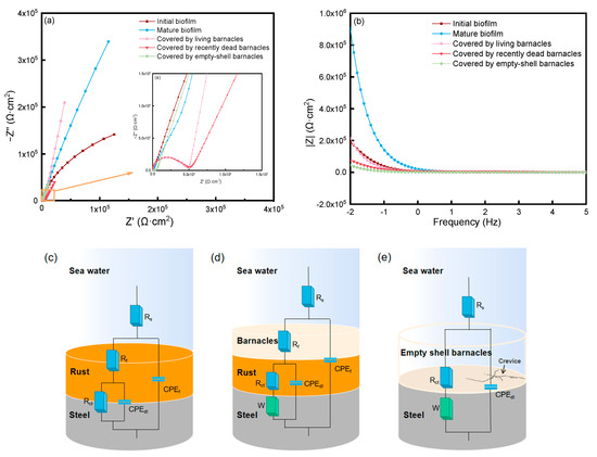
Figure 4.
(a,b) Electrochemical impedance spectrogram of barnacles at different growing stages and corresponding equivalent circuits: (c) biofilm; (d) living and recently dead barnacles; (e) empty-shell barnacles.
According to the Bode diagram, when the frequency was 0.01 Hz, the barrier ability was in the following order: mature biofilm > covered by living barnacles > initial biofilm > covered by recently dead barnacles > covered by empty-shell barnacles. The value of the biofilm increased with increasing immersion time from the initial stage to the mature stage, and the impedance value of the biofilm at the mature stage was the greatest (Z = 905,000 Ω·cm2), even greater than that of the microelectrode covered by living barnacles (Z = 213,000 Ω·cm2). Therefore, this stage had the best corrosion resistance. Moreover, the impedance values of living and recently dead barnacles exceeded those of empty-shell barnacles. The dense structures of the calcareous shell and barnacle glue contributed to the protection of metals from corrosion. The structures effectively prevented the entry and exit of ions and reduced the exchange of materials between metals and the outside world [29], weakening the corrosion. When barnacles decomposed, leaving an open empty shell, the barrier was destroyed, and the metal was open or semiopen, exacerbating corrosion.
The impedance spectrum was fitted using Zview 2.7 (error < 10%), as shown in Table 3. Figure 4c–e show the corresponding equivalent circuits. Figure 4c corresponds to the microelectrodes at the 7 and 15 days biofilm formation stages. The surface was not covered by macrofouling organisms, which formed too few corrosion products and biofilm to be directly observed, so the ‘Rust’ layer is used to represent the microfouling layer. Figure 4d corresponds to the electrodes covered by living and recently dead barnacles, which had an intact and confined structure. Since microorganisms create the microfouling layer which provides the proper settle sites and conditions for barnacle, the “Barnacle” layer is on top of the “Rust” layer [23]. In contrast, if the barnacle base plate was completely disintegrated, the re-accumulation of corrosion products or disintegration residues was negligible. Therefore, from a macroscopic point of view, the electrodes covered by empty-shell barnacles are shown in Figure 4e. Rs, Rf, and Rct represent the solution resistance, the pore or rust layer resistance between barnacle/steel and the charge transfer resistance, respectively. CPEf and CPEdl represent the barnacle/steel or rust layer capacitance and the double layer capacitance, respectively. The Warburg impedance (W) represents the corrosion reaction controlled by the diffusion of electrolyte across the barnacle/steel interface. Rp (Rp = Rf + Rct) usually represents the compactness of the corrosion product film, and it is negatively correlated with the metal corrosion rate [30].
Table 3.
Impedance curve fitting result.
From the fitting results, because the passivation film was in an unstable stage at the beginning of immersion, Rf and Rct were smaller than those in the mature biofilm. Anodic dissolution was hindered by the increased thickness of the mature biofilm, which significantly increased Rf and Rct, especially Rf, which increased by nearly ten times, causing the corrosion rate to decrease and the metals to be protected. This phenomenon further showed that the corrosion rate of the stainless steel electrode was fast in the initial stage of immersion in natural seawater; however, with the thickening of the film, the diffusion of Cl− and oxygen in the solution was hindered, the products of microbial metabolism were adsorbed on the surface, and the oxygen concentration reaching the surface was reduced. These phenomena changed the electrochemical conditions at the metal/solution interface, causing the induction or acceleration of corrosion to become corrosion inhibition [31]. This finding was consistent with the pattern of results from the potentiodynamic polarization analysis, as the dense biofilm provided improved protection for the metals.
The recently dead barnacles were affected by microorganisms, but overall, the barnacle bottom shell structure was more intact on the surface of both microelectrodes. Therefore, the Rp value of the living barnacles microelectrode was 2406.7 Ω·cm2, which was close to that of the recently dead barnacles. The Rp of the recently dead barnacles was slightly higher, presumably because the microelectrode of the recently dead barnacles was selected from the specimen of immersion for 90 days, when the diameter of the barnacle shells was larger, and the ability to adhere to the substrate was stronger. The main component of the barnacle bottom shell is calcite, which has poor conductivity. Thus, the effective area in the electrochemical reaction process was reduced, and the corrosion rate in the area covered by the intact shell was low. In contrast, the Rp of the microelectrode covered by the empty-shell barnacles was only 322 Ω·cm2, and the mid-to-high frequency region of the Nyquist diagram is significantly reduced. Because the existence of a residual shell made it difficult for the corrosion products to accumulate, the product film was insufficiently dense. As a result, the empty-shell barnacles had the most severe effect on metal corrosion.
In addition, previous research showed that the corrosion products of the steel had a high content of Fe3O4. The composition of the inner rust layer was basically the same as that of the outer layer, except for the absence of -FeOOH. It is therefore concluded that the composition of the rust layer is basically the same regardless of whether the barnacle adhered [29]. Crevice corrosion is more easily found under barnacles. It mostly occurs in the area covered by the shells of dead barnacles, which produces crack depths much greater than the area covered by living barnacles [20,32]. The structure of the base plate is a concentric ring pattern consisting of calcite bricks and cement duct [16]. We inferred that corrosion was present throughout the barnacle attachment process and that cracking was more likely to occur at the edge of the barnacle substrate. Among these stages, the empty-shell barnacle stage had the most severe corrosion effect on metal. As the barnacle wall plate and substrate were not firmly attached to each other. The barnacles used special muscles to support the wall plate, and the channel around the bottom shell secreted glue to completely fill the surface contours and fissures of both the baseplate and the substrate. Once solidified, this filling could provide a rigid mechanical bond to the surfaces [33] and make the structure of the corrosion product increasingly compact, thereby increasing the barrier to ion diffusion [34]. The CPE-T values of structurally intact barnacles were nearly an order of magnitude smaller than those of empty shells. CPE-T related to ion diffusion verified the protective effect of barnacles on the metal matrix. Therefore, the death of barnacles would attract a large number of bacteria, causing a series of negative effects on the metal. Saprophytic bacteria broke the original closed structure, which decomposed the barnacle’s body, lime crust and glue, resulting in a large influx of corrosive factors. After gathering in the “Rust” layer, Cl− slowly penetrated into the cracks of the substrate; the metabolites produced by the putrefactive bacteria in the decomposition process remained on the metal surface, affecting the corrosion process of the metal. The combined action of the two could help initiate the corrosion process. Thus, the empty barnacle shell has the largest value of CPE-T and the smallest value of W-R, which is only 748 Ω−1cm−2S0.5. This result showed that this stage was likely to experience ion diffusion and that the corrosion rate was high. The cracks under the bottom shells of barnacles were in the process of development and expansion, which exacerbated the crevice corrosion of the metal.
4. Conclusions
In this study, morphological and electrochemical tests were used to investigate the effects of different growth stages of barnacles, from biofilm formation to complete disintegration of the barnacle shell, on the corrosion behavior of 304 stainless steel.
- The severity of corrosion in 304SS decreases and subsequently increases with increasing immersion time due to the influences of marine fouling organisms. The inhibition of corrosion in metals is most effective during the mature biofilm stage, whereas corrosion is most severe during the empty shell stage.
- The results of the biofilm formation stages show that the galvanic current and potential distributions of the initial biofilm are uneven. With the prolongation of immersion time, both the thickness and uniformity of the biofilm increase. Mature biofilms have a certain inhibitory effect on corrosion, allowing the corrosion rate to be reduced.
- The different growth stages of barnacles have different corrosion mechanisms on 304SS: structurally intact barnacles protect metals well. The dense structure of the calcareous shell and glue can effectively limit the transmission of external corrosive factors. Although the metal covered by recently dead barnacles is affected by the decomposition of corrosive bacteria, the overall structure is still intact, as is that covered by living barnacles. The shell plays a role in limiting the transfer of external substances to some extent, reducing the concentration of oxygen reaching the metal surface and affecting the diffusion rate of oxygen.
- The galvanic current and potential distribution roughly match the bioattachment site. Barnacle attachment behavior has some corrosive effect on the metal in the surrounding area.
Author Contributions
Conceptualization, P.D.; methodology, P.D.; validation, P.D., J.S. and B.G.; formal analysis, P.D. and J.S.; investigation, J.S. and P.W.; resources, P.D. and J.H.; data curation, J.S.; writing—original draft preparation, P.D. and J.S.; writing—review and editing, P.D., J.S., J.H. and P.W.; supervision, J.H.; project administration, P.D., B.G. and J.H.; funding acquisition, P.D. and J.H. All authors have read and agreed to the published version of the manuscript.
Funding
This research was funded by Natural Science Foundation of Guangdong Province (No. 2021A1515012129) and the Science & Technology Development Foundation of Zhanjiang (No. 2022A01029).
Data Availability Statement
Not applicable.
Acknowledgments
The authors are sincerely grateful for the financial support from the Natural Science Foundation of Guangdong Province (No. 2021A1515012129) and the Science & Technology Development Foundation of Zhanjiang (No. 2022A01029).
Conflicts of Interest
The authors declare no conflict of interest.
References
- Hunt, J.D.; Zakeri, B.; de Barros, A.G.; Filho, W.L.; Marques, A.D. Buoyancy Energy Storage Technology: An energy storage solution for islands, coastal regions, offshore wind power and hydrogen compression. J. Energy Storage 2021, 40, 102746. [Google Scholar] [CrossRef]
- Barooni, M.; Ashuri, T.; Sogut, D.V.; Wood, S. Floating Offshore Wind Turbines: Current Status and Future Prospects. Energies 2023, 16, 2. [Google Scholar] [CrossRef]
- Adedipe, O.; Brennan, F.; Kolios, A. Review of corrosion fatigue in offshore structures: Present status and challenges in the offshore wind sector. Renew. Sustain. Energy Rev. 2016, 61, 141–154. [Google Scholar] [CrossRef]
- Kirchgeorg, T.; Weinberg, I.; Hornig, M.; Baier, R.; Schmid, M.J. Emissions from corrosion protection systems of offshore wind farms: Evaluation of the potential impact on the marine environment. Mar. Pollut. Bull. 2018, 136, 257–268. [Google Scholar] [CrossRef]
- Wang, Z.; Wang, X.; Huang, Y.; Zhou, H.; Wu, Y. Macrofouling organisms: Protection or damage of steel in marine environments? Corros. Sci. 2023, 212, 110928. [Google Scholar] [CrossRef]
- Védie, E.; Brisset, H.; Briand, J.F.; Bressy, C. Bioinspiration and microtopography as nontoxic strategies for marine bioadhesion control. Adv. Mater. Interfaces 2021, 8, 2100994. [Google Scholar] [CrossRef]
- Delgado, A.; Power, S.; Richards, C.; Daly, P.; BriciuBurghina, C. Establishment of an antifouling performance index derived from the assessment of biofouling on typical marine sensor materials. Sci. Total Environ. 2023, 887, 164059. [Google Scholar] [CrossRef]
- Relini, G.; Tixi, F.; Relini, M.; Torchia, G. The macrofouling on offshore platforms at Ravenna. Int. Biodeterior. Biodegrad. 1998, 41, 41–55. [Google Scholar] [CrossRef]
- Al-Muhanna, K.; Habib, K. Corrosion behavior of different alloys exposed to continuous flowing seawater by electrochemical impedance spectroscopy (EIS). Desalination 2010, 250, 404–407. [Google Scholar] [CrossRef]
- Noor, N.M.; Yahaya, N.; Abdullah, A. Microbiologically influenced corrosion of X-70 carbon steel by desulfovibrio vulgaris. Adv. Sci. Lett. 2012, 13, 312–316. [Google Scholar] [CrossRef]
- Zulkafli, R.; Othman, N.K.; Yaakob, N. Localised corrosion of API 5L X65 carbon steel in marine environments: The role of sulfate-reducing bacteria (SRB). J. Bio-Tribo-Corros. 2022, 9, 12. [Google Scholar] [CrossRef]
- Liu, W. Rapid MIC attack on 2205 duplex stainless steel pipe in a yacht. Eng. Fail. Anal. 2014, 42, 109–120. [Google Scholar] [CrossRef]
- Antony, P.J.; Chongdar, S.; Kumar, P.; Raman, R. Corrosion of 2205 duplex stainless steel in chloride medium containing sulfate-reducing bacteria. Electrochim. Acta. 2007, 52, 3985–3994. [Google Scholar] [CrossRef]
- Xu, D.; Xia, J.; Zhou, E.; Zhang, D.; Zhang, D.; Yang, C.; Li, Q.; Lin, H.; Li, X.; Yang, K. Accelerated corrosion of 2205 duplex stainless steel caused by marine aerobic Pseudomonas.aeruginosa biofilm. Bioelectrochemistry 2017, 113, 1–8. [Google Scholar] [CrossRef]
- Huang, L.; Chang, W.; Zhang, D.; Huang, Y.; Li, Z. Acceleration of corrosion of 304 stainless steel by outward extracellular electron transfer of Pseudomonas aeruginosa biofilm. Corros. Sci. 2022, 199, 110159. [Google Scholar] [CrossRef]
- Palanichamy, S.; Subramanian, G. Hard foulers induced crevice corrosion of HSLA Steel in the Coastal Waters of the Gulf of Mannar (Bay of Bengal). J. Mar. Sci. Appl. 2014, 13, 117–126. [Google Scholar] [CrossRef]
- Wang, Z.; Huang, Y.; Wang, X.; Xu, Y.; Cai, F. Effects of oyster as macrofouling organism on corrosion mechanisms of a high-strength low-alloy steel. Corros. Sci. 2022, 207, 110580. [Google Scholar] [CrossRef]
- Neville, A.; Hodgkiess, T. Localised effects of macrofouling species on electrochemical corrosion of corrosion resistant alloys. Br. Corros. J. 2000, 35, 54–59. [Google Scholar] [CrossRef]
- Sangeetha, R.; Kumar, R.; Venkatesan, R.; Doble, M.; Vedaprakash, L.; Lakshmi, K. Understanding the structure of the adhesive plaque of Amphibalanus reticulatus. Mater. Sci. Eng. 2010, 30, 112–119. [Google Scholar] [CrossRef]
- Blackwood, D.J.; Lim, C.S.; Teo, S.L.M.; Hu, X.; Pang, J. Macrofouling induced localized corrosion of stainless steel in Singapore seawater. Corros. Sci. 2017, 129, 152–160. [Google Scholar] [CrossRef]
- Patel, B.; Crisp, D. The influence of temperature on the breeding and the moulting activities of some warm-water species of operculate barnacles. J. Mar. Biol. Assoc. UK 1960, 39, 667–680. [Google Scholar] [CrossRef]
- Chen, X.; Liu, Q.; Zhuo, W.; Liu, W.; Li, Z.; Tang, M. The characteristic patterns of macrofaunal fouling assemblages in nearshore waters of the South China Sea. J. Ocean. Univ. China 2018, 17, 1142–1148. [Google Scholar] [CrossRef]
- Li, Y.; Ning, C. Latest research progress of marine microbiological corrosion and bio-fouling, and new approaches of marine anti-corrosion and anti-fouling. Bioact. Mater. 2019, 4, 189–195. [Google Scholar] [CrossRef]
- Hu, J.; Shangguan, J.; Deng, P.; Feng, Q.; Wang, G.; Wang, P. Effect of barnacle adhesion on corrosion behavior of Q235 steel. J. Chin. Soc. Corros. Prot. 2023, 43, 1145–1150. [Google Scholar]
- Venkatnarayanan, S.; Murthy, P.S.; Kirubagaran, R.; Venugopalan, V.P. Effect of chlorination on barnacle larval stages: Implications for biofouling control and environmental impact. Int. Biodeterior. Biodegrad. 2016, 109, 141–149. [Google Scholar] [CrossRef]
- Liang, C.; Strickland, J.; Ye, Z.; Wu, W.; Hu, B.; Rittschof, D. Biochemistry of barnacle adhesion: An updated review. Front. Mar. Sci. 2019, 6, 565. [Google Scholar] [CrossRef]
- Lou, Y.; Chang, W.; Cui, T.; Wang, J.; Qian, H.; Ma, L.; Hao, X.; Zhang, D. Microbiologically influenced corrosion inhibition mechanisms in corrosion protection: A review. Bioelectrochemistry 2021, 141, 107883. [Google Scholar] [CrossRef]
- Eashwar, M.; Subramanian, G.; Chandrasekaran, P.; Balakrishnan, K. Mechanism for barnacle-induced crevice corrosion in stainless steel. Corros. Sci. 1992, 48, 608–612. [Google Scholar] [CrossRef]
- Cai, F.; Huang, Y.; Xing, S.; Xu, Y.; Zhao, X. Characteristics and mechanisms of low-alloy high-strength steel corrosion behavior under barnacle adhesion based on a comparison experiment. Corros. Sci. 2023, 217, 111146. [Google Scholar] [CrossRef]
- Sun, H.; Wang, Z.; Gao, P.; Liu, P. Selection of aquatic plants for phytoremediation of heavy metal in electroplate wastewater. Acta Physiol. Plant. 2012, 35, 355–364. [Google Scholar] [CrossRef]
- Gao, Y.; Feng, D.; Moradi, M.; Yang, C.; Jin, Y. Inhibiting corrosion of aluminum alloy 5083 through Vibrio species biofilm. Corros. Sci. 2021, 180, 109188. [Google Scholar] [CrossRef]
- Xu, Y.; Huang, Y.; Cai, F.; Lu, D.; Wang, X. Study on corrosion behavior and mechanism of AISI 4135 steel in marine environments based on field exposure experiment. Sci. Total Environ. 2022, 830, 154864. [Google Scholar] [CrossRef] [PubMed]
- Raman, S.; Karunamoorthy, L.; Doble, M.; Kumar, R.; Venkatesan, R. Barnacle adhesion on natural and synthetic substrates: Adhesive structure and composition. Int. J. Adhes. Adhes. 2013, 41, 140–143. [Google Scholar] [CrossRef]
- Sangeetha, R.; Kumar, R.; Doble, M.; Venkatesan, R. Barnacle cement: An etchant for stainless steel 316L? Colloids Surf. B Biointerfaces 2010, 79, 524–530. [Google Scholar] [CrossRef] [PubMed]


Disclaimer/Publisher’s Note: The statements, opinions and data contained in all publications are solely those of the individual author(s) and contributor(s) and not of MDPI and/or the editor(s). MDPI and/or the editor(s) disclaim responsibility for any injury to people or property resulting from any ideas, methods, instructions or products referred to in the content. |
© 2023 by the authors. Licensee MDPI, Basel, Switzerland. This article is an open access article distributed under the terms and conditions of the Creative Commons Attribution (CC BY) license (https://creativecommons.org/licenses/by/4.0/).