Abstract
In this paper, the giant magneto-impedance (GMI) model of a cylindrical alloy fiber was established by the Maxwell equation and Landau–Lifshitz equation to simulate the influence of physical parameters of cylindrical alloy fiber on GMI under different control parameters. MATLAB was employed to calculate the magneto-impedance of cylindrical fibers and draw its curves. We found that when the anisotropic equivalent field of the fiber changes from 10Oe to 50Oe, the peak position of the GMI ratio also moves from about 10Oe to 50Oe, and the peak value gradually increases from 100% to 300%. The GMI ratio increased rapidly with the decrease in the magnetization damping coefficient. Our findings could further guide the design of supersensitive micro GMI sensors by optimally regulating the magnetic damping coefficient, the angle between the external magnetic field and easy axis and the anisotropic equivalent field of cylindrical alloy fibers.
1. Introduction
GMI effect is the large variation of the impedance of soft magnetic materials carrying an alternating current in the presence of an external magnetic field. In some special structural ferrimagnetic materials, such as cylindrical alloy fibers, the field sensitivity reaches a high level of 1200%/Oe [1]. This cylindrical structure shows great potential for development of a high-sensitive magnetic sensor owing to its great variations in circular permeability even by the use of a small external magnetic field. It is embedded into the composite material by a weaving process, which is used to monitor the local damage judgment and location in the composite material [2]. In addition, cylindrical alloy fibers with different magnetic properties can be obtained by adjusting the preparation process parameters, making them suitable for different application scenarios [3,4,5,6,7].
There are several theoretical models with respect to GMI effect in cylindrical micro-fiber, including the quasi-static model, eddy current model, magnetic domain model, etc. When the frequency of an alternating current is higher than 1MHz, the skin effect is obvious, and its contribution to transverse or annular permeability must be considered. A giant magneto-impedance eddy current model is used to calculate the circumferential permeability of a cylindrical metal wire, which can explain GMI effect of medium and high frequency, and has been widely used [8].
Recently, a series of papers reported the preparation of metal fibers with different compositions and the measurement and theoretical analysis of GMI effect [9,10,11]. The effects of different temperatures, magnetic field environments, different stress states and different heat treatment methods on GMI effect in cylindrical microfibers have been studied [12,13,14], but the effects of various physical parameters of cylindrical alloy fibers on GMI effect have not been systematically studied. In this paper, a GMI model of a cylindrical microfiber is presented, and the influence of the magnetic damping coefficient, the angle between the external magnetic field and easy axis and the anisotropic equivalent field on magnetic impedance is analyzed under different control parameters, which provides useful information for the optimal design of ultra-sensitive GMI sensors.
2. GMI Model of Cylindrical Microfiber
The giant magneto-impedance (GMI) effect means that when a high-frequency alternating current is applied to a soft magnetic conductive material, the AC impedance at both ends of the material will change significantly with the change in the axial-applied magnetic field. Figure 1a is a schematic diagram of a common measuring circuit for GMI effect of cylindrical microfibers. U represents the AC voltage source, R represents the standard resistance for detecting driving current, Iac represents the driving alternating current, Uac represents AC voltage across the sample, and He represents the applied magnetic field [15]. Generally, the domain structure of Fe-Co-based amorphous wire is that the inner core has axially distributed magnetic domains, and the outer core has circumferentially distributed magnetic domains, alternating left and right [8], as shown in Figure 1b. In the calculation, the magnetic domain in the cylindrical alloy fiber is assumed to be an ellipsoidal magnetic domain with the alternating magnetization of 180 degrees. When the fiber is supplied with a high-frequency alternating current, the magnetic domain precesses. The magnetization of a single magnetic domain is calculated and then applied to the fiber. Figure 1c shows the reference coordinate system, with the direction of current passing (the axial direction of the fiber) as the X axis, the radial direction of the fiber in the vertical plane as the Y axis, and the direction perpendicular to the XY plane as the Z axis. The n is the easy axis direction of the assumed ellipsoidal magnetic domain, M0 is the static magnetization of the magnetic domain, and its angle with the easy axis direction is θ. The Hα is the anisotropic equivalent field, which consists of a magnetic anisotropy field and magnetoelastic stress field. The angle between Hα and M0 is θk, and the angle between the anisotropic field and X-axis direction is θα.

Figure 1.
(a) The schematic diagram of GMI effect in cylindrical alloy fiber. (b) Schematic diagram of the magnetic domain structure. (c) Coordinates of cylindrical alloy fiber.
GMI effect is closely related to the driving current frequency. The magnetic induction effect observed at low frequency is not obvious and nonlinear, so it is not suitable to be used as the driving current frequency of the GMI sensor. In the range of intermediate frequency, the change in the external magnetic field leads to great changes in the effective permeability and skin depth of the material, resulting in an obvious change in the real part R and imaginary part X of the magnetic impedance (Z = R + jX). In the high-frequency range, the domain wall movement in the magnetization process is completely inhibited by the eddy current effect, and the influence of magnetic moment-rotation on GMI effect is dominant. Dynamics becomes an important factor, so the model based on Maxwell equations and Landau–Lifshitz equations is more accurate.
According to the domain wall motion equation and the Landau–Lifshitz magnetic moment-rotation equation, the low-frequency domain wall motion permeability and high-frequency magnetic moment-rotation permeability of the material driven by alternating the current can be obtained by the magnetic moment direction inside the material and the physical parameters of the material, such as conductivity, initial magnetic susceptibility, anisotropic field, gyromagnetic ratio and damping coefficient. Then the impedance expression of the material is obtained by Maxwell equations.
When an alternating current I = Ime (−jwt) acts on the ferromagnetic microfiber with a length l and uniform magnetization, the induced magnetic field around the wire is: H = I/2 πd, where d is the radius of the conductor. The alternating induced magnetic field causes a change in the circumferential magnetic flux and produces alternating induced electromotive force at both ends of the conductor:
where ϕ and B are the magnetic flux and magnetic induction intensity through the wire, respectively. dB/dH is the component of the transverse differential permeability of the wire along the circumferential direction.
When an external magnetic field is applied in the longitudinal direction of the wire, the circumferential permeability of the wire changes; thus, the self-inductance coefficient and induced electromotive force of the wire change. Because of the complex magnetic domain structure and uneven magnetization of ferromagnetic amorphous wire materials, the skin effect will be obvious when the frequency is high. The impedance of the material should be calculated according to Maxwell’s equation. When alternating current is applied to the amorphous wire, the transverse electric field and magnetic field distribution can be obtained as follows:
where J0 and J1 are the zero-order and first-order Bessel functions of the first kind, respectively, σ is the conductivity of the material, c is the speed of light and k is the radial propagation constant, and its value can be given as:
where i is the imaginary unit, is the skin depth of the sample, and μφ is the permeability of the sample.
At high frequencies, the domain wall motion of the material is completely suppressed, and only the magnetization vector precession mechanism exists. The free energy inside the fiber is mainly composed of magnetostatic energy, magnetic isotropic energy and magnetoelastic energy, which is expressed as:
where Ms is the saturation magnetization, K is the isotropic point temperature, λ is the constant of sample material measurement, and σ is the stress. In the equilibrium state, the inside of the sample should be in the state of minimum free energy, which is expressed as:
The permeability is calculated by solving the precession equation of magnetization. The effective permeability expression of cylindrical metal fiber can be obtained by jointly solving Maxwell’s equation and the magnetization precession equation with the Gilbert damping term. The calculation results are as follows:
where μeff is the effective permeability, γ is the gyromagnetic ratio, MS is the saturation magnetization and α is the damping coefficient.
Ignore the electromagnetic field energy outside the sample and consider the internal energy consumption. The following equation can be obtained from the law of conservation of energy:
The impedance of the available material is:
It can be seen from the impedance expression that the impedance value of ferromagnetic materials depends on the skin depth of the materials, which in turn depends on the circumferential or transverse permeability.
3. Results and Discussion
The physical parameters of cylindrical alloy fiber are brought into the GMI model calculation formula of cylindrical alloy fiber for MATLAB simulation, and the impedance change and GMI effect change under different conditions are obtained. In order to compare GMI effect under different conditions, the GMI ratio is used to represent GMI effect [16]:
where Z(He) represents the impedance value of the GMI material under the action of an external magnetic field, and Z(Hsat) is the reference value of GMI effect, which is the impedance value when magnetization is saturated.
The basic parameters of cylindrical alloy fiber selected in the calculation are as follows: the length is 5 mm, the diameter is 160 μm, the electric conductivity is 106 S/m, the saturation magnetic field intensity is 200Oe, the magnetic anisotropic equivalent field is 20Oe, the damping coefficient is 0.3, and the angle between the easy axis direction and the applied magnetic field direction is 80 degrees. The influence of its parameters on GMI effect is calculated on the basis of changing the corresponding parameters.
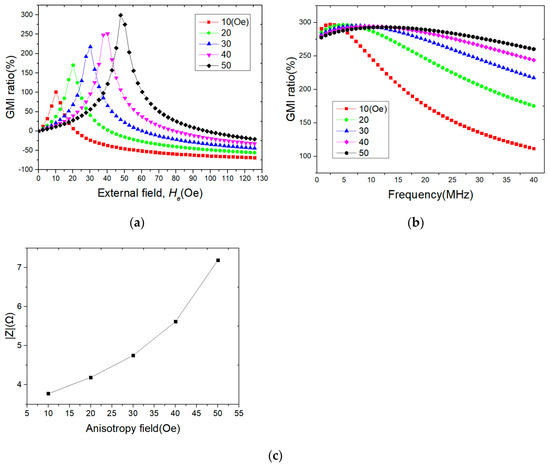
Figure 2 shows GMI effect curve of cylindrical alloy fiber under the applied magnetic field with different anisotropic equivalent magnetic fields. As shown in Figure 2a, when the anisotropic equivalent field of the cylindrical alloy fiber changes from 10Oe to 50Oe, the peak position of GMI effect also moves from around 10Oe to 50Oe, and the peak value increases from 100% to 300% gradually. Usually, when the applied magnetic field direction is perpendicular to the easy magnetization direction of the sample, the GMI peak appears near the anisotropy equivalent field attachment. With the change in the anisotropic equivalent field, the permeability of the sample will change, which will affect the impedance of the material. It can be seen from Figure 2b that the variation curves of the GMI ratio with frequency are quite different under different anisotropic equivalent magnetic fields, and from Figure 2c, it can be seen that the impedance of cylindrical alloy fibers increases rapidly with the increase in anisotropic magnetic fields. The existence of an anisotropic equivalent field has a great influence on GMI effect, which not only determines the position of GMI effect peak but also determines the peak value. The increase in the GMI ratio peak value represents the improvement of its performance, and the increase in the single peak position indicates the decrease in GMI sensitivity with the change in the magnetic field, which is unfavorable to the application of the sensor. Maintaining the GMI ratio peak value as constant and applying a biased magnetic field can make the peak position close to the zero position and improve the sensitivity of the sensor [17].

Figure 2.
Effect of anisotropy field on GMI effect in cylindrical alloy fiber. (a) Curve of GMI effect with external field. (b) Curve of GMI effect with frequency. (c) Curve of impedance value with anisotropy field.
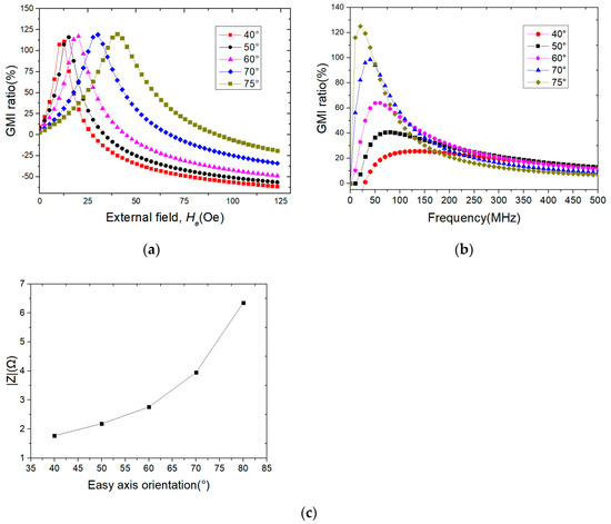
In order to study the influence of the easy magnetization direction of cylindrical alloy fiber on GMI effect, the change in GMI effect was simulated according to different angles between an easy magnetization axis direction and an applied magnetic field direction in cylindrical alloy fiber. Figure 3 is GMI effect curves of cylindrical alloy fiber with different easy axis orientations, among which Figure 3a shows GMI effect curves with different easy axis orientations under an external magnetic field. It can be seen that with the change in the easy axis angle, the peak value of GMI effect changes, and so does its appearance position. Figure 3b shows the curves of GMI effect with frequency under different easy axis orientations, and from Figure 3c, it can be that the impedance of cylindrical alloy fibers increases rapidly with the increase in the easy axis angle. It can be seen that with the increase in the easy axis angle, the peak value of the GMI ratio gradually increases. The direction of the easy axis has an obvious influence on the GMI ratio. In the preparation process of a sensor, a magnetic field can be applied to produce regular easy axis orientation, or a better easy axis orientation can be obtained by proper heat treatment to improve the sensor performance.

Figure 3.
Effect of easy axis orientation on GMI effect in cylindrical alloy fiber. (a) Curve of GMI effect with external field. (b) Curve of GMI effect with frequency. (c) Curve of impedance value with easy axis orientation.
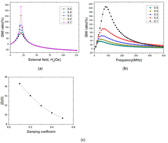
The magnetization of cylindrical alloy fiber will be damped in the precession process, and its GMI effect will also change. The magnetic damping coefficient is used to characterize the magnitude of resistance to magnetization. GMI effect of cylindrical alloy fibers with different damping coefficients was simulated. Figure 4 shows GMI effect curves of cylindrical alloy fibers with different damping coefficients, where Figure 4a is the curve of the GMI ratio with an external magnetic field under different damping coefficients. With the decrease in the damping coefficient, the peak value of the GMI ratio increases sharply. Figure 4b is the curve of the GMI ratio with frequency under different damping coefficients, and Figure 4c shows that its impedance decreases rapidly with an increase in the damping coefficient. It can be seen that with a decrease in the damping coefficient, the peak value of the GMI ratio increases gradually, and the peak position approaches a higher frequency. When selecting GMI sensor materials, magnetic materials with a low damping coefficient and suitable frequency should be selected to obtain better performance. In practice, many factors need to be considered in the damping coefficient of the material [18], such as ambient temperature, material uniformity, etc.

Figure 4.
Effect of damping coefficient on GMI effect in cylindrical alloy fiber. (a) Curve of GMI effect with external field. (b) Curve of GMI Effect with frequency. (c) Curve of impedance value with damping coefficient.
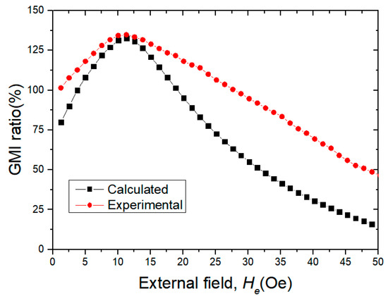
In Figure 5, the red curve is the GMI curve measured by Yangyong [19] at the frequency of 8 MHz. The metal fiber used is made of Co68Fe4.5Cr1Si13.5B14 by hot-melting and cold-drawing, and its diameter is 50 μm. The black curve is the curve simulated by adjusting various parameters. It can be seen that the calculated results are roughly consistent with the experimental results, and there are some subtle differences between them, which may be caused by oversimplification of the magnetic domain model or other factors in the sample preparation process.

Figure 5.
Experimental GMI values and calculated GMI data values.
4. Conclusions
The GMI model of cylindrical alloy fiber is established, and the effects of the magnetic damping coefficient, the angle between the external magnetic field and easy axis and the anisotropic equivalent field on GMI effect of cylindrical alloy fiber were simulated with MATLAB. The GMI ratio reaches its peak near the anisotropic equivalent field and increases with an increase in the anisotropic equivalent field; the GMI ratio increases with an increase in the angle between the external magnetic field and easy axis and decreases rapidly with an increase in the magnetization damping coefficient. The simulation results show that these three parameters have an obvious influence on GMI effect of cylindrical alloy fiber, and the design of ultra-sensitive micro GMI sensors can be further guided by optimizing relevant parameters.
Author Contributions
Writing—review and editing, model establishment, T.W.; writing—original draft, theoretical calculation, Y.Z.; funding, J.L.; formal analysis, Q.W.; visualization, J.C.; supervision, H.L.; software, Z.W.; resources, Z.C.; validation, M.L.; data curation, J.R. All authors have read and agreed to the published version of the manuscript.
Funding
This research was funded by the National Natural Science Foundation of China (Grant Nos. 51775323, 61991415, 52075315 and 51675321).
Institutional Review Board Statement
Not applicable.
Informed Consent Statement
Not applicable.
Data Availability Statement
The data that support the fundings of this study are available from the corresponding author, Lei, J., upon reasonable request.
Conflicts of Interest
The authors declare no conflict of interest.
References
- Garcia, D.; Raposo, V.; Montero, O.; Iniguez, J.I. Influence of magnetostriction constant on magnetoimpedance–frequency dependence. Sens. Actuators A Phys. 2006, 129, 227–230. [Google Scholar] [CrossRef]
- Qin, F.X.; Peng, H.X.; Popov, V.V.; Panina, L.V.; Ipatov, M.; Zhukova, V.; Zhukov, A.; Gonzalez, J. Stress tunable properties of ferromagnetic microwires and their multifunctional composites. J. Appl. Phys. 2011, 109, 07A310. [Google Scholar] [CrossRef]
- Liu, J.; Pang, M.; Cao, G.; Qu, G.; Wang, X.; Zhang, Y.; Liu, R.; Shen, H. Comparative study of tensile properties and magnetic properties for Nb-doped Fe-based wires. J. Mater. Res. Technol. 2020, 9, 12907–12916. [Google Scholar] [CrossRef]
- Namiki, A.; Yokosawa, S. Origami folding by multifingered hands with motion primitives. Cyborg Bionic Syst. 2021, 2021, 9851834. [Google Scholar] [CrossRef]
- Liu, J.; Qin, F.; Chen, D.; Shen, H.; Wang, H.; Xing, D.; Phan, M.-H.; Sun, J. Combined current-modulation annealing induced enhancement of giant magnetoimpedance effect of Co-rich amorphous microwires. J. Appl. Phys. 2014, 115, 17A326. [Google Scholar] [CrossRef]
- Jiang, S.; Wang, H.; Estevez, D.; Huang, Y.; Zhang, L.; Shen, H.; Ning, Z.; Qin, F.; Sun, J. Surface microstructural design to improve mechanical and giant magneto-impedance properties of melt-extracted CoFe-based amorphous wires. Mater. Des. 2021, 204, 109642. [Google Scholar]
- Wang, H.; Kan, J.; Zhang, X.; Gu, C.; Yang, Z. Pt/CNT micro-nanorobots driven by glucose catalytic decomposition. Cyborg Bionic Syst. 2021, 2021, 9876064. [Google Scholar] [CrossRef]
- Panina, L.; Mohri, K.; Uchiyama, T.; Noda, M.; Bushida, K. Giant magneto-impedance in Co-rich amorphous wires and films. IEEE Trans. Magn. 1995, 31, 1249–1260. [Google Scholar] [CrossRef]
- Velleuer, J.; Munoz, A.G.; Yakabchuk, H.; Schiefer, C.; Hackl, A.; Kisker, E. Giant magneto impedance in electroplated NiFeMo/Cu microwires. J. Magn. Magn. Mater. 2007, 311, 651–657. [Google Scholar] [CrossRef]
- Wang, H.; Qin, F.X.; Xing, D.W.; Cao, F.Y.; Wang, X.D.; Peng, H.X.; Sun, J.F. Relating residual stress and microstructure to mechanical and giant magneto-impedance properties in cold-drawn Co-based amorphous microwires. Acta Mater. 2012, 60, 5425–5436. [Google Scholar] [CrossRef]
- Ipatov, M.; Chizhik, A.; Zhukova, V.; Gonzalez, J.; Zhukov, A. Correlation of surface domain structure and magneto-impedance in amorphous microwires. J. Appl. Phys. 2011, 109, 113924. [Google Scholar] [CrossRef]
- Zhang, S.L.; Sun, J.F.; Xing, D.W.; Qin, F.X.; Peng, H.X. Large GMI effect in Co-rich amorphous wire by tensile stress. J. Magn. Magn. Mater. 2011, 323, 3018–3021. [Google Scholar] [CrossRef]
- Qin, F.; Peng, H.X. Ferromagnetic microwires enabled multifunctional composite materials. Prog. Mater. Sci. 2013, 58, 183–259. [Google Scholar] [CrossRef]
- Le, A.T.; Cho, W.S.; Lee, H.; Vázquez, M.; Kim, C.O. Giant magnetoimpedance effect in a glass-coated microwire LC-resonator for high-frequency sensitive magnetic sensor applications. J. Alloys Compd. 2007, 443, 32–36. [Google Scholar] [CrossRef]
- Phan, M.H.; Peng, H.X. Giant magnetoimpedance materials: Fundamentals and applications. Prog. Mater. Sci. 2008, 53, 323–420. [Google Scholar]
- Ma, L.; Zhao, C.; Ji, W.; Liu, Q.; Wang, J. Giant magneto-impedance effect adjusted by electrolytic polishing and thinning of Co-based amorphous ribbons. J. Phys. D Appl. Phys. 2022, 55, 34. [Google Scholar] [CrossRef]
- Zhukov, A.; Ipatov, M.; Corte-León, P.; Gonzalez-Legarreta, L.; Blanco, J.M.; Zhukova, V. Soft magnetic microwires for sensor applications. J. Magn. Magn. Mater. 2020, 498, 166180. [Google Scholar] [CrossRef]
- García, K.L.; Valenzuela, R. Correlation between magnetization processes and giant magnetoimpedance response in CoFeBSi amorphous CoFeBSi wires. J. Non-Cryst. Solids 2001, 287, 313–317. [Google Scholar] [CrossRef]
- Zhao, Y.; Hao, H.; Zhang, Y. Preparation and giant magneto-impedance behavior of Co-based amorphous wires. Intermetallics 2013, 42, 62–67. [Google Scholar] [CrossRef]
Publisher’s Note: MDPI stays neutral with regard to jurisdictional claims in published maps and institutional affiliations. |
© 2022 by the authors. Licensee MDPI, Basel, Switzerland. This article is an open access article distributed under the terms and conditions of the Creative Commons Attribution (CC BY) license (https://creativecommons.org/licenses/by/4.0/).