Abstract
Fabrication of a newly developed high entropy alloy is an essential step to enable it to be used as an industrial structure for its potential applications, such as billets, frames and tubes. Bulk forming processes at high temperatures are preferably used requiring the hot flow behavior of the HEA, which needs to be thoroughly investigated for accurate construction of a robust constitutive model and, hence, reliable process simulation and optimizations. In this study, to compensate for the lack of modelling microstructure using conventional phenomenological models, a novel physical mechanism-based model of CoCrFeMnNi high-entropy alloy was established. Particularly, the adiabatic heat effect was taken into account for modelling the HEA for the first time. The hot flow behavior, as well as grain evolution of this alloy under different forming conditions, are well modelled. The modelling predictions obtain great agreement with the experimental results, the calculated R-value (all higher than 0.95) and AARE (all smaller than 0.05) because the different conditions provide validity to the accuracy of the model prediction. In addition, the temperature increase due to deformation heat was well predicted to further evident to the accuracy of model. Furthermore, the hardening behavior during hot deformation was also compared, enabling the provision of useful guides for process designers of hot bulk forming HEAs.
1. Introduction
Traditional alloys such as aluminum and titanium alloys, those widely used in aerospace components, are unable to meet the stringent service requirements of new generation transport vehicles, especially for high temperature applications. Development of new high-entropy alloys has brought promising possibilities for researchers to design such alloys to obtain satisfying high temperature properties.
In 2004, Yeh et al. [1] firstly defined a new class of multi-component equiatomic alloy, which are commonly reerred to as HEAs (high-entropy alloys). Up to date, different kinds of HEAs with promising properties have been reported, including face-centered cubic (FCC), body-centered cubic (BCC), hexagonal-close packed (HCP) structure-based HEAs, lightweight HEAs and precious-metal functional HEAs [2]. The FCC structure-based HEAs have low yield strength and high plasticity, while the BCC-structured HEAs with refractory properties usually have high yield strength and high plasticity [3]; the HCP structure-based HEAs have been confirmed to be stable at high temperatures (2373 K), which are expected to be used in high-temperature structure components of aerospace [4]. The lightweight HEAs are mostly composed of light elements such as Ti, Al and Mg, with excellent properties in strength, hardness and corrosion, and with high strength-to-weight ratio [5]. The precious-metal functional HEAs are usually composed of unusual precious elements including Ru, Rh, Pd, Ag, Ir, Pt and Au [2]. Generally, one or more of these elements are chosen to enhance the properties of other common high-entropy alloys. In addition, the research on nanocrystalline high-entropy alloys is currently making a breakthrough. Maya K. et al. used a thin film forming process to study the phase evolution of this alloy [6]. Wu et al. presented a new strategy to develop thermally stable, ultra-strong and deformable crystal-glass nanocomposites, and discovered that symbiotic alloy exhibited superior physical properties [7].
Among the high-entropy alloy systems, the equiatomic CoCrFeMnNi high-entropy alloy is the most typical one with an FCC structure [8]. Such an alloy exhibits remarkable ductility and fracture toughness properties, especially at cryogenic temperatures due to the deformed twining that contributes to plastic straining [9,10,11]. To further achieve the practical application, the fabrication of developed HEAs into industrial-sized raw structures, such as billets, using forging, sheets using rolling and tubes using extrusion, etc. is required. For the above-mentioned processes, the as-casted materials are preferably formed at elevated temperatures, considering the significantly enhanced hardening of HEAs at room temperature or even lower temperatures [11,12]. To facilitate the design of reasonable bulk forming processes and reasonable process parameters, the hot deformation behavior and microstructure evolution of material need to be thoroughly understood, based on which a robust reliable material model could be established for accurate finite element method (FEM) optimizations of the processes.
Constitutive models are necessary to characterize material’s viscoplastic flow behavior and implementation into finite software, and up to now, there are some related studies on modelling the flow behavior of the high-entropy alloy CoCrFeMnNi. Extensive phenomenological models were established for HEAs, such as the ZA model [13] and Arrhenius-type model [14]. Wang et al. [15] found the collapse of grains in the deformation zone. Such grain collapse lead to thermal softening in the high-entropy alloy, especially at the high strain rate conditions. The Zerilli–Armstrong model was used to describe the behavior of the alloy at room temperature, which was found better in predictive accuracy than the Johnson–Cook model [16]. Patnamsetty et al. [14]. adopted a hyperbolic-sinusoidal Arrhenius-type model to define the deformation characteristics of a CoCrFeMnNi high-entropy alloy and obtained an excellent agreement between experiments and predictions in the hot compression tests. Brown et al. [17]. compared the suitability of seven models for predicting the flow behavior of CoCrFeMnNi high-entropy alloy to evaluate the accuracy between modelling fit and experimental results. The results revealed the modified Johnson–Cook, Arrhenius-type, Hensel–Spittel, and modified Hensel–Spittel models showed strong agreement with the experimental results. However, these proposed models failed to describe microstructure evolution and only simply verified the fit of the prediction stress–strain curve. Particularly, for the hot bulk forming processes, the deformation-induced heat would increase the material temperature significantly. The non-uniform temperature distribution would affect subsequent material flow during forming, which requires it to be accurately captured in FE simulations.
To eliminate the above-mentioned knowledge gap, this study establishes a physical mechanism-based model of high-entropy alloy CoCrFeMnNi. Both the macro and micro variables were accurately predicted by the proposed model. A series of hot compression tests of CoCrFeMnNi using a Gleeble hot simulator and microstructure analysis by Electron Backscattered Diffraction (EBSD) was conducted for three strain rates at 1000 °C. The model developed obtains a high degree of agreement with the experimental results in fitting the hot flow behavior and predicting the grain evolution of this alloy. Particularly, the model considers the adiabatic heat effect on the forming of the HEA for the first time, since adiabatic heat is a primary factor of material softening during forming. The variations of the deformation heat at different strain rates were accurately predicted by establishing the adiabatic heat and heat dissipation equations, and good agreement with the experimental results was obtained.
2. Experimentation
2.1. Material and Specimen
The material is an equiatomic five-element CoCrFeMnNi raw rod blank with high purity (>99.99%), which consists of a single FCC solid solution phase. Figure 1a shows the grain microstructure of EBSD photo of the as-received material. Figure 1b gives the area fraction of grain size, with 182 grains being measured, and the average deviation was 4.35 µm. The original grain size, approximately 23.91 µm, is considered a large grain size. For clarity, to clearly present the grain morphology, Figure 1a only shows a partial of the EBSD map. The quantitative analysis result is given in Figure 1b. The main chemical composition of CoCrFeMnNi is given in Table 1.
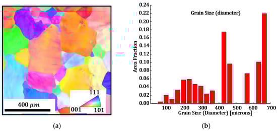
Figure 1.
Initial microstructure of the as-received CoCrFeMnNi rod blank: (a) grain microstructure; (b) grain size.

Table 1.
Main chemical composition of CoCrFeMnNi (wt%).
To characterize the hot flow behavior of HEA, a cylindrical specimen was machined from an as-casted billet for Gleeble testing. The diameter was 8 mm and height was 12 mm, exhibiting a high degree of thermodynamic stability and excellent malleability, and the standard dimension can avoid buckling during compression and ensure the accuracy of stress–strain results.
2.2. Test Program
A series of hot compression tests were performed at the Gleeble 3800 thermal-mechanical simulator (Poestenkill, New York, NY, USA) at different temperatures and strain rates. These tests were completed at the Beijing Institute of Aeronautical Materials and the test atmosphere is in the air. Due to the robust temperature control using electrical resistance heating of Gleeble, the test temperature can be controlled with °C, which provides the assurance of temperature accuracy for high-temperature compression experiments. Through this, the temperature variation during hot compression can be captured by the Gleeble simulator.
Before the hot compression process, the end surface of the specimen was covered with graphite flakes for lubrication to reduce the interfacial friction between the anvil and the specimen. To avoid temperature overshoot during the current heating process, the specimen was firstly heated at a rate of 5 °C/s to a value 100 °C lower than the deformation temperature. Then the specimen was further heated to the target temperature using a slower heating rate of 2 °C/s and kept soaking for 1 min to ensure temperature uniformity before compression tests. The test temperature contains 950 °C, 1000 °C and 1050 °C, and the strain rates were 0.001/s, 0.01/s and 0.1/s. All specimens were compressed to a true strain level of 0.5 at a specific combination of temperature and strain rate. The specimens were cooled to room temperature by air cooling after the completion of the test.
3. Material Model
In this study, a physical-based model scheme was selected enabling the physical internal variables to be introduced into the equations. Both macroscopic flow behavior and corresponding microstructure evolutions, i.e., dislocation density, grain size and recrystallisation [18], can be cooperatively modelled. The model is based on establishing the rate equation and the iteration of each physical internal variable by using the Euler method [19], which is a highly effective method for modelling materials, especially for the complex physical phenomena involved in the hot forming process.
3.1. Adiabatic Heating Modelling
During hot bulk forming, an adiabatic heating effect due to the influence of external force on the billet cannot be ignored, as the increase of temperature would result in the softening of flow stress and variation of microstructure. Strain rate is the governing factor affecting the extent of the adiabatic heating. For a lower strain-rate range (<10−3), the process can always be treated as isothermal, i.e., the material does not undergo a significant temperature rise during the deformation process, considering a sufficiently long time is given for the heat dissipation. However, high strain-rate deformation is often adiabatic, due to the lack of heat transfer, a portion of the deformation work is transferred into heat resulting in the attendant temperature increase. In addition, this process may be accompanied by instabilities of the deformation process (e.g., adiabatic shear), which may cause significant differences between the experiment and its numerical model. The temperature rise in the specimen can be estimated by the following Equation (1):
where is the fraction of heat conversion usually taken as 0.9 [20,21,22], which implies that 90% of the work of plastic deformation is changed to heat. and are mass density and specific heat for alloy, respectively. The mass density for the CoCrFeMnNi is 804.2 kg/m3, and the specific heat is 430 J/(kg·K) [23]. To distinguish dislocation density and mass density, mass density is replaced by the symbol . The specific value of the temperature rise can be calculated mathematically. In this study, to form a complete set of internal variable models, Equation (1) is being derivative, establishing the temperature rise rate equation, which is given in the following Equation (2):
where is strain-induced temperature rise. For isothermal conditions, the instantaneous temperature T is equal to the initial temperature without variation, Ideally. However, for bulk forming processes, the billet normally experiences large deformation that arises a significant temperature increase that cannot be ignored. The instantaneous temperature T equals ( + ), where can be calculated by Equation (2), which can be seen that strain and stress are two main factors determining the instantaneous temperature. To keep a consistent form of equations, the rate form of temperature rise is used.
To precisely simulate the actual changes of the material temperature during the hot bulk forming, the dissipation of heat should be simultaneously considered with the temperature rise. It is necessary to establish the temperature rise and heat dissipation balance mechanism, i.e., the adiabatic and heat dissipation equations, which can enable the prediction of the changes in the specimen temperature during testing at different strain rates. The heat dissipation equation still considers the stress strain as the main influence factor, and a simple one-dimensional function is chosen to form the heat dissipation equation, which is given as follows:
where a and b are fitting coefficients, integrating Equation (2) with Equation (3) to form a total temperature variation equation, which is used to predict the general temperature variation of the specimen in hot compression experiments. The total temperature variation equation is given as follows:
3.2. Unified Viscoplastic Constitutive Equations
The dislocation-based viscoplastic constitutive equations have been developed for many metals and alloys under hot forming conditions. The equations consider the interactive influences between macroscopic flow and corresponding microstructure variations, which include work hardening resulting from dislocation variation and dynamic softening due to thermal activation [24], providing an accurate description of the hot flow behavior and microstructure evolution. In this subsection, the viscoplastic constitutive equations of the model set for the CoCrFeMnNi HEA are discussed.
Equation (5) is the viscoplastic flow rule, given in the form of a strain rate equation. The plastic strain rate considers the grain size evolution and work hardening of the material during deformation, especially at high temperature. In Equation (5), k, K and
are the temperature-dependent constants, is the normalized average grain size, R is the hardening amount [25] and is the temperature-independent constant.
Equation (6) is the isotropic hardening rate equation to describe the variation of hardening. Sandstrom and Lagneborg pointed out that material hardening is correlated directly with dislocation density [26], further establishing Equation (6), where B is a temperature-depended material constant, is the actual dislocation density and is the normalized dislocation density of the material, varying from 0 at the beginning of the deformation and increasing as the deformation progresses until saturation (1) [27].
Equation (7) is the normalized dislocation density rate equation considering the recrystallization effect on dislocation densities, where , , and are temperature-dependent coefficients. and represent the recrystallization volume friction and its rate form.
Equation (8) is the critical dislocation equation that determines the occurrence of the recrystallization, i.e., the recrystallization of the material begins when the current dislocation density is higher than the critical dislocation, where and are the temperature-dependent constants.
Equation (9) is the recrystallization rate equation, where is a material constant and is a temperature-depended coefficient. is normalized grain size and equal to , where is the initial grain size and d is the current grain size.
Equation (10) is the grain size rate equation to describe the evolution of the material during deformation, where , and are temperature-dependent coefficients. , , , and are material constants.
Equation (11) is the stress–strain equation based on 1D Hook law, where is total strain, can be described for the macroscopic flow stress–strain of the material, including elastic strain and plastic strain, and E is Young’s modulus.
A set of constitutive equations based on the above physical variable models are used to fit the hot compression flow curves of the CoCrFeMnNi at different conditions. The equations expressed through the Arrhenius relationship [28] in Table 2 are all temperature-dependent material constants and these coefficients can be used to achieve acceptable comparing results between modeling prediction and experimental results, where Q is the activation energy and R is the gas constant.
Table 2.
The equation set of temperature-dependent material constants.
4. Results and Discussion
4.1. Adiabatic Heating during Hot Compression Tests
The adiabatic heating during the Gleeble hot compression tests was quantified by the record of the real-time temperature values of the specimen. Figure 2 describes adiabatic heat, dissipate heat and the comparison of experimental temperature variations and total temperature equation fitted predictions at different strain rates.
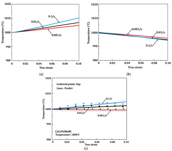
Figure 2.
Comparison of experimental temperature variations and fitted predictions for different strain rates of Gleeble hot compression tensile testing: (a) adiabatic heat; (b) dissipate heat; (c) total temperature variation. The target testing temperature is 1000 °C.
Figure 2a gives the comparison of the temperature increment due to adiabatic heating for three strain rates of 0.001/s, 0.01/s and 0.1/s. It can be seen that the higher strain rate leads to the higher temperature increment—the heat generation failing to dissipate in time at a fast deformation rate, resulting in a large temperature increment. However, the deformation heat loss is more at the low strain rate, leading to a slight change in temperature increment. Figure 2b gives the predicted temperature dissipation for different strain rates by established heat dissipation in Equation (3), which is obtained by back-propagating the total temperature in Equation (4). In Figure 2b, the higher strain rate leads to faster heat dissipation, which can effectively balance the temperature rise due to adiabatic heating.
The comparison between the experimental temperature variations and the prediction of total temperature variation according to Equation (4) is shown in Figure 2c, where the scatter plot is the variation of the macroscopic temperature of the compression experiment at three strain rates recorded by a Gleeble thermal simulator, and the line plot is the prediction result of the total temperature equation developed in this paper. As shown in this figure, a higher strain rate leads to higher actual macroscopic temperature rise of the material, which corresponds to the adiabatic heating-induced temperature rise at different strain rates in Figure 2a.
To examine the reliability of the proposed model’s prediction results and experimental data of the total temperature variation, R-value and AARE are calculated to provide a strong description according to the following equation:
where and are experimental and predictable temperature, and are the mean of experimental temperature and N is the number of data. The R-value represents the linearity between experimentation and prediction. An R value of 1 indicates that simulation results perfectly coincide with experimental results. Hence, a higher R-value implies better correlation between the experiment and the prediction, reflecting the accuracy of the model’s prediction. The calculated R values in Figure 2c are 0.8926 (0.001/s), 0.8537 (0.01/s) and 0.85405 (0.1/s). The R-value is maximum at the strain rate of 0.001/s, indicating that the model is more relevant to the experiment under this condition. For all three conditions, the R-values were greater than 0.85, indicating that the fittings of the models are acceptable. The AARE represents the deviation of the experiment and predictions, the smaller the AARE is, the smaller the error of prediction temperature is, and the corresponding AARE is 0.0103, 0.0224, 0.0254. The AARE is minimum at a strain rate of 0.001/s, reflecting the minimum deviation between model predictions and experimental results. Both R-value and AARE reflect the accuracy of the predictive description of the total temperature variation calculated in this paper.
4.2. Hot Deformation of HEA
The material flow behavior in hot deformation is very complex that is affected by the coupled effects of dynamic softening, i.e., DRX and recovery and work hardening, i.e., dislocation density accumulation. This subsection discusses the results of the hot flow behavior of HEA, model predictions and the analysis of hardening performance.
4.2.1. Hot Flow Behavior of HEA
Figure 3 compares hot compression behavior between constitutive model prediction (solid lines) and experimental results (scattered points). The comparison results are divided in Figure 3. Figure 3a is the results under a temperature 1000 °C (0.001/s, 0.1/s and 0.1/s), and Figure 3b is the results under strain rates 0.01/s (950 °C, 1000 °C and 1050 °C). The good agreement of the fitting performance can be seen from the two result figures, with the hardening stage (dislocation accumulation) and softening stage (dynamic recrystallization) of the stress–strain curves under different conditions. All the curves show a similar trend that the peak of the flow stress increases as the strain rate increases and the deformation temperature decreases, which due to the high strain rate causes fast dislocation accumulation, and recrystallization and dynamic recovery are not activated at a low temperature, which leads to a high-stress level.
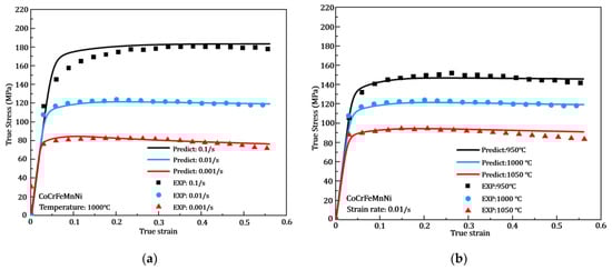
Figure 3.
Comparisons of hot flow results under hot compression tests between experimentation and model computations results at various deformation conditions. (a) Strain rate effect at 1000 °C. (b) Temperature effect at 0.01/s.
From all the stress–strain curves of the hot deformation process in Figure 3, a huge slope of the curve can be seen at the initial stage and the curve becomes slightly flattened or even show a decrease at the later stage of deformation as the strain increases. Because in the initial stage of deformation, work hardening is produced due to the drastic increase in dislocation density [29], but with the further deformation, the material goes from the elastic stage to the plastic deformation stage, and the stress growth becomes slower, while the combined effect of temperature and strain rate causes the stress level to decrease to some extent.
In Figure 3a, the softening phenomenon at strain rate 0.01/s is significant at 1000 °C, which leads to a reduction in the material flow stress, while in Figure 3b, the softening behavior of the material at strain rate 0.01/s is most obvious at 1050 °C. Considering the flow stress, the lower strain rates and higher temperatures reduce the flow stress values. Lower strain rates lead to longer deformation that facilitates the dislocation recovery and reduces deformation resistance; hence, resulting in lower flow stress. Higher temperature lead to recrystallization, and annealing will both reduce the dislocation density and, thus, reduce the working hardening behavior resulting in lower flow stress.
The R-value between experimental results and prediction of flow stress calculated from Figure 3a,b is 0.95819 (0.001/s), 0.99454 (0.01/s), 0.98505 (0.1/s) and 0.99215 (950 °C), 0.98505 (1000 °C), 0.98461 (1050 °C), respectively. The corresponding AARE are 0.03906, 0.0152, 0.04618 and 0.01754, 0.04618, 0.03114, respectively. The maximum R-value is 0.99454 and minimum AARE is 0.0152 at 1000 °C of 0.01/s, meaning that the flow stress–strain deducted by the modelling under this condition is closely matched with the experimental results. Moreover, the R-value is greater than 0.95 and the AARE value is less than 0.05 for all conditions, which reflect the accuracy of the modelling prediction for the hot flow behavior of the CoCrFeMnNi high-entropy alloy developed in this paper. The determined material constants used in the unified viscoplastic equations from the fitting of the flow stress curves are given in Table 3.
Table 3.
The determined constants for unified viscoplastic equation.
4.2.2. Hardening Evolution
Hardening is an extremely important property during hot bulk forming. The bulk processes normally prefer a lower strain-hardening behavior for the sake of avoiding severe working load. Figure 4 gives the hardening performance of the CoCrFeMnNi under hot compression tests, where Figure 4a shows the strain hardening component, n, and maximum flow stress under different temperatures of the same strain rate. Figure 4b shows the hardening rate under different strain rates of the same temperature.
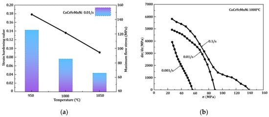
Figure 4.
Hardening performance of the CoCrFeMnNi: (a) strain hardening component, n, (b) the hardening rate at 1000 °C (0.001/s, 0.01/s and 0.1/s).
In Figure 4a, the n value given in the bar graph shows a decrease with increasing temperature at the same strain rate, with maximum and minimum n values of 0.153 and 0.043 for 950 °C and 1050 °C. In addition, the maximum flow stress given in the line graph shows the same trend with the n value, with a maximum flow stress of 147.12 MPa and a minimum of 94.64 MPa. Figure 4b shows the hardening rate under different strain rates by using the vs. curves [30]; as expected, the hardening rate value starts at a very high value and gradually decreases to zero. This indicates that the hardening effect of the material dominates at the early stage of deformation, and the effect gradually decreases, and the softening effect gradually dominates the deformation. In addition, high strain rate will lead to a high hardening rate determined by the strain rate strengthening mechanism. However, high dislocation density is the main reason for material work hardening leading to increased flow stress. When the plastic strain accumulates to a certain degree, the hardening behavior is reduced and the material softening behavior is dominant.
4.3. Model Verification of Grain Microstructure
Electron backscattered diffraction (EBSD) was used to characterize the grain size both before and after testing. This allowed quantitative measurements of the mean grain size.
Figure 5 gives the EBSD microstructure observations of different conditions. Figure 5a,b is the microstructure of strain in 0.2 and 0.5 at temperature of 1000 °C and strain rate of 0.01/s. In Figure 5a, most of the area is green with some purple and red, indicating a transition of grain boundary orientation causing dislocation accumulation, while in Figure 5b, a large area is green with clearly nucleated grain at the grain boundary illustrating recrystallization occurred in this condition. Comparing Figure 5a,b, combined with the prediction of grain size in Figure 6, shows that the grain size is smaller at a higher strain for the same temperature and strain rate. Figure 5c gives the corresponding microstructure at 1000 °C−0.1/s−0.5, which clearly shows that the red and purple colors are more apparent, meaning more dislocation accumulation, and a small number of new grain nucleation can be observed at the grain boundary. This is a consequence of a short soaking time at a high strain rate, which fails to provide sufficient time for apparent recrystallization to occur; however, the slight recrystallization did compare with the low strain rate and the small amount of new grain nucleation at higher temperature and deformation.

Figure 5.
EBSD microstructure observations of different conditions: (a) 1000 °C–0.01/s–0.2; (b) 1000 °C–0.01/s–0.5; (c)1000 °C–0.1/s–0.5.
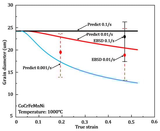
Figure 6.
Comparisons of grain size between EBSD obversion and model results in various deformation conditions.
Figure 6 gives the EBSD grain size observations of typical conditions of 1000 °C–0.01/s–0.2, 1000 °C–0.01/s–0.5 and 1000 °C–0.1/s–0.5 to show the trend. The strain rate 0.001/s was not experimentally observed, so only the predicted result was given. EBSD observations were performed for the same conditions in Figure 5, giving the effect of strains and strain rates on the grain size evolution. For clarity, the error bars in the figure come from statical analysis on the grain sizes from the EBSD figure and can reflect the nature of the grain size distributions. Predicted curves within the error bar is considered acceptable. EBSD results are given in the form of error bars, and grain size evolution predicted by the modelling is within the observed range of EBSD results, which show the accuracy of the model predictions. The model predictions show that the grain size tends to become smaller as the strain accumulates. Particularly, the largest change in grain size was observed at 0.001/s, from original 23.91 to 5.76 . This is due to the refinement of grain size by recrystallization under a lower strain rate, and a lower strain rate leads to a longer soaking time at the high temperature deformation, leading to a more sufficient recrystallization time and the large change in grain size. However, the grain size shows no obvious change at a strain rate of 0.1/s, due to the fast deformation generating a large number of dislocations. However, the necessary soaking time is the key to triggering recrystallization, while a high strain rate lead to a short deformation time (within seconds), which may not provide sufficient energy for recrystallization to occur. Hence, no obvious grain size change may occur as predicted in the figure under this condition.
To further understand the material properties, the evaluation of fracture toughness, residual stress on the local scale is very important. Ghidelli et al. [31] proposed micro-cantilever and micro-pillar test configurations to evaluate the local fracture toughness of material on the fine dimensional scale. In addition, the researchers [32] developed a fully analytical model for the simultaneous extraction of the elastic moduli and residual stresses in the two layers, which greatly helps in understanding and evaluating materials. The submicroscale measures of material properties also play a driving role in future research on new materials.
5. Conclusions
In this paper, a novel physical mechanism-based constitutive model of CoCrFeMnNi high-entropy alloy was established, which particularly considers the adiabatic heating during bulk forming processes. This provides the necessary optimization methods for optimizing the parameters of the bulk forming processes.
- The validity of the model both in the sense of macroscopic flow behavior and microscopic evolution, while the developed adiabatic and heat dissipation equations well describe the variation of the heat of deformation at different rates of this alloy.
- The applied adiabatic and proposed heat dissipation equation can describe the variation of the temperature for the CoCrFeMnNi high-entropy alloy under Gleeble hot compression tests. The comparison of temperature variation between experiment and prediction at three strain rates (0.001/s, 0.01/s and 0.1/s) of 1000 °C obtains a good agreement by calculating R-value (all higher than 0.85) and AARE (all lower than 0.03).
- The flow behavior of the CoCrFeMnNi high-entropy alloy at different temperatures (950 °C~1050 °C) and strain rates (0.001/s~0.1/s) was determined using the physical mechanism-based constitutive model. The results of R-value and AARE show the excellent prediction at all different conditions. Meanwhile, the hardening performance (strain hardening and hardening rate) are enhanced with higher strain rates and lower temperatures. This provides great help to study the flow behavior and the corresponding properties of the CoCrFeMnNi at high temperature.
- The EBSD microstructure observations and model fitting results of grain size evolution reveal that at the same temperature and strain, the higher the strain rate, the more dislocation accumulation. However, smaller strain rate results in more evident recrystallization and smaller grain size.
Author Contributions
The study in this paper was performed as a collaboration between all the authors. S.Q., Y.F. and K.Z. designed the program of experiment and discussed the relevant details. J.-H.Z. and K.Z. provided scientific guides. Y.F. performed the hot compression tests. S.Q., Y.F., J.L. and K.Z. established a suitable material constitutive model. S.Q., K.Z. and J.-H.Z. wrote the manuscript. All authors have read and agreed to the published version of the manuscript.
Funding
The authors would like to thank the funding support by the Fundamental Research Funds for the Central Universities under the Grant Agreement DUT20RC(3)012. Thanks to the funding from the National Natural Science Foundation of China (Grant No. 52105359).
Institutional Review Board Statement
Not applicable.
Informed Consent Statement
Informed consent was obtained from all subjects involved in the study.
Data Availability Statement
The raw/processed data required to reproduce these findings cannot be shared at this time as the data also forms part of an ongoing study.
Conflicts of Interest
The authors declare no conflict of interest.
References
- Yeh, J.W.; Chen, S.K.; Lin, S.J.; Gan, J.Y.; Chin, T.S.; Shun, T.T.; Tsau, C.H.; Chang, S.Y. Nanostructured High-Entropy Alloys with Multiple Principal Elements: Novel Alloy Design Concepts and Outcomes. Adv. Eng. Mater. 2004, 6, 299–303. [Google Scholar] [CrossRef]
- Li, Z.; Ludwig, A.; Savan, A.; Springer, H.; Raabe, D. Combinatorial Metallurgical Synthesis and Processing of High-Entropy Alloys. J. Mater. Res. 2018, 33, 3156–3169. [Google Scholar] [CrossRef]
- Zhang, Y.; Zuo, T.T.; Tang, Z.; Gao, M.C.; Dahmen, K.A.; Liaw, P.K.; Lu, Z.P. Microstructures and Properties of High-Entropy Alloys. Prog. Mater. Sci. 2014, 61, 1–93. [Google Scholar] [CrossRef]
- Yamabe-Mitarai, Y.; Yanao, K.; Toda, Y.; Ohnuma, I.; Matsunaga, T. Phase Stability of Ti-Containing High-Entropy Alloys with a Bcc or Hcp Structure. J. Alloys Compd. 2022, 911, 164849. [Google Scholar] [CrossRef]
- Feng, R.; Gao, M.C.; Zhang, C.; Guo, W.; Poplawsky, J.D.; Zhang, F.; Hawk, J.A.; Neuefeind, J.C.; Ren, Y.; Liaw, P.K. Phase Stability and Transformation in a Light-Weight High-Entropy Alloy. Acta Mater. 2018, 146, 280–293. [Google Scholar] [CrossRef]
- Kini, M.K.; Lee, S.; Savan, A.; Breitbach, B.; Addab, Y.; Lu, W.; Ghidelli, M.; Ludwig, A.; Bozzolo, N.; Scheu, C.; et al. Nanocrystalline Equiatomic CoCrFeNi Alloy Thin Films: Are They Single Phase Fcc? Surf. Coat. Technol. 2021, 410, 126945. [Google Scholar] [CrossRef]
- Wu, G.; Liu, C.; Brognara, A.; Ghidelli, M.; Bao, Y.; Liu, S.; Wu, X.; Xia, W.; Zhao, H.; Rao, J.; et al. Symbiotic Crystal-Glass Alloys via Dynamic Chemical Partitioning. Mater. Today 2021, 51, 6–14. [Google Scholar] [CrossRef]
- Cantor, B.; Chang, I.T.H.; Knight, P.; Vincent, A.J.B. Microstructural Development in Equiatomic Multicomponent Alloys. Mater. Sci. Eng. A 2004, 375–377, 213–218. [Google Scholar] [CrossRef]
- Laplanche, G.; Kostka, A.; Horst, O.M.; Eggeler, G.; George, E.P. Microstructure Evolution and Critical Stress for Twinning in the CrMnFeCoNi High-Entropy Alloy. Acta Mater. 2016, 118, 152–163. [Google Scholar] [CrossRef] [Green Version]
- Gludovatz, B.; Hohenwarter, A.; Catoor, D.; Chang, E.H.; George, E.P.; Ritchie, R.O. A Fracture-Resistant High-Entropy Alloy for Cryogenic Applications. Science 2014, 345, 1153–1158. [Google Scholar] [CrossRef] [Green Version]
- Huang, S.; Li, W.; Lu, S.; Tian, F.; Shen, J.; Holmström, E.; Vitos, L. Temperature Dependent Stacking Fault Energy of FeCrCoNiMn High Entropy Alloy. Scr. Mater. 2015, 108, 44–47. [Google Scholar] [CrossRef]
- Jeong, H.T.; Park, H.K.; Park, K.; Na, T.W.; Kim, W.J. High-Temperature Deformation Mechanisms and Processing Maps of Equiatomic CoCrFeMnNi High-Entropy Alloy. Mater. Sci. Eng. A 2019, 756, 528–537. [Google Scholar] [CrossRef]
- Zerilli, F.J.; Armstrong, R.W. Dislocation-Mechanics-Based Constitutive Relations for Material Dynamics Calculations. J. Appl. Phys. 1987, 61, 1816–1825. [Google Scholar] [CrossRef] [Green Version]
- Patnamsetty, M.; Saastamoinen, A.; Somani, M.C.; Peura, P. Constitutive Modelling of Hot Deformation Behaviour of a CoCrFeMnNi High-Entropy Alloy. Sci. Technol. Adv. Mater. 2020, 21, 43–55. [Google Scholar] [CrossRef] [PubMed] [Green Version]
- Wang, B.; Fu, A.; Huang, X.; Liu, B.; Liu, Y.; Li, Z.; Zan, X. Mechanical Properties and Microstructure of the CoCrFeMnNi High Entropy Alloy under High Strain Rate Compression. J. Mater. Eng. Perform. 2016, 25, 2985–2992. [Google Scholar] [CrossRef]
- Johnson, G.R.; Cook, W.H. A Computational Constitutive Model and Data for Metals Subjected to Large Strain, High Strain Rates and High Pressures. In Proceedings of the Seventh International Symposium on Ballistics, The Hague, The Netherlands, 19–21 April 1983. [Google Scholar]
- Brown, C.; McCarthy, T.; Chadha, K.; Rodrigues, S.; Aranas, C.; Saha, G.C. Constitutive Modeling of the Hot Deformation Behavior of CoCrFeMnNi High-Entropy Alloy. Mater. Sci. Eng. A 2021, 826, 141940. [Google Scholar] [CrossRef]
- Lin, Y.C.; Chen, X.M. A Critical Review of Experimental Results and Constitutive Descriptions for Metals and Alloys in Hot Working. Mater. Des. 2011, 32, 1733–1759. [Google Scholar] [CrossRef]
- Lin, J.; Liu, Y. A Set of Unified Constitutive Equations for Modelling Microstructure Evolution in Hot Deformation. J. Mater. Processing Technol. 2003, 143, 281–285. [Google Scholar] [CrossRef]
- Bai, Q.; Lin, J.; Dean, T.A.; Balint, D.S.; Gao, T.; Zhang, Z. Modelling of Dominant Softening Mechanisms for Ti-6Al-4V in Steady State Hot Forming Conditions. Mater. Sci. Eng. A 2013, 559, 352–358. [Google Scholar] [CrossRef]
- Park, J.M.; Moon, J.; Bae, J.W.; Jang, M.J.; Park, J.; Lee, S.; Kim, H.S. Strain Rate Effects of Dynamic Compressive Deformation on Mechanical Properties and Microstructure of CoCrFeMnNi High-Entropy Alloy. Mater. Sci. Eng. A 2018, 719, 155–163. [Google Scholar] [CrossRef]
- Sung, J.H.; Kim, J.H.; Wagoner, R.H. A Plastic Constitutive Equation Incorporating Strain, Strain-Rate, and Temperature. Int. J. Plast. 2010, 26, 1746–1771. [Google Scholar] [CrossRef]
- Dodd, B. Adiabatic Shear Localization: Frontiers and Advances; Elsevier: Amsterdam, The Netherlands, 2012. [Google Scholar]
- Khan, A.S.; Kazmi, R.; Farrokh, B.; Zupan, M. Effect of Oxygen Content and Microstructure on the Thermo-Mechanical Response of Three Ti-6Al-4V Alloys: Experiments and Modeling over a Wide Range of Strain-Rates and Temperatures. Int. J. Plast. 2007, 23, 1105–1125. [Google Scholar] [CrossRef]
- Garrett, R.P.; Lin, J.; Dean, T.A. An Investigation of the Effects of Solution Heat Treatment on Mechanical Properties for AA 6xxx Alloys: Experimentation and Modelling. Int. J. Plast. 2005, 21, 1640–1657. [Google Scholar] [CrossRef]
- Sandsttom, R.; Lagneborgt, R. A model for hot working ocgurring by recrystallization. Acta Metall. 1975, 23, 387–398. [Google Scholar] [CrossRef]
- Lin, J.; Dean, T.A. Modelling of Microstructure Evolution in Hot Forming Using Unified Constitutive Equations. J. Mater. Processing Technol. 2005, 167, 354–362. [Google Scholar] [CrossRef]
- Jensen, F. Activation energies and the arrhenius equation. Qual. Reliab. Eng. Int. 1985, 1, 13–17. [Google Scholar] [CrossRef]
- Li, A.; Huang, Z.; Xu, H.; Wei, S. Effects of C and La on the Tensile Property and Hot Working Characteristics of CoCrFeMnNi High-Entropy Alloy. In Journal of Physics: Conference Series; IOP Publishing Ltd.: Bristol, UK, 2020; Volume 1622. [Google Scholar]
- Zheng, J.H.; Pruncu, C.; Zhang, K.; Zheng, K.; Jiang, J. Quantifying Geometrically Necessary Dislocation Density during Hot Deformation in AA6082 Al Alloy. Mater. Sci. Eng. A 2021, 814, 141158. [Google Scholar] [CrossRef]
- Ast, J.; Ghidelli, M.; Durst, K.; Göken, M.; Sebastiani, M.; Korsunsky, A.M. A Review of Experimental Approaches to Fracture Toughness Evaluation at the Micro-Scale. Mater. Des. 2019, 173, 107762. [Google Scholar] [CrossRef]
- Ghidelli, M.; Sebastiani, M.; Collet, C.; Guillemet, R. Determination of the Elastic Moduli and Residual Stresses of Freestanding Au-TiW Bilayer Thin Films by Nanoindentation. Mater. Des. 2016, 106, 436–445. [Google Scholar] [CrossRef]
Publisher’s Note: MDPI stays neutral with regard to jurisdictional claims in published maps and institutional affiliations. |
© 2022 by the authors. Licensee MDPI, Basel, Switzerland. This article is an open access article distributed under the terms and conditions of the Creative Commons Attribution (CC BY) license (https://creativecommons.org/licenses/by/4.0/).