Abstract
Similarity laws of scaled models of offshore platform deck structures under low velocity impact loading are proposed in the present research. The similarity laws of scaled models with different scaling factors are established in forms of dimensionless factors with consideration of flow stress differences of the materials. A dimensionless displacement is defined by dividing displacement by plate thickness and a dimensionless force is defined by dividing force by flow stress and plate thickness; then, a dimensionless force-displacement relationship is established. Dynamic responses of three geometrically similar stiffened structures with scaling factors of 1:4, 1:2, and 1:1 subjected to the dropping impact of a rigid triangular pyramidic impactor are investigated by an experimental test and a finite element analysis. Results show that dimensionless force-displacement curves of geometrically similar plates coincide with each other; meanwhile, the difference of maximum impact force for the three structures with various scaling factors is less than 5%, and the difference of maximum impact depth is less than 1%, which definitely show the effectiveness of the scaling laws based on dimensionless factors. The present research provides useful insight into the similarity laws of dynamic responses of deck structures subjected to falling object impact and would be used in the crashworthiness research and design process of the offshore structures.
1. Introduction
Low velocity impacts of ships and offshore structures, including collision and grounding, floating object collision and falling object impact, are prone to catastrophic disasters. Thus, researchers worldwide pay particular attention to investigations of ship structure collisions, as plenty of useful conclusions have been obtained by analytical investigations, numerical research and experimental tests [1,2]. Among these investigations, important factors such as impact load, stress distribution, damage initiation and propagation would be obtained by experimental research; furthermore, experimental test results provide benchmark studies for numerical simulations and analytical research. Thus, experimental methods play an irreplaceable role in collision research.
A small-scaled model test has been mainly adopted in ship collision research for the purpose of reducing difficulty and economic consumption [3,4]. One of the most important factors is to establish the similarity laws between the scaled model and the prototype. Jones [5] proposed the similarity law to transfer the scaling model impact test results into the prototype impact results. Calle [6] proposed a scaling law with consideration of material yield, material strain hardening, damage initiation and strain rate effect.
The above-mentioned research provides support for the extension of scale model test results to full-scaled prototypes for ship collisions. However, the research mentioned above mainly focuses on collisions of ship side structures, and few investigations have been proposed on research of deck structures under the impact of dropping objects; thus, similarity laws of structure models with different scaling factors should be considered. The present research conducts tests on similarity laws of scaled models of an offshore platform deck structure under low velocity impact of dropping objects. The first step is to propose the similarity laws between a small-scaled model and a full-scaled prototype, and to introduce a couple of dimensionless factors; the following step is to establish three geometrically similar stiffened plate structures with different scaling factors; then, experimental and numerical simulation research on low velocity impact has been completed and the last step is to analyze the experimental and numerical results with the dimensionless factors. Finally, the similarity laws are verified.
2. Similarity Laws
Generally, a dynamic impact test is conducted on a geometrically similar small-scaled model to obtain dynamic responses with consideration of economical consumption. In this series of research, a prototype means a model which is the same as the stiffened plate of a real offshore structure; they have the same length, width, the same shell thickness, the same stiffeners and the same stiffener spaces. Meanwhile, the scaled model is geometrically similar to the prototype, whereas they are of the same shape but a different size. Furthermore, the scaled models and the prototype are usually manufactured with the same material and the same fabrication method.
Thus, the first priority is to establish scaling principles between scaled model and prototype. For a full-scaled prototype model and the corresponding geometrically similar small-scaled model, the relationships between the characteristics of the scaled model and the prototype are established by using the scaling factor [5]. The scaling factor between the geometrically similar small-scaled model and the full-scaled prototype is defined as:
where LS means length of the scaled structure and Lp means length of the full-scaled prototype. As well, in a low velocity impact scenario the impact displacement, shell thickness, impact force and energy absorption follow the following scaling principle:
These similarity laws were established under the assumption that the small-scaled model and the full-scaled prototype were fabricated by the same material with the same values of mass density (ρ), elastic module (E), Poisson’s ratio (μ), yield strength (σs) and ultimate strength (σb). However, experimental test results show that yield strength and ultimate strength of the plates with different thicknesses are slightly different in many cases. Thus, the influence of the differences of yield strength should be considered in the scaling laws. Previous experimental and theoretical studies show that the impact force is proportional to the flow stress of the materials [4,7]:
where (σ0) = (σs + σb)/2 means the flow stress of the materials, and which equals to the average value of yield stress and ultimate strength. Thus, the influence of the differences of flow stress should also be considered in the scaling law; an effective way is to establish a couple of dimensionless factors. A dimensionless displacement is defined by dividing displacement by shell thickness and a dimensionless impact force is defined by dividing force by flow stress and shell thickness:
In the same way, the dimensionless energy absorption is also defined as:
In Equations (1)–(8), the symbols with subscript “s” represent the physical quantity of the small-scaled model, whereas the symbols with subscript “p” represent the physical quantity of the full-scaled prototype; the same as below, as shown in Table 1. Theoretically, the dimensionless impact force and energy absorption of the scaled model should be equal to those of the full-scaled prototype under the same dimensionless displacement. In another way, the dimensionless force-displacement curves and dimensionless energy absorption curves of models with different scaling factors should be the same shape.

Table 1.
Meaning of the symbols of small-scaled model and full-scaled prototype.
3. Materials and Methods
Three types of geometrically similar stiffened plate models with different scaling factors were designed, an impact tower for drop weight impact was established, and an FEA (finite element analysis) of the dynamic impact scenarios was conducted for further investigations.
3.1. Specimens
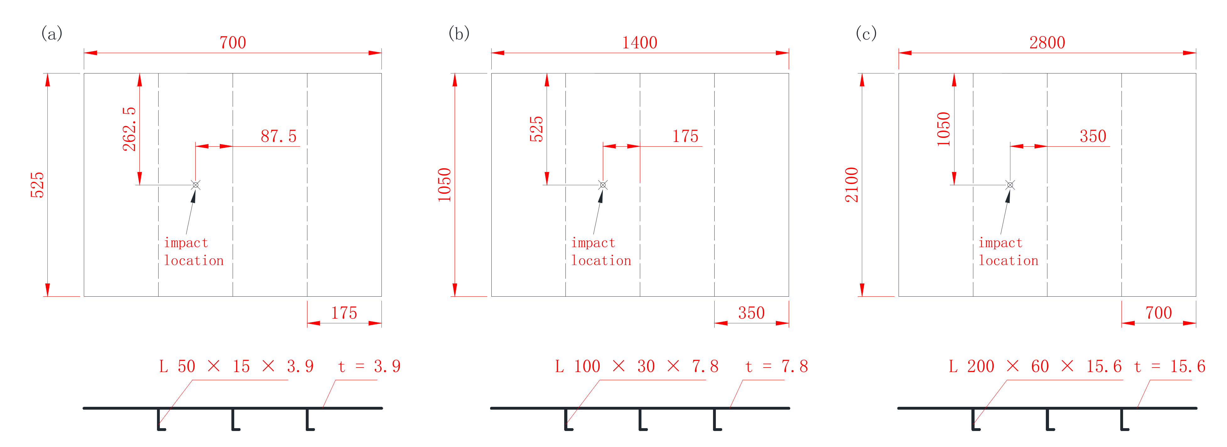
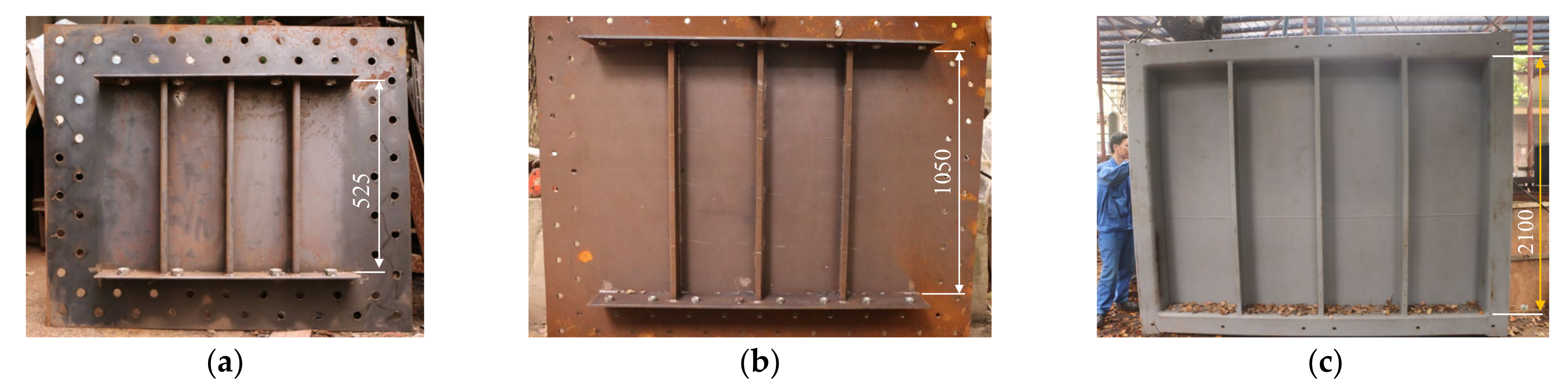
Rectangular stiffened steel plates, which were derived from the deck structure of an offshore platform, were conducted in the present research. Three similar specimens, including two small-scaled models with a 1:4 and a 1:2 scaling factor, and one full-scaled prototype, were proposed. As shown in Figure 1 and Figure 2, three geometrically similar specimens were stiffened by three uniformly distributed L-shaped stiffeners. The thicknesses of the plates were 3.9 mm, 7.8 mm and 15.6 mm, respectively.
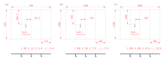
Figure 1.
Geometric configurations of the geometrically similar stiffened plates (unit: mm): (a) 1:4 scaled; (b) 1:2 scaled; (c) full-scaled (“L” means that the stiffeners are angle steel with “L” shaped cross-section, “t” means thickness of the plate).

Figure 2.
Photographs of the specimens (unit: mm): (a) 1:4 scaled model; (b) 1:2 scaled model; (c) full-scaled prototype.
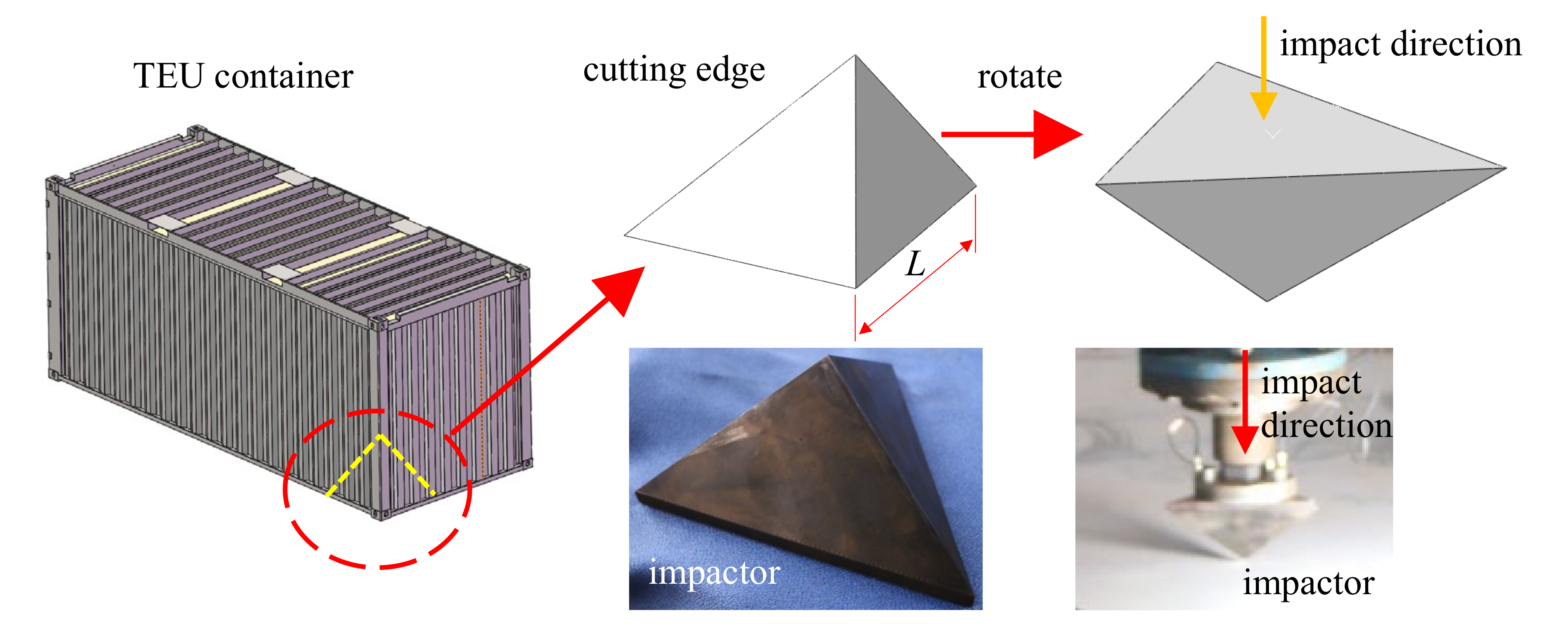
Since the sharp edge of the dropping container would cause deck damage in case of falling, a rigid triangular pyramidic impactor derived from a container was conducted with the length of the edge “L” equal to 200 mm, as shown in Figure 3. The impactor was fabricated with abrasive steel, and a heat treatment process ensured its surface hardness.
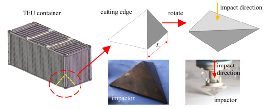
Figure 3.
TEU (Twenty feet Equivalent Unit) container and the triangular pyramidic impactor.
3.2. Experimental Set-Up
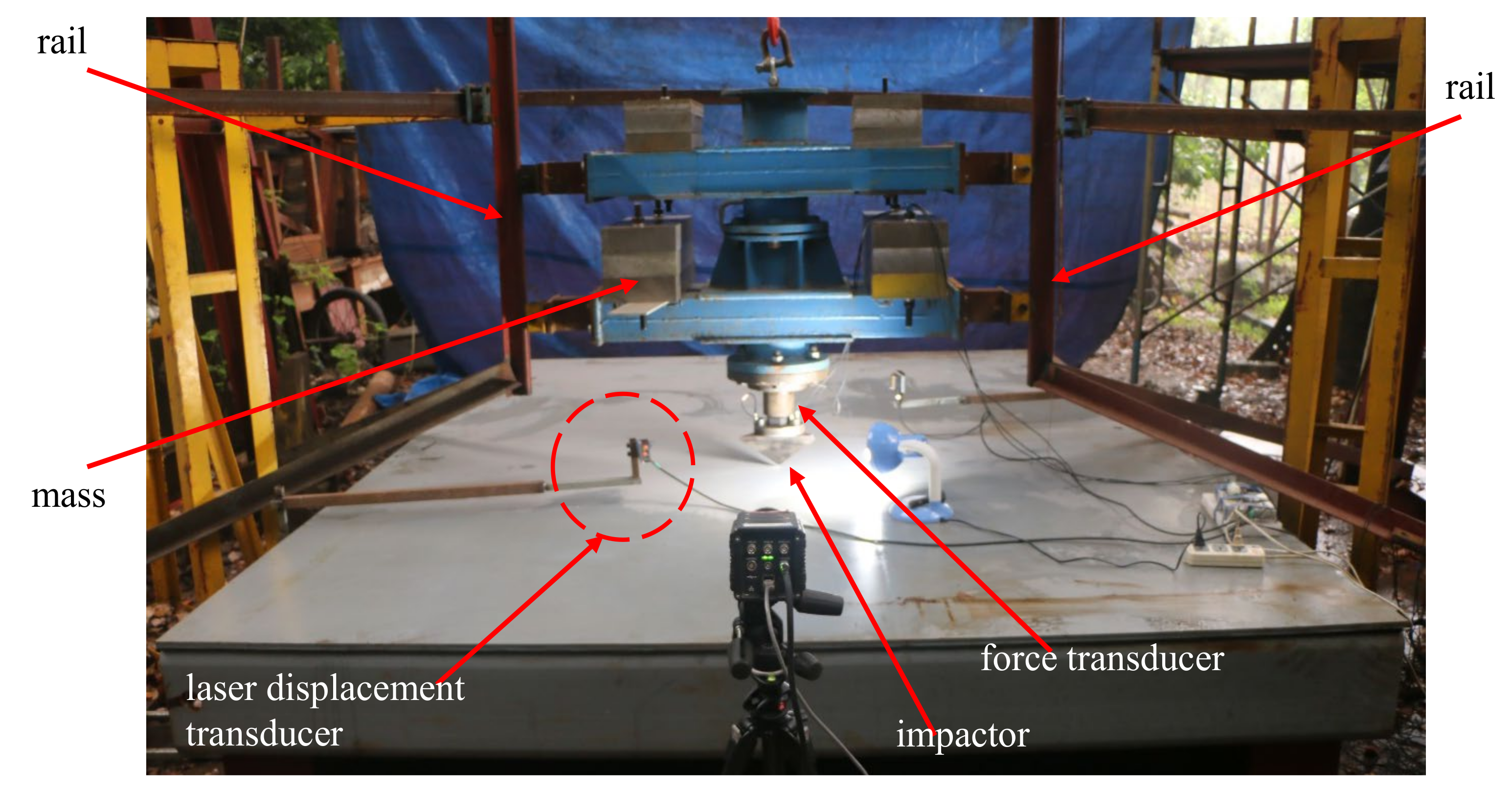
The low velocity impact was carried out by the weight drop impact test tower. As shown in Figure 4, the test specimen was located at the bottom of the tower. In order to prevent the specimen from bounding or sliding away, the specimen was clamped by a dozen of bolts located around the stiffened plate during the impact process. The impactor was guided by two vertical rails and consisted of three parts: an impactor, a force transducer and the mass. During the impact process, the initial impact energy was achieved by adjusting the drop height and the mass property of the impactor; contact force versus time history could be achieved by the piezo-electric force transducer connected to the impactor under a sampling frequency of 40 kHz. The vertical displacement of the impactor was tested by the laser displacement transducer, and furthermore, the initial impact velocity was calculated by the differential of displacement. Then, energy absorption during the impact procedure could be calculated by trapezoidal numerical integration of the force–displacement curve. The piezo-electric force transducer, with a code number of L1100–909543, was fabricated by Xiyuan Electronic Technology Co., Ltd, Yangzhou, China. The laser displacement transducer, with a code number of HG–C 1400, was fabricated by Panasonic Co., Ltd, Kasugai, Japan.
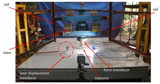
Figure 4.
Weight drop impact test tower.
3.3. Finite Element Method
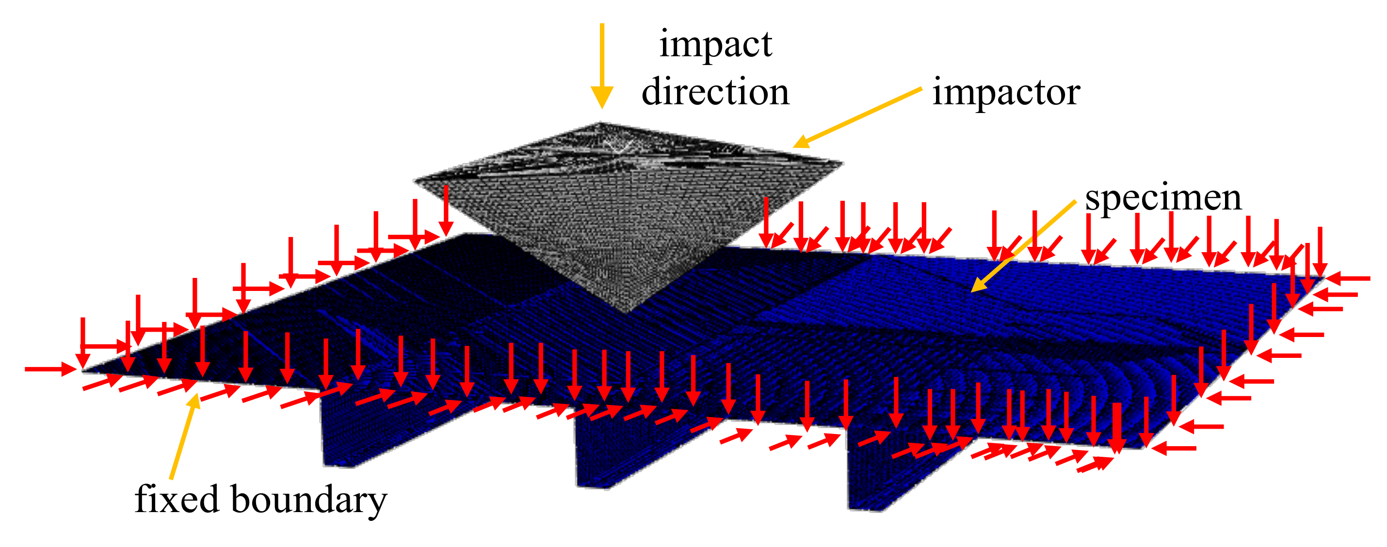
For the numerical simulation of low velocity impact, the commercial package ABAQUS/Explicit with a non-linear explicit algorithm was implemented. As shown in Figure 5, the numerical model consisted of two parts, the impactor and the specimen. The triangular pyramidic impactor was modeled as a rigid body, and a concentrated mass point was defined to simulate the mass of the impactor. The specimens with different scaling factors were modeled by shell model. Marinatos [8] suggested that the aspect ratio of the elements was kept as close as possible to 1:1, and le/t ≤ 1 (where le means the element size, and t means the shell thickness) led to better reproduction of the experimental results; thus, S4R elements (4-node doubly curved shell reduced integration elements) with sizes of 4 mm, 8 mm and 16 mm were used to discretize the specimens in the 1:4 scaled model, the 1:2 scaled model and the full-scaled prototype, respectively. In the numerical models, an automatic surface to surface contact strategy provided by ABAQUS/Explicit (Version 6.11, created by Dassault System, permission from Huazhong University of Science and Techonolgy, Wuhan, China) was selected to simulate the contact problem. The friction coefficient was set to 0.3 for the tangential contact surfaces, which was proven to be efficient to match with the experimental results in previous studies [9,10]. Boundaries of the stiffened plate were modeled as fully clamped, whereas the freedom of the pyramidic impactor was restricted except in the vertical impact direction. Furthermore, a predefined field built into the software was adopted to define the initial impact velocity of the impactor.
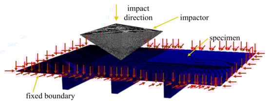
Figure 5.
The finite element model of low velocity impact (the red arrows mean that the freedoms of the boundary in three directions have been fixed).
The built-in ductile damage model built into the ABAQUS software was employed to characterize the mild steel material. Tensile tests were conducted under the guidance of GB/T 228-2002, a metallic materials–tensile test at ambient temperature. The uniaxial tensile tests were implemented by a universal tension test machine with a code number of WAW–600 E, fabricated by Chuance Test Machine Co., Ltd, Jinan, China. A dog-bone specimen shown in Figure 6 was cut down from the plate by wire electrical discharge, and uniaxial tensile curves of the specimens were carried out by the universal tension test machine under a tension velocity of 3 mm/min.
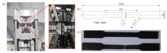
Figure 6.
Quasi-static tensile test of the steel plates: (a) tensile test machine; (b) geometric configurations of the tensile specimen; (c) photograph of the tensile test specimen.
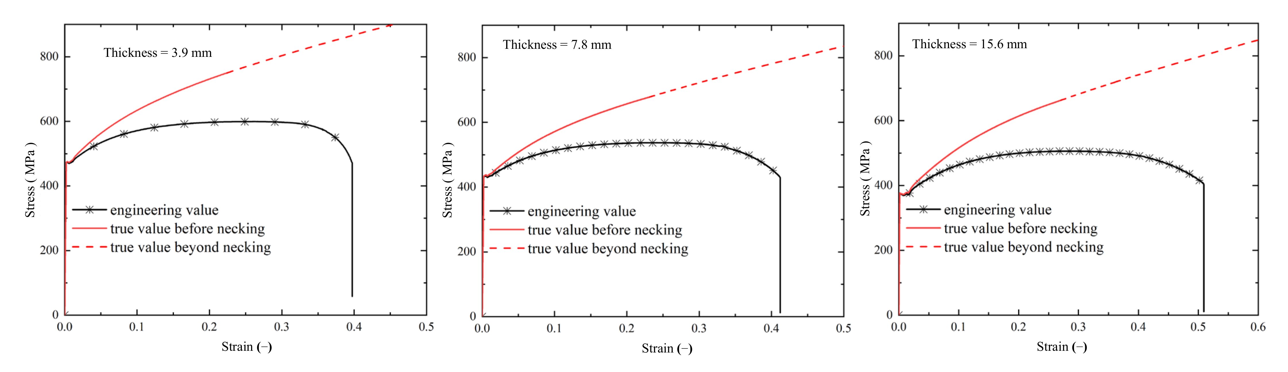
Based on the tensile test results, a combined material relationship was adopted to express the true stress-strain curves. The true stress-strain relationship before necking was proposed as follows:
where εn and σn represent the nominal strain and nominal stress, respectively, and εt and σt represent the true strain and true stress, respectively. Since fracture strain defined in the finite element software was larger than that obtained by the tensile test, the true stress-strain relationship σt − εt beyond necking was expressed by using upper power law and lower power law [11]:
where and represent the true stress and true strain at the necking point [10]. Nominal stress-strain curves and true stress strain curves of the plates with different thicknesses are shown in Figure 7. Then, the material properties of the steel were defined in the ABAQUS software. The elastic module of the steel is defined as 210 GPa, a density of 7800 kg/m3 and a Poisson’s ratio of 0.3, and plastic behaviors of the steel were defined by the curves in Figure 7.
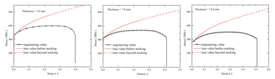
Figure 7.
Stress-strain curves of the plates.
A ductile failure criterion built into the ABAQUS software, which simulated the damage initiation and propagation of the ductile mild steel with acceptable accuracy [12,13], was adopted to simulate failure behavior. In this criterion, damage initiation and evolution were determined by an indicator, which was a function of the equivalent plastic strain and stress triaxiality. Once damage initiation occurred at a certain point, the material stiffness degradation occurred at that point correspondingly. When the stiffness degradation reached a critical value, the material point was assumed to fail, and the corresponding element was deleted. In the low velocity impact scenarios, such as ship collision and falling object impact, the impact velocity was far lower than the wave speed in the mild steel, and the strain rate effect slightly affected the dynamic responses. Thus, the strain rate effect was neglected in the numerical simulation of the impact process [10,14].
4. Results and Discussion
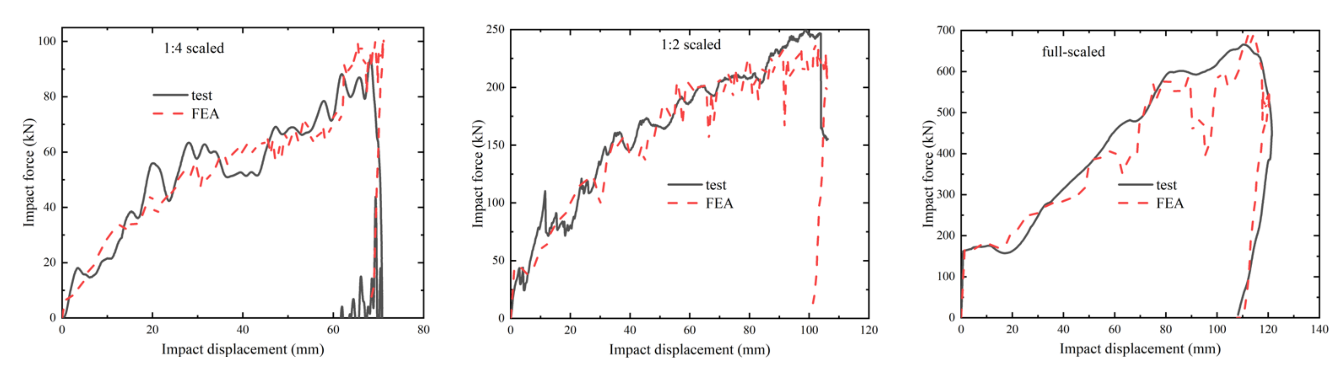
In terms of the impact force response and the deformation mode, the numerical simulation results match well with the experimental results. In both the experimental test and the numerical simulation, the initial impact energy was adjusted by adjusting the mass property and the impact velocity; details were listed in Table 2. As shown in Figure 8 and Figure 9, the plates were torn by the sharp rigid impactor and the deformed shape was similar to the shape of the impactor. Due to the sharp corner of the rigid impactor, firstly, the plates underwent a premature fracture, then were torn with three cracks. Due to the strengthening effect of the stiffener, the damage area was located between two stiffeners next to the impact point, and the stiffeners did not suffer obvious plastic deformation. Figure 10 presents the impact force-displacement curves, and the numerical simulation results match well with the experimental test results. As the impactor fell, the impact force raised rapidly until the premature fracturing of the plate; then, the force raised with the tearing of the plate; at the last step, the impact rebounded due to the elastic energy of the stiffened plate.
Table 2.
Impact velocity and energy in impact test.
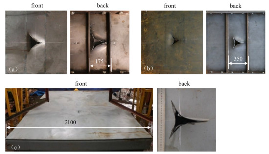
Figure 8.
Damage mode of the three specimens in the impact test (unit: mm): (a) 1:4 scaled; (b) 1:2 scaled; (c) full-scaled.
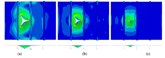
Figure 9.
Damage mode of the three specimens in the numerical simulation: (a) 1:4 scaled; (b) 1:2 scaled; (c) full-scaled.
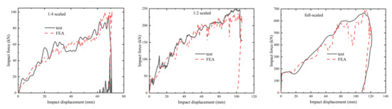
Figure 10.
Comparison of impact force-displacement relationships.
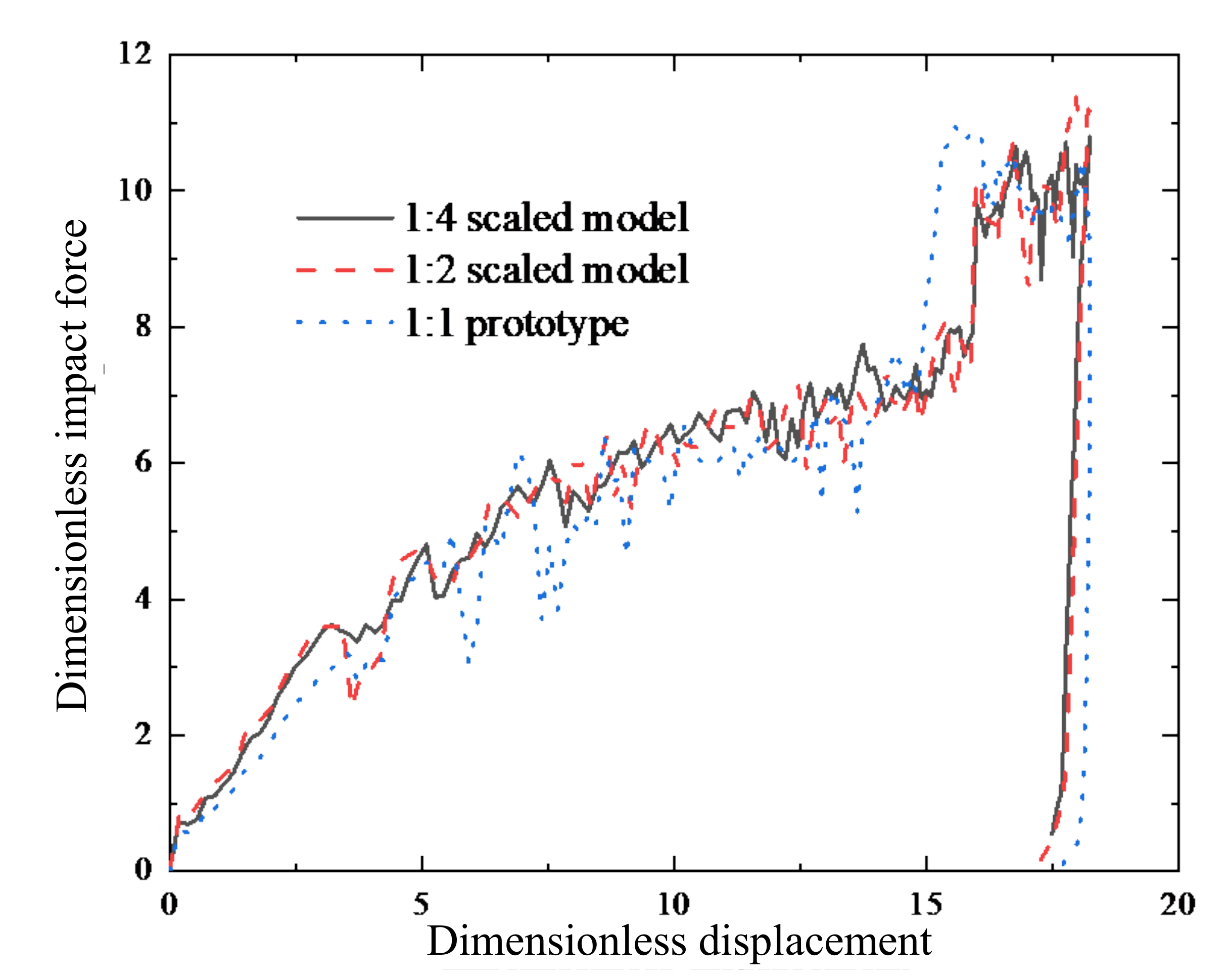
The similarity rules were verified by comparing dimensionless force-displacement relationships of models with different scaling factors. Yield stress, ultimate stress and flow stress of the plates with different thicknesses were listed in Table 3; thus, the curves shown in Figure 10 were converted to non-dimensional forms by the Equation (7), and the non-dimensional curves were shown in Figure 11. Since agreement between the FEA results and the impact test results were achieved in Figure 10, only the simulation results were listed in Figure 11 for the purpose of clear and concise expression. It was shown that the three curves coincide with each other perfectly; the maximum impact displacement and the residual plastic deformation significantly decreased with an increase in the scaling factor. The main reason for the differences was that the 1:2 scaled model and full-scaled prototype underwent a relatively “low energy impact” compared with the 1:4 scaled model. For the 1:4 scaled model, 1:2 scaled model and full-scaled prototype, the initial dimensionless impact energy, which were calculated by Equation (8), were 124.1, 73.7 and 26.4, respectively. The main reason for adopting a relatively “low energy impact” for the 1:2 scaled model and the prototype was that the impact tower cannot withstand such a high energy impact test. For instance, the initial energy should be set to 2.38 MJ for the full-scaled prototype under a dimensionless initial energy of 124.1.
Table 3.
Necessary stress of the materials gained by a tensile test (unit: MPa).
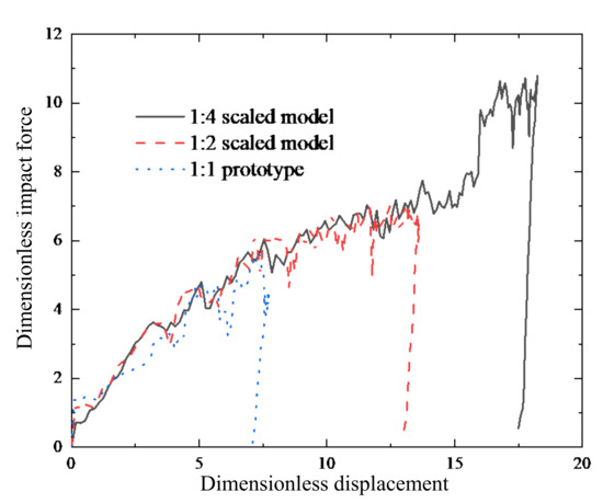
Figure 11.
Comparison of the dimensionless force-displacement curves.
For further investigation, high energy impact scenarios with the same dimensionless initial energy were carried out by the FEA, and agreement was achieved. In the numerical models, the dimensionless initial impact energy was set to 124.1 under the same impact velocity of 5 m/s, which means that the mass property of the impactor was adjusted to fulfill the demands of the initial impact energy. More details in the finite element model were listed in Table 4. The calculated results of dimensionless force-displacement curves were shown in Figure 12; there were slight fluctuations in the curves mainly due to elastic waves in the structure and the element deletion strategy adopted in the finite element model. To avoid unexpected distortion of the elements, the failed elements were deleted during the simulation process. Thus, a slight drop–down of the impact force occurred as soon as an element was deleted. Except for the slight fluctuations, the three curves almost coincided with each other perfectly, which verified the correctness and effectiveness of the similarity laws.
Table 4.
Mass property, impact velocity and energy in finite element analysis.
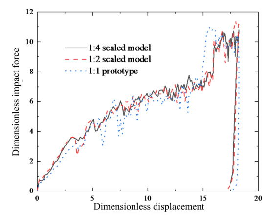
Figure 12.
Comparison of dimensionless force-displacement curves under the same dimensionless impact energy.
5. Conclusions
Similarity laws of scaled models of offshore platform deck structures under low velocity impact of dropping objects were conducted in the present research. The similarity laws of scaled models with different scaling factors were proposed. The dynamic responses of three geometrically similar stiffened structures with scaling factors of 1:4, 1:2, and 1:1 under the dropping impact of a triangular pyramidic impactor were investigated by experimental and numerical methods, and the useful conclusions are listed below:
- (1)
- Similarity laws between scaled models and prototypes of stiffened structures under low velocity impact were established, in forms of dimensionless factors including dimensionless force and displacement, with consideration of flow stress of the different plates.
- (2)
- Finite element results and experimental tests show that the dimensionless force–displacement curves of different models match well, which show the effectiveness of the similarity law.
- (3)
- Stiffened plates of an offshore platform deck would suffer a premature fracture under the impact of a sharp triangular pyramidic impactor; the structure could still withstand impact energy absorption after fracture initiation due to tearing of the plate.
The present research provides useful insight into the similarity laws of dynamic responses of deck structures subjected to falling object impact, and were used in the crashworthiness research of offshore structures.
Author Contributions
Conceptualization, H.Z., J.L.; methodology, Y.H., Y.Z., W.L., J.L.; investigation, R.Y., H.Z.; writing—original draft, R.Y., H.Z.; writing—review and editing, R.Y.; funding acquisition, J.L., R.Y. All authors have read and agreed to the published version of the manuscript.
Funding
This research was funded by the Doctoral Research Start-up Fund of Wuxi Institute of Technology, Grant No. BT2022-03, and National Natural Science Foundation of China, Grant No. 52071150.
Institutional Review Board Statement
Not applicable.
Informed Consent Statement
Not applicable.
Data Availability Statement
The data presented in this study are available upon request from the corresponding author.
Conflicts of Interest
The authors declare no conflict of interest.
References
- Jonas, W.R.; Amdahl, J.; Chen, B.Q. MARSTRUCT benchmark study on nonlinear FE simulation of an experiment of an indenter impact with a ship side-shell structure. Mar. Struct. 2018, 59, 142–157. [Google Scholar]
- Zhang, S.R.; Villavicencio, R.; Pedersen, P.T. Ship collision damages: Case studies. In Developments in the Collision and Grounding of Ships and Offshore Structures; Soares, G., Ed.; Taylor and Francis Group: London, UK, 2020; pp. 17–23. [Google Scholar]
- Gruben, G.; Solvernes, S.; Berstad, T. Low-velocity impact behaviour and failure of stiffened steel plates. Mar. Struct. 2017, 54, 73–91. [Google Scholar] [CrossRef]
- Zhang, M.; Sun, Q.B.; Liu, J.X. A study of the rupture behavior of a ship side plate laterally punched by a full-shape bulbous bow indenter. Ocean Eng. 2019, 182, 48–60. [Google Scholar] [CrossRef]
- Jones, N. Structural Impact; Cambridge University Press: Cambridge, UK, 2011. [Google Scholar]
- Calle, A.G.; Oshiro, R.E.; Alves, M. Ship collision and grounding: Scaled experiments and numerical analysis. Int. J. Impact Eng. 2017, 103, 195–210. [Google Scholar] [CrossRef]
- Zhang, S.M. Plate tearing and bottom damage in ship grounding. Mar. Struct. 2002, 15, 101–117. [Google Scholar] [CrossRef]
- Marinatos, J.N.; Samuelides, M.S. Towards a unified methodology for the simulation of rupture in collision and grounding of ships. Mar. Struct. 2015, 42, 1–32. [Google Scholar] [CrossRef]
- Liu, B.; Villavicencio, R.; Zhang, S. A simple criterion to evaluate the rupture of materials in ship collision simulations. Mar. Struct. 2017, 54, 92–111. [Google Scholar] [CrossRef]
- Cheng, Y.; Liu, K.; Li, Y. Experimental and numerical simulation of dynamic response of U-type corrugated sandwich panels under low-velocity impact. Ocean Eng. 2022, 245, 110492. [Google Scholar] [CrossRef]
- Yun, L. Uniaxial True Stress-Strain after Necking. AMP J. Technol. 1996, 5, 37–48. [Google Scholar]
- Khodadadian, A.; Noii, N.; Parvizi, M.; Abbaszadeh, M.; Wick, T.; Heitzinger, C. A Bayesian estimation method for variational phase-field fracture problems. Comput. Mech. 2020, 66, 827–849. [Google Scholar] [CrossRef] [PubMed]
- Noii, N.; Khodadadian, A.; Ulloa, J. Bayesian inversion for unified ductile phase-field fracture. Comput. Mech. 2021, 68, 943–980. [Google Scholar] [CrossRef]
- Radford, D.D.; Mcshane, G.J.; Deshpande, V.S. Dynamic Compressive Response of Stainless-Steel Square Honeycombs. J. Appl. Mech. 2007, 74, 658–667. [Google Scholar] [CrossRef]


Publisher’s Note: MDPI stays neutral with regard to jurisdictional claims in published maps and institutional affiliations. |
© 2022 by the authors. Licensee MDPI, Basel, Switzerland. This article is an open access article distributed under the terms and conditions of the Creative Commons Attribution (CC BY) license (https://creativecommons.org/licenses/by/4.0/).