Abstract
In plasma MIG welding, inert gas introduced from the torch nozzle is ionized in the upstream region of the MIG arc, which is termed “plasma”. This study aims to clarify the effect of the plasma on the metal-transfer process in the plasma MIG welding through numerical analysis. As a result, the plasma with a temperature of approximately 10,000 K was found to be formed around the wire tip. The MIG arc temperature around the wire tip was 11,000 K at the maximum, which was lower than that of the conventional MIG welding by approximately 1000 K. This difference was caused by the decreased current density around the wire tip due to the influence of the plasma. The droplet temperature was also decreased by 400 K due to this lower current density. The amount of the metal vapor evaporated from the droplet was decreased compared to that of the conventional MIG welding due to the lower droplet temperature. This might lead to a decrease in fume formation generally known in the plasma MIG welding. In the conventional MIG welding, the arc attachment was concentrated around the wire tip, leading to a higher current density. However, in the plasma MIG welding, the plasma transported to the surrounding of the wire tip increases the electric conductivity in that region, due to the influence of the metal vapor mixture. This leads to the dispersion of the arc attachment toward the wire root. Consequently, the current density in the plasma MIG welding was found to decrease compared with that of the conventional MIG welding. The lower current density in plasma MIG welding decreases the Lorenz force acting on the wire neck, thus delaying droplet detachment to make the droplet diameter larger and the metal transfer frequency smaller. The latter was about 20% of that in the conventional MIG welding.
1. Introduction
Plasma Metal Inert Gas (MIG) welding was innovated by Esser et al. in 1972 [1,2], which is a coaxial hybrid welding process combining plasma welding and MIG welding, utilizing the advantages of both welding processes [3]. In the plasma MIG welding, a plasma electrode is installed outside of a MIG contact tip. By using the plasma electrode, inert gas introduce from the torch nozzle is ionized in the upstream region of the MIG arc [4], which is termed “plasma”. Figure 1 shows an example of arc and plasma appearance. The plasma enables to the flexible control the arc shape through the inward Lorenz force produced by the plasma current and self-magnetic field, stabilizing the arc and metal transfer process and minimizing the spatter and fume formation [5]. Furthermore, the plasma with low energy density and large volume can uniformly preheat the base metal surface to a large extent with low heat flux, making it possible to form a high wettability bead [6]. According to these advantages, the plasma MIG welding can be applied for the high-quality welding of various metals such as steel or aluminum [7,8].
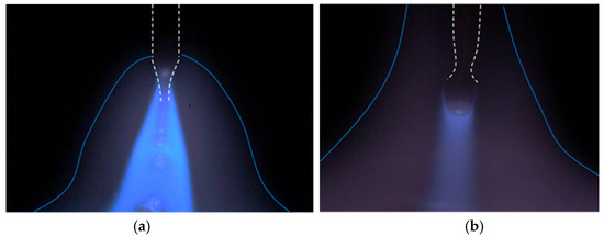
Figure 1.
Arc and plasma appearance in (a) conventional MIG welding and (b) plasma–MIG welding.
In the MIG welding, the welding quality represented by the penetration depth of the base metal and the wettability of the bead is generally known to be strongly governed by the heat input characteristics to the base metal. The heat input to the base metal is mainly produced by the thermal conduction from the arc and the heat content of the metal droplet. Tsujimura et al. reported that the latter occupied approximately 40 percent of the total heat input [9]. The result of calorimetric measurement showed that the iron droplet temperature reached around 3000 K above 250 A [10]. Accordingly, the unstable metal transfer due to the intensive behavior of cathode spots during the conventional MIG welding led to a localized fluctuation of the heat input to the base metal, thus lowering the welding quality.
On the other hand, for the plasma MIG welding, Mamat et al. recently carried out spectroscopic measurements [11] and found that the droplet temperature became 2450 K at 250 A, which was far lower than that in the conventional MIG welding. Moreover, the droplet diameter was larger than that of the conventional MIG welding, so the transition from globular transfer to spray transfer occurred at a higher MIG current. They suggested that the decrease in droplet temperature was due to lower current density caused by the upward expansion of arc attachment around the wire tip, which might be related to the plasma surrounding the wire. Afterward, based on the above finding, Mamat et al. applied the plasma MIG welding to the dissimilar welding of aluminum and steel [12]. Consequently, a sound joint was obtained because of the low droplet temperature and stable metal transfer. However, a mechanism that will cause a decrease in droplet temperature is not yet understood.
The purpose of this study is to clarify effect of plasma on the metal transfer process in the plasma MIG welding through numerical analysis. This paper is divided into four sections. Section 1 introduces the concept of plasma MIG welding and issues regarding droplet temperatures. The simulation model is presented in Section 2, the results and discussion are described in Section 3, and Section 4 summarizes the conclusions of this study.
2. Simulation Model
A numerical simulation of the basic characteristics of the plasma MIG welding was carried out to discuss the influence of the presence of the plasma on the metal transfer process, droplet temperature and arc temperature. For comparison, a conventional MIG welding was also conducted by setting the plasma current at 0.
Figure 2 shows an axisymmetric two-dimensional simulation domain (z, r) with a radius of 15 mm and a height of 30 mm, consisting of an arc region, a wire region, a plasma electrode region and nozzle regions. The regions for feeding the wire, a center gas inlet, a plasma electrode, a plasma gas inlet, shielding gas inlet and nozzles were defined on the top boundary. On the axis, the wire region with a diameter of 1.2 mm and an initial extension of 25 mm, corresponding to an arc length of 5 mm, was defined. The side boundary was a pressure outlet. The bottom boundary corresponded to the surface of the base metal. The region inside the base metal was not calculated. Non-uniform mesh was used; the maximum and minimum sizes were 0.2 mm and 0.05 mm, respectively.
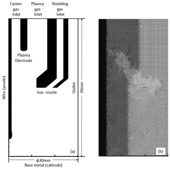
Figure 2.
(a) simulation region and (b) mesh.
Table 1 summarizes the simulation conditions. The wire composition was Fe. The wire feed speed was 5 m/min. The Contact Tip to Work Distance (CTWD) was 30 mm. The plasma electrode diameter is 5 mm. The center gas, the plasma gas, and the shielding gas are pure Ar and introduced from the top boundary at a flow rate of 5, 10 and 10 L/min. The MIG current of DCEP 280 A and the plasma current of DCEP 100 A are given at the top boundary. The plasma current is 0 in case of the conventional MIG welding. The bottom boundary is set to be 0 V.

Table 1.
Simulation conditions.
Distributions of flow velocity, temperature, metal vapor concentration and current density were obtained by solving the time-dependent conservation equations of mass, momentum, energy, mass of metal vapor and current, which are expressed as follows. The magnetic field was obtained from a calculation of vector potential. The plasma was assumed to satisfy the Local Thermodynamic Equilibrium (LTE) condition [13]. The thermodynamic and transport properties of the arc under the LTE condition were calculated as functions of temperature and metal vapor concentration [14]. Fe was assumed to be the metal vapor composition to calculate the above properties. The surface tension coefficient of molten metal of the wire was set as 1.2 N/m, without depending on the temperature. The thermodynamic and transport properties of mild steel were used for the wire [15]. The Volume of Fluid (VOF) method was used to track the free surface. ANSYS Fluent 18.1 was used for the calculation. This model was developed by modifying the MIG welding model, considering the previously reported metal transfer process [16].
Table 2 summarizes boundary conditions. ucenter gas, uplasma gas, ushielding gas and uwf are the velocities corresponding to the center gas flow rate, the plasma gas flow rate, the shielding gas flow rate and the wire feed speed. jMIG and jplasma are the current density corresponding the MIG current and the plasma current. Patm is an atmospheric pressure.
Table 2.
Boundary conditions.
Mass conservation:
Momentum conservation:
Energy conservation:
Mass conservation of metal vapor:
Current conservation:
Ohm’s law:
Vector potential:
Magnetic field:
where mass density, : velocity, p: pressure, : viscus stress tensor, : gravity, : current density, : magnetic field, : a source term for surface tension force, : a source term to express the behavior of the solid region, h: enthalpy, k: thermal conductivity, T: temperature, : electric field, Qr: a source term for arc radiation, Qs: a source term for electron condensation, surface radiation and latent heat of vaporization on the wire surface, Y: mass fraction of metal vapor, D: diffusion coefficient of metal vapor, Mevapmetal: a source term for evaporation of metal, calculated by the Hertz–Knudsen–Langmuir equation, Φ: electric potential, : vector potential.
3. Results and Discussion
Figure 3 shows the temperature distributions immediately after the droplet detachment in the conventional MIG welding and the plasma MIG welding. The temperature distributions present a similar tendency as the arc and plasma appearances shown in Figure 1. Figure 4, Figure 5 and Figure 6 show the distributions of the metal vapor mole fraction, the current density vectors and the current density at the same moment as Figure 3, respectively. In this paper, the numerical analysis results are mainly compared with our experimental results, reported in reference [11]. Even though the welding conditions, such as MIG current and plasma electrode diameter, are different, the tendency of a difference between the conventional MIG welding and plasma MIG welding can be discussed to some extent.
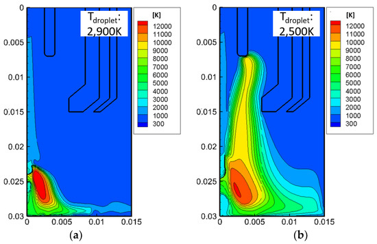
Figure 3.
Temperature distributions in (a) conventional MIG welding and (b) plasma–MIG welding.
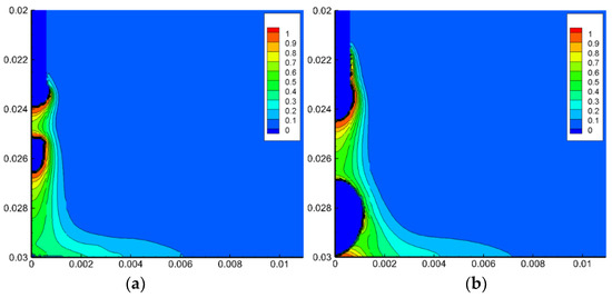
Figure 4.
Metal vapor mole fraction distributions in (a) conventional MIG welding and (b) plasma–MIG welding.
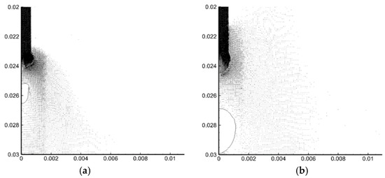
Figure 5.
Current density vectors in (a) conventional MIG welding and (b) plasma–MIG welding.

Figure 6.
Current density distributions in (a) conventional MIG welding and (b) plasma–MIG welding.
In the conventional MIG welding, the arc temperature reached approximately 12,000 K at its maximum. The droplet temperature was raised to approximately 2900 K on average, due to the strong heating cause by the electron condensation and the thermal conduction from the arc plasma. Consequently, a high amount of metal vapor was evaporated from the droplet surface and the wire tip. Then, the metal vapor was transported to the base metal by the plasma jet. Afterward, the metal vapor was radially transported outward. Due to the intensive radiation loss by metal vapor, the arc temperature around the axis decreased to around 6000 K. These results were found to approximately agree with the results of the experimental observation [17].
On the other hand, in the plasma MIG welding, the center gas and shielding gas were ionized in advance in an upstream region of the MIG arc, becoming plasma with a temperature of approximately 10,000 K. The arc temperature around the wire tip was lower than that of the conventional MIG welding by approximately 1000 K. The tendency for the arc temperature to decrease agrees with the spectroscopic measurement result in reference [11]. This difference indicates the decreased current density around the wire tip by influence of the plasma. The droplet temperature was decreased to 2500 K, which might be due to this lower current density. Mamat et al. reported that the droplet temperature in plasma MGI welding using a plasma electrode with a diameter of 3 mm decreased by more than 300 K compared with that of conventional MIG welding at an MIG current of 250 A [11]. The amount of metal vapor that evaporated from the droplet was decreased compared to that of the conventional MIG welding due to the lower droplet temperature. This will lead a lower amount of fume formation than is generally found in plasma MIG welding. The metal transfer frequency was about 11.5 Hz, which was smaller than 53.3 Hz in the conventional MIG welding.
In the conventional MIG welding, the arc attachment was concentrated around the wire tip, leading to a higher current density. However, in the plasma MIG welding, the plasma transported to the surrounding wire tip increases the electric conductivity in that region, which is also due to the influence of the metal vapor mixture, as shown in Figure 7. This leads to dispersion of the arc attachment toward the wire root. Consequently, the current density in the plasma MIG welding was found to decrease compared with that of the conventional MIG welding. The lower current density in plasma MIG welding decreases the Lorenz force acting on the wire neck, thus delaying droplet detachment to make the droplet diameter larger and the metal transfer frequency smaller than those in the conventional MIG welding.
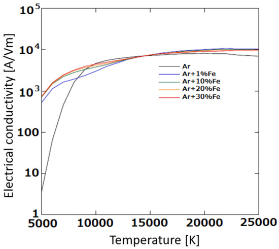
Figure 7.
Dependence of electrical conductivity on temperature and metal vapor concentration.
The tendency of differences in arc characteristics and the metal transfer process between conventional MIG welding and plasma MIG welding, obtained through the numerical analysis, agreed with that observed in the experiment [11].
4. Conclusions
In this study, a numerical analysis of basic characteristics of the plasma MIG welding was carried out, especially focusing on the plasma’s influence on the metal transfer process. The main conclusions are summarized as follows:
- In plasma MIG welding, the center gas and shielding gas are ionized in advance in an upstream region of the MIG arc, becoming plasma with a temperature of approximately 10,000 K.
- The MIG arc temperature around the wire tip was 11,000 K at its maximum, which was lower than that of the conventional MIG welding by approximately 1000 K.
- In plasma–MIG welding, the droplet temperature is lower than that of the conventional MIG welding by 400 K, decreasing the amount of metal vapor that evaporated from the droplet.
- The plasma transported to the surrounding of the wire tip increases the electric conductivity in that region. This leads to dispersion of the arc attachment toward the wire root.
- The current density in the plasma MIG welding is found to decrease compared with that of the conventional MIG welding, thereby causing decrease in the droplet temperature and metal transfer frequency. The latter was about 20% of that in the conventional MIG welding.
In this study, only the case using mild steel as the wire material was discussed. However, phenomena such as a decrease in the droplet temperature and metal transfer frequency might generally occur in plasma–MIG welding regardless of the wire materials, because it is related to the thermodynamic and transport properties of the gas rather than those of the wire material.
It is considered that understanding the mechanism used to govern the metal transfer process strongly contributes not only to improving the quality of plasma–MIG welding but also to propose an innovative welding process, which enables flexible control of the metal transfer process.
Author Contributions
Conceptualization, methodology, simulation, writing, supervision, S.T.; discussion, S.T., S.B.M., A.B.M., T.Y. and M.T. All authors have read and agreed to the published version of the manuscript.
Funding
This research received no external funding.
Institutional Review Board Statement
Not applicable.
Informed Consent Statement
Not applicable.
Data Availability Statement
Data are available based on the requirements to verify this work.
Conflicts of Interest
The authors declare no conflict of interest.
References
- Essers, W.G. New process combines plasma with GMA welding. Weld. J. 1976, 55, 394–400. [Google Scholar]
- Essers, W.G.; Jelmorini, G.; Tichelaar, G.W. The plasma-MIG welding process. Tool Alloy Steels 1978, 12, 275–277. [Google Scholar]
- Resende, A.A.; Ferraresi, V.A.; Scotti, A.; Dutra, J.C. Influence of welding current in plasma–MIG weld process on the bead weld geometry and wire fusion rate. Weld. Int. 2011, 25, 910–916. [Google Scholar] [CrossRef]
- Tanaka, M.; Tamaki, T.; Tashiro, S.; Nakata, K.; Ohnawa, T.; Ueyama, T. Characteristics of ionized gas metal arc processing. Surf. Coat. Technol. 2008, 202, 5251–5254. [Google Scholar] [CrossRef]
- Ono, K.; Liu, Z.; Era, T.; Uezono, T.; Ueyama, T.; Tanaka, T.; Nakata, K. Development of plasma MIG welding system for aluminum. J. Light Met. Weld. Constr. 2008, 46, 501–505. [Google Scholar]
- Katayama, T.; Tashiro, S.; Tanaka, M. Improvement of bead formation of plasma MIG welding in pure argon atmosphere. Q. J. Jpn. Weld. Soc. 2011, 29, 39s–42s. [Google Scholar] [CrossRef][Green Version]
- Mamat, S.; Sidek, N.A.; Apandi, N.A.A.M.; Roslan, R.A.E.; Ter, T.P.; Yuji, T.; Tashiro, S.; Tanaka, M. Observation of Microstructure and Mechanical Properties in Heat Affected Zone of as-welded Carbon Steel by using Plasma MIG welding Process. Metals 2022, 12, 315. [Google Scholar] [CrossRef]
- Cai, D.; Han, S.; Zheng, S.; Luo, Z.; Zhang, Y.; Wang, K. Microstructure and corrosion resistance of Al5083 alloy hybrid plasma-MIG welds. J. Mater. Processing Tech. 2018, 255, 530–535. [Google Scholar] [CrossRef]
- Tsujimura, Y.; Tanaka, M. Numerical Simulation of heat source property with metal vapor behavior in GMA Welding. Q. J. Jpn. Weld. Soc. 2012, 30, 68–76. [Google Scholar] [CrossRef]
- Soderstrom, E.J.; Scott, K.M.; Mendez, P.F. Calorimetric Measurement of Droplet Temperature in GMAW. Weld. J. 2011, 90, 77S–84S. [Google Scholar]
- Mamat, S.B.; Tashiro, S.; Tanaka, M.; Yusoff, M. Study on factors affecting the droplet temperature in plasma MIG welding process. J. Phys. D Appl. Phys. 2018, 51, 135206. [Google Scholar] [CrossRef]
- Mamat, S.B.; Tashiro, S.; Masri, M.N.; Hong, S.M.; Bang, H.S.; Tanaka, M. Application of pulse plasma MIG welding process to Al/steel dissimilar joining. Weld. World 2020, 64, 857–871. [Google Scholar] [CrossRef]
- Boulos, M.I.; Fauchais, P.; Pfender, E. Thermal Plasmas: Fundamentals and Applications; Springer: New York, NY, USA, 1994; pp. 4–5. [Google Scholar]
- Murphy, A.B.; Arundell, C.J. Transport coefficients of argon, nitrogen, oxygen, argon-nitrogen and argon-oxygen plasmas. Plasma Chem. Plasma Process. 1994, 14, 451–490. [Google Scholar] [CrossRef]
- Hertel, M.; Spille-Kohoff, A.; Fussel, U.; Schnick, M. Numerical simulation of droplet detachment in pulsed gas–metal arc welding including the influence of metal vapour. J. Phys. D Appl. Phys. 2013, 46, 224003. [Google Scholar] [CrossRef]
- Tashiro, S.; Murphy, A.B.; Tanaka, M. Numerical simulation of fume formation process in GMA welding. Weld. World 2018, 62, 1332–1338. [Google Scholar] [CrossRef]
- Rouffet, M.E.; Wendt, M.; Goett, G.; Kozakov, R.; Schoepp, H.; Weltmann, K.D.; Uhrlandt, D. Spectroscopic investigation of the high-current phase of a pulsed GMAW process. J. Phys. D Appl. Phys. 2010, 43, 434003. [Google Scholar] [CrossRef]


Publisher’s Note: MDPI stays neutral with regard to jurisdictional claims in published maps and institutional affiliations. |
© 2022 by the authors. Licensee MDPI, Basel, Switzerland. This article is an open access article distributed under the terms and conditions of the Creative Commons Attribution (CC BY) license (https://creativecommons.org/licenses/by/4.0/).