Abstract
Precipitation of MnS inclusions in steel affects the mechanical properties of the material significantly. The evolution of MnS inclusions along the continuous casting slab thickness and its influencing factors has not been clearly established and comprehensively studied. In this paper, solidification macrostructure, sulfur segregation and MnS inclusions in the continuous casting slab of medium carbon structural steel 45# were studied by various methods, including the metallographic observations, elemental analysis, scanning electron microscope (SEM) with Energy Dispersive Spectrometer (EDS) observation, automatic particle analysis, and thermodynamic calculations. The 2D/3D morphologies of MnS inclusions suggest that the sulfides turn from globular to rodlike, and further to dendritic shape along the slab thickness progressively. Furthermore, it was found that MnS inclusions are remarkably aggregated in the columnar crystals and the equiaxed crystals mixed zone, where the sulfides have the largest average diameter of 6.35 μm and the second maximum area fraction of 0.025% along the slab thickness. In order to reveal the mechanism of this phenomenon, the precipitation temperature of MnS inclusion in the 45# steel was clarified by thermodynamic calculation and experimental observation, and the quantitative relationships among the distribution of sulfur content, secondary dendrite arm spacing (SDAS), and precipitation area fraction of MnS inclusions were discussed. Moreover, the inclusion size was numerically predicted to compare with the measured value. The results indicate that the large SDAS, high sulfur content and low cooling rate accounting for the large-size aggregated MnS inclusions in the mixed zone. Unfortunately, the dendritic MnS inclusions, even if the average diameter exceeds 52 μm, can act as the nucleation sites for ferrites, and the distribution of the sulfides promotes uneven microstructure in the steel.
1. Introduction
Non-metallic inclusions in steels usually have a detrimental effect on the material performance. With the improvement of the quality requirements of steel products, the control of inclusions has been a long-term problem during the steelmaking process. Manganese sulfide, as one of the typical inclusions in steels, is beneficial in improving machinability of free-cutting steels [1,2], as well as slowing grain growth [3] and promoting the precipitation of intragranular ferrite [4]. On the other hand, the material properties in the transversal direction are weakened due to the anisotropy caused by the elongation of MnS inclusions during hot rolling [5]. Different steels have different requirements for the morphology and distribution of MnS inclusions. Therefore, many studies on the formation and control of MnS inclusions have been carried out through the years [6,7,8].
According to the classical work by Yoichi [9] and Oikawa et al. [10], the morphologies of MnS inclusions were classified into three broad categories: (1) randomly dispersed globular sulfides (Type I) resulting from metastable monotectic reaction, (2) the product of stable eutectic reaction, rodlike or dendritic sulfides (Type II), (3) angular sulfides (Type III) formed by pseudo-eutectic reaction. Type II sulfides with good deformability are being regarded as the most harmful type, as they can be deformed into large-size strips during hot rolling [1].
The morphology, size and distribution of MnS inclusions vary with steel composition and process conditions. For instance, Takada et al. [11] suggested that Type I sulfides were observed in the steels with sulfur contents less than 0.01%, while Type II sulfides were found in the steels containing sulfur more than 0.05% or more. The starting temperature of MnS precipitation was strongly correlated with sulfur content during or after the solidification of the steels [12]. Ishida et al. [7] reported that with the increase in silicon, aluminum and titanium content, the morphology of MnS inclusions would turn from spherical to dendritic, and further to irregular shape. Furthermore, calcium, rare earths, etc. were utilized to promote the formation of fine sulfides which are more stable and have a higher melting point than that of manganese sulfides [13,14,15]. Imagumbai et al. [16] proposed that the quantity of MnS inclusions increased with the increase in cooling rate, while the average size decreased. Moreover, the quantity and volume fraction of Type II sulfides increased with the cooling rate in the range of 0.14 to 2.2 °C/min, and the Type I and Type III sulfides increased in quantity accompanied by the decrease in volume fraction as the size reduced [17].
During the continuous casting process of steel, the solidification macrostructure provides a key link to the distribution of composition and cooling rate along the continuous casting slab thickness. As mentioned above, it will affect the precipitation and growth of MnS inclusions. Steady-state unidirectional solidification models have been suggested to study the effect of solidification structure on sulfide inclusions; however, it is in the size of dendrite structures instead of the macrostructure of the slab [16,17]. For the connection between macrostructure and sulfur content distribution in the slab, the studies mainly focus on the mechanism of center segregation [18,19]. The relationship between the size of Type II sulfides and solidification variables in steels with different sulfur contents was empirical and proposed by Takada et al. [11]. Ueshima et al. [20] simplified the dendrite morphology to predict the precipitation of MnS during solidification of low carbon steels. Generally, a great deal of work has been conducted to study the evolution of MnS inclusions during solidification based on empirical [11,21] or semi empirical models [1,7]. However, the quantitative relationship among solidification macrostructure, segregation of sulfur, and evolution of morphology, size of MnS inclusions along the continuous casting slab thickness has not been clearly established and comprehensively studied.
Medium carbon structural steels have been used for a multitude of components such as gears, shafting which require great strength, and other heavy duty products [22,23]. MnS inclusion is one of the main factors that notably affects the internal and surface quality of the steel products. In the present study, the variation of MnS inclusions along the thickness of slab together with the solidification macrostructure of medium carbon structural steel 45# was discussed to elucidate the effect of cast features on the MnS inclusion. It was found that MnS inclusions aggregated significantly in the mixed zone, and the mechanism of the aggregation was clarified by the thermodynamic calculation and experimental results. In addition, the influence of large-size MnS inclusions on the microstructure and cracks was also analyzed.
2. Materials and Methods
In this study, the medium carbon structural steel 45# was produced by a vertical bending continuous caster in a Chinese steel plant; the chemical compositions of the steel are listed in Table 1. In order to avoid the deviation caused by fluctuation during casting process, a slab sample with 120 mm length was collected under the steady state casting conditions. The details of the casting parameters during sampling are given in Table 2. The slab sample was cut into three pieces for different tests as shown in Figure 1, including the analysis of inclusions, microstructure, element segregation, and macrostructure.

Table 1.
Chemical composition of continuous casting slab of 45# medium carbon structural steel.
Table 2.
The continuous casting process parameters used during sampling.
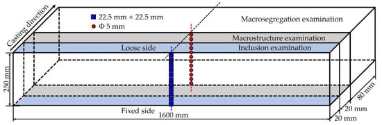
Figure 1.
Sampling schemes for various examinations.
To evaluate the behavior of inclusions in many aspects, one piece of the slab sample was cut into specimens with size of 22.5 mm × 22.5 mm along slab thickness from the loose side to the fixed side. Firstly, the morphology, size and quantity of inclusions were analyzed by using automatic particle analysis system after the specimens were roughly ground and finely polished. Secondly, the specimens were etched with 4% nitric acid alcohol solution at 25 °C for about 12 s to discuss the relationship between microstructure and inclusions by optical microscope (Shanghai optical instrument factory, Shanghai, Chia) and SEM-EDS (Zeiss, Oberkochen, Germany) observation. Finally, in order to reveal the pattern of MnS inclusions more accurately, the specimens were etched with a non-aqueous solution electrolysis method to obtain the three-dimensional morphology of the inclusions. The electrolyte used is an organic solution with anhydrous methanol as the solvent, which consists of 1% tetramethylammonium chloride, 5% triethanolamine, 5% glycerol and 89% methanol. The electrolysis device and process were described in details by Ren et al. [24]. The electrolysis time was limited to about 10 min to maintain the original appearance of specimens as complete as possible and prevent inclusions from falling off the surface of the specimens.
To reveal the solidification macrostructure of the slab, another piece was cut into specimens with size of 250 mm × 300 mm along slab width for macroetching. After surface grinding, the specimen was etched with hydrochloric acid–water solution with a volume ratio of 1:1 at 80 °C for about 60 min. During the whole etching process, it was ensured that the etching surface of the specimen completely entered the solution. The specimen was washed with boiled water and alcohol as the etching was completed. Then, the image of the etched surface was collected by a scanner after it was dried. Finally, the macrostructure of the slab was analyzed, including the chill zone, columnar zone, mixed zone, equiaxed zone and secondary dendrite arm spacing, etc.
The main methods to analyze the macrosegregation in continuous casting slab are infrared absorption method and sulfur printing, etc. The former was adopted to discuss the macrosegregation along the slab thickness direction of the studied steel due to the low sulfur content. The segregation analysis specimens were collected by drilling on the third piece at the positions corresponding to the inclusion analysis specimens as shown in Figure 1. The weight of steel chips obtained at each position exceeded 5 g. Additionally, the sulfur contents of the specimens were tested by a carbon–sulfur analyzer.
3. Results
3.1. Solidification Macrostructure
During the solidification in the continuous casting process, the dendritic growth essentially affects the formation and evolution of sulfide inclusions due to the unevenness of composition distribution and the difference of cooling rate along the slab thickness [5,6,25]. In order to analyze the relationship between MnS inclusions behavior and cast features, the macrostructure of continuous casting slab of medium carbon structural steel 45# was obtained by macroetching methods. Details of different solidification zones from the loose side to the fixed side of the slab are shown in Figure 2, including the chill zone, columnar zone, mixed zone and equiaxed zone. In the initial stage of the casting, there is a great degree of supercooling in the molten steel due to the high-intensity cooling from the mold wall. The high undercooling promotes the heterogeneous nucleation of a large number of randomly oriented fine crystal grains, forming the surface chilled layer shown in Figure 2a. As the solidification continues, the crystal growth parallel to slab surface is suppressed, causing the directional solidification of the molten steel to the slab center. Then, the dendritic layer extending perpendicular to the slab surface is formed as shown in Figure 2b, which is called the columnar zone. The enrichment of solute atoms in the liquid phase increased with the development of columnar crystals, which gradually increases the undercooling of the components at the solidification front. When the constitutional supercooling is large enough for crystal nucleation, the columnar-to-equiaxed transition (CET) occurs, and then develops into the equiaxed zone (Figure 2d) in the slab center. However, CET usually acts gradually, and therefore a mixed zone is formed between the columnar zone and equiaxed zone, where columnar crystals and equiaxed crystals coexist. As shown in Figure 2c, the crystal growth in the mixed zone is chaotic, but directs to the center of the slab in general. Thicknesses of each solidification zone in the transverse section of the slab were measured and the measurements are described in Table 3.
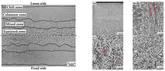
Figure 2.
Macrostructure of the partial slab transverse section of medium carbon structural steel 45#. (a) Chill zone, (b) columnar zone, (c) mixed zone and (d) equiaxed zone.
Table 3.
Thickness of different solidification zones in the transverse section of the slab.
The thickness of the chill zone near the loose side is basically the same as that near the fixed side, and so is the columnar zone. The chill layer is the thinnest, with the total thickness of the upper and lower parts of 14.87 mm. While the columnar zone reaches the maximum thickness of 112.39 mm. The values for mixed zone and equiaxed zone are 54.09 mm, 68.65 mm, respectively. There exists significant difference between the upper and lower equiaxed zones, as the thickness of the former is 6.41 mm smaller than that of the latter. This probably arises from that part of the upper side dendrites fused to act the nucleation sites of the lower side crystals, which speeds up the formation of equiaxed zone near the fixed side.
3.2. Morphology and Distribution of MnS Inclusions
According to the analysis results of SEM-EDS, it can be predicted that the inclusions in the slab of medium carbon structural steel 45# are mainly Al2O3-SiO2-CaO-MnS. Based on the different contents of oxygen and sulfur, they can be simply divided into three categories: oxides, sulfides and their compounds. According to morphological observation and EDS analysis results, the inclusion with the sum of manganese and sulfur content exceeding 95 wt pct is defined as pure MnS. The statistical results of automatic particle analysis data indicate that the quantity and area fraction of MnS in 45# steel slab account for as high as 47.5% and 55.7% of the total inclusions, respectively, which would have a significant impact on the production process and final service performance. The typical 2D and 3D morphologies of MnS inclusions observed in the slab of the 45# steel are shown in Figure 3. The measured results of average diameter, quantity density and area fraction of MnS inclusions along the slab thickness from the loose side to the fixed side are shown in Figure 4.
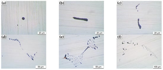
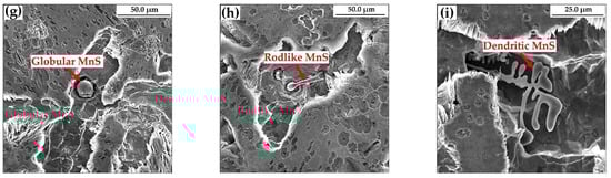
Figure 3.
Typical 2D and 3D morphologies of MnS inclusions in the slab of medium carbon structural steel 45#. (a–f) 2D morphologies, (g–i) 3D morphologies.
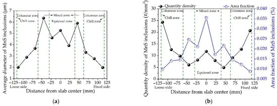
Figure 4.
Distribution of MnS inclusions along the slab thickness of medium carbon structural steel 45#: (a) average diameter, (b) quantity density and area fraction.
There are considerable differences in the morphology of MnS inclusions examined in the studied 45# steel slab. Figure 3a,g shows the typical randomly dispersed globular MnS (Type I) which was mainly observed at the edge of the slab. The sizes of the spherical MnS inclusions are significantly smaller than the others found in the remaining area of the slab. It is shown in Figure 4a,b that the quantity density of MnS inclusions in the slab edge samples are the largest but minimum in average diameter due to the dominance of spherical MnS in this area. This can be explained by that the cooling rate of slab edge is the greatest during the continuous casting process. The greater the cooling rate, the larger the degree of supercooling [26]. The large supercooling caused by the high cooling rate will promote the nucleation of MnS inclusions, resulting in a large number of fine globular MnS. That is, the cooling rate plays a critical role in the size and quantity of Type I MnS inclusion, which is consistent with the previous studies [27,28,29]. In addition to globular MnS, rodlike MnS (Figure 3b,c,h) and dendritic MnS (Figure 3d–f,i) classified as Type II were also observed. The former is mainly distributed in the columnar zone of the slab, and the latter is presented in the mixed zone and equiaxed zone. Takada et al. [11,17] suggested that the transition of MnS inclusion from Type I to Type II occurred when the sulfur content exceeded 0.05%. Imagumbai [16] and Olkawa et al. [7] also found the Type II MnS inclusions in steels with a sulfur content of 0.073% and 0.3%, respectively. However, a great amount of Type II MnS inclusions was observed in the studied steel with the sulfur content far less than 0.05%. The reasonable explanation is that the solidification cooling rate inside the thick slab is quite small, which gives MnS inclusions sufficient time to grow up and finally transform to dendritic shapes. Therefore, the cooling rate is also one of the main factors affecting the growth of Type II MnS inclusion.
During the continuous casting process, the cooling rate along the slab thickness direction varies greatly, accompanied by the different growth behavior of MnS inclusions. As shown in Figure 4, the diameter and area fraction of inclusions gradually increase from the slab edge to the mixed zone, while the quantity density decreases accordingly, and they all reach the peak in the mixed zone. The average diameter of MnS inclusions presents the maximum value of 6.35 μm in the mixed zone near the loose side, which is 2.47 μm larger than that in the entire slab thickness. Moreover, the area fraction of MnS inclusions in the same position is 0.025%, which is the second maximum value. In the equiaxed zone, the average diameter, quantity density and area fraction of MnS inclusions increase as the distance from the center of slab decreases. The area fraction of MnS inclusions has the maximum value of 0.036% in the slab center, while the average value along the slab thickness is 0.018%.
MnS inclusions have good deformation ability and can be deformed into long strips during steel rolling, which will make the mechanical properties of steel anisotropic [30,31]. In addition, the elongated MnS inclusions are likely to act as the nucleation sites and expansion channels of cracks, thereby reducing the mechanical properties of steel [32]. Larger MnS inclusions usually have a detrimental effect on the mechanical properties of steel. Therefore, the distribution of large-size MnS inclusions along the slab thickness of the 45# steel was analyzed, including the quantity density of MnS inclusions with diameter larger than 10 μm or area greater than 50 μm2 as shown in Figure 5. The MnS inclusions with large diameter or area are distributed similarly in the slab. In general, both of their quantities gradually increase along the slab thickness toward the center. In particular, the quantity density of large-diameter and large-area MnS inclusions in the mixed zone near the loose side are 0.70/mm2 and 1.67/mm2, respectively, while in the slab center they are 0.16/mm2 and 0.68/mm2, and the average values are 0.17/mm2 and 0.56/mm2. That is, there are much more large-size MnS inclusions in the mixed zone than in the other positions of the slab. Therefore, the aggregation of MnS inclusions is detected in the mixed zone of the slab. The typical morphologies of MnS inclusions aggregation in the slab of the 45# steel is shown in Figure 6. The types of aggregated MnS inclusions are mainly dendritic, with a small amount in flakes and angular shapes, and the size can be as large as 120 μm. These inclusions could be deformed into long strips in the subsequent rolling process, which are harmful to the steel products.
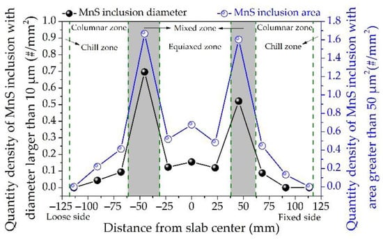
Figure 5.
Distribution of large-size MnS inclusions along the slab thickness of medium carbon structural steel 45#.
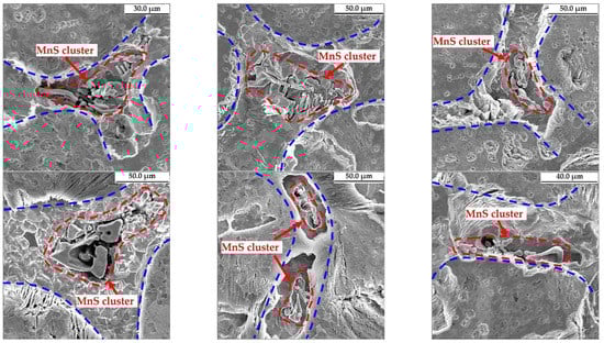
Figure 6.
Typical morphologies of MnS inclusions aggregation in the slab of medium carbon structural steel 45#.
4. Discussion
4.1. Precipitation Behavior of MnS Inclusion
MnS inclusions may precipitate during or after solidification of molten steel [8,10,33]. In order to accurately analyze the precipitation behavior of MnS inclusion in the 45# steel, the formation temperature of the MnS inclusion, liquidus and solidus temperature of the steel were calculated to determine the specific precipitation stage of MnS inclusion during continuous casting process. The calculated results are verified by experimental observations. The following equation formulates the principle of chemical reaction during the formation of MnS inclusion.
where KMnS is the equilibrium constant of reaction (1), and the corresponding equilibrium solubility products for MnS in liquid and γ-iron phase are presented in Table 4. aMnS, a[Mn] and a[S] are the activity of MnS, Mn and S, respectively; aMnS is taken as one for the formed pure MnS; fn is the activity coefficient of the solute element n, which is calculated by Equations (3) and (4) [34]; w[Mn], w[S], w[n] and w[m] are the mass fractions of solute elements Mn, S, n and m; is the interaction coefficient of element m to n, which is given in Table 5. The liquidus and solidus temperature of the 45# steel are 1766 K and 1642 K, respectively, which were calculated by Equations (5) and (6) [1].
[Mn] + [S] = MnS(s)
Table 4.
Solubility products for MnS in different phases.
Table 5.
Interaction coefficients of different elements in molten steel at 1873 K [6,35].
The calculated equilibrium relationship between w[Mn] and w[S] in the liquid and γ-iron phase of the 45# steel is shown in Figure 7a, as well as the equilibrium solubility product of w[Mn]·w[S] at different temperatures in Figure 7b. It is suggested that the content of the studied steel is located between the equilibrium lines of liquid phase and solid γ-iron phase, and the precipitation of MnS inclusion initiates between 1766 K and 1642 K. Therefore, the MnS inclusion in the slab of the 45# steel is formed during the solidification of molten steel. The relationship between MnS inclusions and solidification structure was revealed by experimental observation as shown in Figure 8. Figure 8a indicates the microstructure of the 45# steel slab with a dendrite shape. Figure 8b is the details of Figure 8a with enlarged scale. The distribution of MnS inclusions with EDS analysis is shown in Figure 8c–e. A large amount of MnS inclusions lies between the dendritic microstructure. Figure 8f identifies the MnS inclusion formed between the original dendrites in the 45# steel slab sample without etching or electrolytic treatment. Similarly, Figure 6 also clarifies that most of the aggregated MnS inclusions obtained from the slab samples after electrolysis are also distributed between the dendrites.
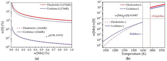
Figure 7.
Thermodynamic calculation results of MnS inclusion formation in the medium carbon structural steel 45#. (a) Phase stability diagram of MnS, (b) equilibrium solubility product of MnS.
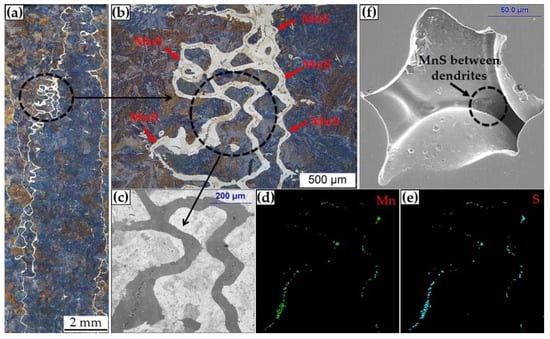
Figure 8.
Relationship between MnS inclusions and solidification structure in the slab of medium carbon structural steel 45# revealed by experimental observation. (a,b) microstructure, (c–e) element mapping results, (f) MnS inclusion observed between dendrites.
The calculations and experimental observations together prove that MnS inclusion in the studied 45# steel is formed in the residual liquid between dendrites at the end of solidification.
4.2. Mechanism of MnS Inclusion Aggregation
The precipitation of MnS inclusions at the end of solidification is heavily dependent on the local sulfur content in the residual liquid and the secondary dendrite arm spacing in different macrostructure zones. Therefore, the sulfur content and secondary dendrite arm spacing along the slab thickness of the 45# steel were measured. The comparison between the measurement results and the area fraction of MnS inclusions is shown in Figure 9. Where Slocal/Saverage presents the segregation index of sulfur.
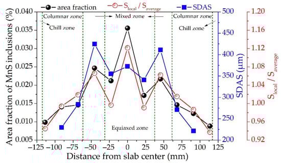
Figure 9.
Distribution of MnS inclusions, sulfur segregation, and secondary dendrite arm spacings along the slab thickness of the medium carbon structural steel 45#.
The mixed zone is the key transformation region for not only the segregation index of sulfur, but also the secondary dendrite spacing, and the area fraction of MnS inclusions. Generally, the segregation of sulfur gradually increases from negative to positive segregation along the slab thickness toward the center. The positive segregation index has the maximum value of 1.12 occurs in the slab center, and the second maximum value is 1.06 in the mixed zone near the loose side. In addition, there is a certain degree of negative segregation between the mixed zone and slab center. This is because the dendritic bridge formed in the mixed zone can hinder the flow of solute-rich liquid and promote enrichment and dilution of solute elements in the upper and lower parts of the dendritic bridge, resulting in corresponding positive and negative segregation, respectively [36]. In particular, the evolution trend of sulfur segregation is largely consistent with the area fraction of MnS inclusions along the slab thickness. This indicates that the variation of sulfur content along the slab thickness probably responds for one of the main factors affecting the aggregation of MnS inclusions in the mixed zone, as the amount of type II MnS inclusion increases with the sulfur content in steel [9].
The SDAS along the slab thickness was tested by the line intercept method [37], excluding those in the areas near the slab surface where the secondary dendrites are unidentifiable. Similarly, the SDAS increases gradually along the slab thickness toward the center in general. However, it dramatically reaches the peak in the mixed zone, which is consistent with the previously reported experimental results [38,39]. The local solidification time of molten steel in the mixed zone is greatly increased for the existence of settling equiaxed grains which hinders the growth of columnar tip, as well as the decreasing in the driving force for solidification caused by an above-average increase in the solute concentration in the liquid [40]. Hence, longer solidification time promotes the formation of larger SDAS [41]. As stated above, the MnS inclusions are formed in the residual liquid between dendrites at the end of solidification. Coarser dendrites with larger SDAS will provide better conditions for the formation and growth of MnS inclusions.
Moreover, the size of MnS inclusion also plays a crucial role in its distribution. Therefore, the distribution of MnS inclusion diameter was calculated. Equation (7) presents the calculation model suggested by Bleck et al. [1]. The cooling rate during solidification dT/dt, also the manganese and sulfur content as well as the SDAS λ2 were taken into account. The constant K turned out to be 0.85 for the studied 45# steel which solidifies with a primary delta-ferrite.
The measured sulfur content and SDAS along the slab thickness, as shown in Figure 9, were adopted as input data in the calculation. The effect of slightly varies in Mn content were ignored. A heat transfer model was applied to predict the variation of cooling rate during solidification, more details could be found elsewhere in the authors’ previous research [42,43].
The heat transfer during the slab continuous casting process is governed by Equation (8).
where T is the temperature (K), t is the casting time (S), x, y are the coordinates along slab width and thickness, respectively (m); for thermophysical parameters at different temperatures, ρT is the density of steel (kg/m3), Cp,T is the specific heat (J/kg·K), and kT is the thermal conductivity (W/m·K).
The slab cooling during the continuous casting process is mainly composed of two parts, namely the cooling in the mold and the secondary cooling after the slab leaves the mold. The heat transfer boundary conditions in the mold were expressed in Equation (9) [42].
where qm is the heat flux at the mold wall (W/m2), A and B are constants, z is the instant length of casting (m), and Vc is the casting speed (m/s).
In the secondary cooling section, the primary solidified shell was subjected to four different types of cooling, i.e., water spray cooling, water evaporation cooling, radiation cooling, and roll contact cooling. Accordingly, the heat transfer conditions were quite different, which has been discussed elsewhere [42]. The secondary cooling section was subdivided into eight cooling zones for operation and maintenance. The length and water flow rate for different cooling zones are listed in Table 6.
Table 6.
Length and water flow rate for different secondary cooling zones used in the calculation.
Comparison between the calculated and measured diameter of MnS inclusions, as well as the calculated cooling rate along the slab thickness of the 45# steel, are displayed in Figure 10. In the columnar zone, the diameter of MnS inclusion is negatively correlated with the cooling rate, that is, the inclusion size gradually increases with the decrease in the cooling rate. In the mixed and equiaxed zone, the influence of cooling rate on the MnS inclusion size is weakened, while the sulfur content and SDAS play a crucial role in the growth. The evolution trend of the calculated diameter of MnS inclusion is in good agreement with the measured data. The inclusion size increases gradually along the slab thickness toward the center but reaches the maximum in the mixed zone. Large-sized MnS inclusions are more likely to aggregate to have a destructive impact on the performance of the steel. For instance, Yang et al. [44] proposed that micro-cracks occurred in the thickness center of rolling samples were mainly caused by MnS inclusions larger than 10 μm. Wang et al. [45] reported that MnS inclusions with a size of about 20 μm distributed in segregation regions exaggerate the extent of the band microstructure. The calculated value at almost every position is smaller than the measured one, especially in the mixed zone, which may be caused by the gathered inclusions identified as a single inclusion during the detection process, resulting in the dimensional differences.
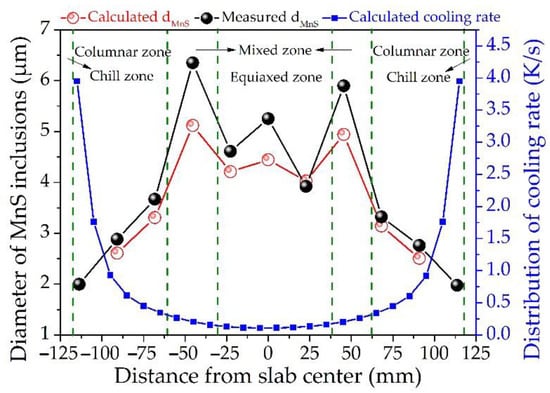
Figure 10.
Distribution of the calculated and measured diameters of MnS inclusions, calculated cooling rate along the slab thickness of the medium carbon structural steel 45#.
In summary, the evolution mechanism of MnS inclusion along the slab thickness of the 45# steel can be described as shown in Figure 11.
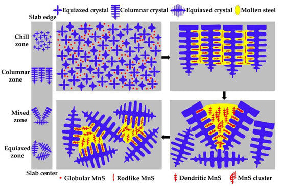
Figure 11.
Schematic drawing of MnS inclusion aggregation mechanism along the slab thickness of the medium carbon 45# steel.
In the chill zone, the high intensity cooling leads to the formation of tiny spherical MnS inclusions between fine equiaxed grains. As the cooling continues, the columnar dendrites grow along the slab thickness, and slim rodlike MnS inclusions are formed between columnar crystals, as well as some small-size dendritic MnS inclusions. Then, a mixed zone arises before the columnar zone completely transformed into equiaxed zone. The large SDAS, high sulfur content and low cooling rate in the mixed zone provide favorable conditions for the formation and growth of MnS inclusions, and finally into large-size closely distributed ones. Furthermore, the equiaxed zone is formed near the slab center, where a large amount of MnS inclusions precipitated between the dendrites.
4.3. Influence of Large-Size MnS Inclusion
As the MnS inclusions are formed at the end of solidification, it can be inferred that they may have some impact on the subsequent solid-state phase transformation. The observed microstructure after etching together with MnS inclusions are presented in Figure 12. Shim et al. [46] reported that coarse MnS particles are inert to the nucleation of intragranular ferrite, and Lin et al. [47,48] suggested that the size of MnS inclusion acting as the nucleation site for ferrite should be smaller than 10 μm. However, Figure 12a–c indicates that ferrites can be formed on dendritic MnS inclusions, even if the average diameter of the inclusion exceeds 52 μm. Figure 12d–f shows that the distribution of MnS inclusions significantly affects the growth of the ferrites and destroys the uniformity of the microstructure, which is likely to cause the anisotropy of mechanical properties of the steel. In other words, this also means that it has great potential to improve the microstructure by controlling the size and distribution of MnS inclusions.
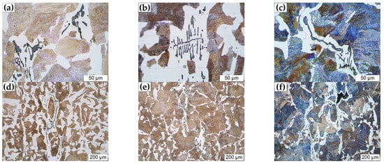
Figure 12.
Effect of MnS inclusions on microstructure of the medium carbon structural steel 45#. (a–c) magnification × 500, (d–f) magnification × 100.
MnS inclusions are also strongly associated with shrinkage and porosity in steel. The dendritic MnS inclusion occurs simultaneously with shrinkage cavity in the mixed zone as shown in Figure 13. The MnS inclusions are formed in solute-rich liquid hindered in the upper part of the dendritic bridge, while the shrinkage in the lower part is hardly compensated by the residual liquid and evolved into cavity, which is mutually confirmed with the sulfur segregation results described above.
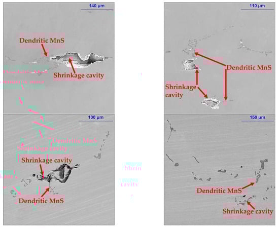
Figure 13.
Relationship between MnS inclusions and shrinkage cavities in the medium carbon structural steel 45#.
5. Conclusions
In the current study, metallographic testing, elemental analysis, SEM-EDS observation, an automatic particle analysis system, and thermodynamic calculation were applied to reveal the solidification macrostructure, sulfur segregation and MnS inclusion evolution along the slab thickness of the medium carbon structural steel 45#. The main findings are as follows:
- (1)
- The optical microscope and SEM-EDS observation of MnS inclusions morphology suggest that the sulfides are in globular, rodlike and dendritic shape, and distribution varies along the slab thickness of the 45# steel, the former is mainly presented near the slab edge, while the latter two are generally found in the columnar zone, mixed zone and equiaxed zone.
- (2)
- Both the automatic particle analysis data and observed 3D morphology indicate that MnS inclusions are aggregated in the mixed zone of the 45# steel slab, where the sulfides have the largest average diameter and the second maximum area fraction along the slab thickness, which are 6.35 μm, 0.025%, respectively.
- (3)
- The thermodynamic calculations together with experimental observations prove that the MnS inclusion in the 45# steel is formed in the residual molten steel between dendrites at the end of solidification. The high intensity cooling leads to the formation of fine globular MnS inclusions near the slab edge, while the large SDAS, high sulfur content and low cooling rate account for the large-size aggregated MnS inclusions in the mixed zone.
- (4)
- The large-size dendritic MnS inclusions can act as the nucleation sites for ferrites, even if the average diameter of the inclusion exceeds 52 μm. Additionally, the distribution of dendritic MnS inclusions significantly destroys the uniformity of the microstructure.
Author Contributions
Conceptualization, X.Y., C.L. and Z.T.; methodology, X.Y., C.L. and Z.T.; formal analysis, Q.Y. and X.Y.; investigation, Q.Y. and X.Y.; writing—original draft preparation, Q.Y. and X.Y.; writing—review and editing, X.Y. and Z.T.; funding acquisition, X.Y., C.L. All authors have read and agreed to the published version of the manuscript.
Funding
The authors are grateful for support from the National Science Foundation China (Grant No. 52004110, No. 52174316, No. 51974139), project funded by China Postdoctoral Science Foundation (Grant No. 2020M671977), Department of education of Jiangxi Province (Grant No. GJJ190482), National Science Foundation Jiangxi (Grant No. 20212ACB204008), Jiangxi University of Science and Technology (Grant No. jxxjbs17003).
Institutional Review Board Statement
Not applicable.
Informed Consent Statement
Not applicable.
Data Availability Statement
Not applicable.
Conflicts of Interest
The authors declare no conflict of interest.
Nomenclature
| SEM | scanning electron microscope |
| EDS | Energy Dispersive Spectrometer |
| SDAS | secondary dendrite arm spacing |
| Type I sulfides | globular sulfides |
| Type II sulfides | rodlike or dendritic sulfides |
| Type III sulfides | angular sulfides |
| CET | columnar-to-equiaxed transition |
| AT | average thickness of different zone |
| SD | standard deviation |
| KMnS | equilibrium constant of reaction for MnS formation |
| aMnS | activity of MnS |
| a[Mn] | activity of Mn |
| a[S] | activity of S |
| fn | activity coefficient of the solute element n |
| w[Mn] | mass fraction of solute element Mn |
| w[S] | mass fraction of solute element S |
| w[n] | mass fraction of solute element n |
| w[m] | mass fraction of solute element m |
| interaction coefficient of element m to n | |
| Tliq | liquidus temperature of the steel |
| Tsol | solidus temperature of the steel |
| Slocal/Saverage | segregation index of sulfur |
| dT/dt | cooling rate during solidification |
| λ2 | secondary secondary dendrite arm spacing value in μm |
| rMnS | size of MnS inclusion |
| K | constant value, 0.85 for the studied 45# steel |
| t | casting time |
| x | coordinates along slab width |
| y | coordinates along slab thickness |
| ρT | density of steel (kg/m3) |
| Cp,T | specific heat |
| kT | thermal conductivity |
| qm | heat flux at the mold wall |
| A and B | constants |
| z | instant length of casting (m) |
| Vc | casting speed |
| N | slab narrow face |
| L | loose side of slab wide face |
| F | fixed side of slab wide face |
| LF | L and F each consumed half of the water flow rate |
References
- Diederichs, R.; Bleck, W. Modelling of Manganese Sulphide Formation during Solidification, Part I: Description of MnS Formation Parameters. Steel Res. Int. 2006, 77, 202–209. [Google Scholar] [CrossRef]
- Ånmark, N.; Karasev, A.; Göran, J.P. The Effect of Different Non-Metallic Inclusions on the Machinability of Steels. Materials 2015, 8, 751–783. [Google Scholar] [CrossRef] [PubMed]
- Wu, M.; Zhao, F.; Yang, Y.; Jiang, B.; Zhang, C.L.; Liu, Y.Z. The Effect of Size and Distribution of MnS Inclusions on the Austenite Grain Growth in a Low Cost Hot Forged Steel. Steel Res. Int. 2018, 89, 1700270. [Google Scholar] [CrossRef]
- Lu, J.; Cheng, G.; Tan, B.; Che, J. Effect of Zr, Al Addition on Characteristics of MnS and Formation of Intragranular Ferrite in Non-Quenched and Tempered Steel. ISIJ Int. 2018, 58, 921–928. [Google Scholar] [CrossRef] [Green Version]
- Diederichs, R.; Bülte, R.; Pariser, G.; Bleck, W. Modelling of manganese sulphide formation during solidification, Part II: Correlation of solidification and MnS formation. Steel Res. Int. 2006, 77, 256–264. [Google Scholar] [CrossRef]
- Liu, H.; Hu, D.; Fu, J. Analysis of MnS Inclusions Formation in Resulphurised Steel via Modeling and Experiments. Materials 2019, 12, 2028. [Google Scholar] [CrossRef] [Green Version]
- Oikawa, K.; Ohtani, H.; Ishida, K.; Nishizawa, T. The Control of the Morphology of MnS Inclusions in Steel during Solidification. ISIJ Int. 1995, 35, 402–408. [Google Scholar] [CrossRef] [Green Version]
- Zheng, L.; Malfliet, A.; Wollants, P.; Blanpain, B.; Guo, M. Effect of Surfactant Te on the Formation of MnS Inclusions in Steel. Metall. Mater. Trans. B 2017, 48, 2447–2458. [Google Scholar] [CrossRef]
- Yoichi, I.; Noriyuki, M.; Kaichi, M. Formation of MnS-type Inclusion in Steel. Tetsu-to-Hagane 1980, 66, 647–656. [Google Scholar]
- Oikawa, K.; Ishi Da, K.; Nishizawa, T. Effect of Titanium Addition on the Formation and Distribution of MnS Inclusions in Steel during Solidification. ISIJ Int. 1997, 37, 332–338. [Google Scholar] [CrossRef]
- Takada, H.; Bessho, I.; Ito, T. Effect of Sulfur Content and Solidification Variables on Morphology and Distribution of Sulfide in Steel Ingots. Trans. Iron Steel Inst. Jpn. 1978, 18, 564–573. [Google Scholar] [CrossRef]
- Wakoh, M.; Sawai, T.; Mizoguchi, S. Effect of S content on the MnS precipitation in steel with oxide nuclei. ISIJ Int. 1996, 36, 1014–1021. [Google Scholar] [CrossRef] [Green Version]
- Shen, P.; Fu, J. Morphology Study on Inclusion Modifications Using Mg–Ca Treatment in Resulfurized Special Steel. Materials 2019, 12, 197. [Google Scholar] [CrossRef] [Green Version]
- Wang, F.; Guo, H.; Liu, W.; Yang, S.; Zhang, S.; Li, J. Control of MnS Inclusions in High- and Low-Sulfur Steel by Tellurium Treatment. Materials 2019, 12, 1034. [Google Scholar] [CrossRef] [Green Version]
- Wu, L.; Zhi, J.; Zhang, J.; Zhao, B.; Liu, Q. Effect of Cerium on the Microstructure and Inclusion Evolution of C-Mn Cryogenic Vessel Steels. Materials 2021, 14, 5262. [Google Scholar] [CrossRef]
- Masana, I. Consideration on Distribution and Size of Dendritic Type II MnS-inclusion in Steel Dendrite Structure. ISIJ Int. 1994, 34, 992–996. [Google Scholar]
- Ito, Y.; Masumitsu, N.; Matsubara, K. Formation of Manganese Sulfide in Steel. Trans. Iron Steel Inst. Jpn. 1981, 21, 477–484. [Google Scholar] [CrossRef]
- Choudhary, S.K.; Ganguly, S.; Sengupta, A.; Sharma, V. Solidification morphology and segregation in continuously cast steel slab. J. Mater. Process. Technol. 2017, 243, 312–321. [Google Scholar] [CrossRef]
- Tao, H.; Hui, Z.; Zhang, M.-L. Research on solidification structure and internal quality defects of 0.1%C-5%Mn Steel. Ironmak. Steelmak. 2020, 47, 351–360. [Google Scholar] [CrossRef]
- Ueshima, Y.; Sawada, Y.; Mizoguchi, S.; Kajioka, H. Precipitation behavior of MnS during / transformation in Fe-Si alloys. Metall. Trans. A 1989, 20, 1375–1383. [Google Scholar] [CrossRef]
- Yoshiyuki, U.; Kohichi, I.; Shozo, M.; Hirobumi, M.; Hiroyuki, K. Analysis of the Rate of Crystallization and Precipitation of MnS in the Resulphurized Free-cutting Steel. Tetsu-to-Hagane 1988, 74, 465–472. [Google Scholar]
- Ye, D.; Wang, Z. Change characteristics of static mechanical property parameters and dislocation structures of 45# medium carbon structural steel during fatigue failure process. Mater. Sci. Eng. A 2001, 297, 54–61. [Google Scholar]
- Ortega, N.; Martynenko, V.; Perez, D.; Martinez Krahmer, D.; López de Lacalle, L.N.; Ukar, E. Abrasive Disc Performance in Dry-Cutting of Medium-Carbon Steel. Metals 2020, 10, 538. [Google Scholar] [CrossRef] [Green Version]
- Ren, Y.; Zhang, L.; Li, S. Transient Evolution of Inclusions during Calcium Modification in Linepipe Steels. ISIJ Int. 2014, 54, 2772–2779. [Google Scholar] [CrossRef] [Green Version]
- Choudhary, S.K.; Ghosh, A. Mathematical Model for Prediction of Composition of Inclusions Formed during Solidification of Liquid Steel. ISIJ Int. 2009, 49, 1819–1827. [Google Scholar] [CrossRef] [Green Version]
- Yang, X.; Zhang, L.; Li, S.; Li, M. Influence of cooling conditions on the hot ductility of Nb-Ti-bearing steels. Metall. Res. Technol. 2015, 112, 604. [Google Scholar] [CrossRef]
- Luo, S.; Wang, B.; Wang, Z.; Jiang, D.; Wang, W.; Zhu, M. Morphology of Solidification Structure and MnS Inclusion in High Carbon Steel Continuously Cast Bloom. ISIJ Int. 2017, 57, 2000–2009. [Google Scholar] [CrossRef] [Green Version]
- Faraji, M.; Wilcox, D.P.; Thackray, R.; Howe, A.A.; Todd, I.; Tsakiropoulos, P. Quantitative Characterization of Inclusions in Continuously Cast High-Carbon Steel. Metall. Mater. Trans. B 2015, 46, 2490–2502. [Google Scholar] [CrossRef]
- Weidner, A.; Krewerth, D.; Witschel, B.; Emmel, M.; Schmidt, A.; Gleinig, J.; Volkova, O.; Aneziris, C.G.; Biermann, H. Microstructure of Non-Metallic Inclusions Identified in Cast Steel 42CrMo4 after Metal Melt Filtration by Novel Foam Filters. Steel Res. Int. 2016, 87, 1038–1053. [Google Scholar] [CrossRef]
- Temmel, C.; Ingesten, N.-G.; Karlsson, B. Fatigue anisotropy in cross-rolled, hardened medium carbon steel resulting from MnS inclusions. Metall. Mater. Trans. A 2006, 37, 2995–3007. [Google Scholar] [CrossRef]
- Brandaleze, E.; Hereñú, S.; Tormo, J.; Alvarez Armas, I. Characterisation of inclusions in resulphurised microalloyed steel. Ironmak. Steelmak. 2013, 40, 216–220. [Google Scholar] [CrossRef]
- Domizzi, G.; Anteri, G.; Ovejero-García, J. Influence of sulphur content and inclusion distribution on the hydrogen induced blister cracking in pressure vessel and pipeline steels. Corros. Sci. 2001, 43, 325–339. [Google Scholar] [CrossRef]
- Gui, L.; Long, M.; Huang, Y.; Chen, D.; Chen, H.; Duan, H.; Yu, S. Effects of Inclusion Precipitation, Partition Coefficient, and Phase Transition on Microsegregation for High-Sulfur Steel Solidification. Metall. Mater. Trans. B 2018, 49, 3280–3292. [Google Scholar] [CrossRef]
- Liu, Z.; Wei, J.; Cai, K. A Coupled Mathematical Model of Microsegregation and Inclusion Precipitation during Solidification of Silicon Steel. ISIJ Int. 2002, 42, 958–963. [Google Scholar] [CrossRef]
- Chen, P.J.; Zhu, C.Y.; Li, G.Q.; Dong, Y.W.; Zhang, Z.C. Effect of Sulphur Concentration on Precipitation Behaviors of MnS-containing Inclusions in GCr15 Bearing Steels after LF Refining. ISIJ Int. 2017, 57, 1019–1028. [Google Scholar] [CrossRef] [Green Version]
- Wang, Y.; Zhang, L.; Zhang, H.; Zhao, X.; Wang, S.; Yang, W. Mechanism and Control of Sulfide Inclusion Accumulation in CET Zone of 37Mn5 Round Billet. Metall. Mater. Trans. B 2017, 48, 1004–1013. [Google Scholar] [CrossRef]
- Jacobi, H.; Schwerdtfeger, K. Dendrite morphology of steady state unidirectionally solidified steel. Metall. Trans. A 1976, 7, 811–820. [Google Scholar] [CrossRef]
- Li, B.; Zhang, Z.; Liu, H.; Luo, M.; Lan, P.; Tang, H.; Zhang, J. Characteristics and evolution of the spot segregations and banded defects in high strength corrosion resistant tube steel. Acta Metall. Sin. 2019, 55, 762–772. [Google Scholar]
- Ji, Y.; Tang, H.; Lan, P.; Shang, C.; Zhang, J. Effect of Dendritic Morphology and Central Segregation of Billet Castings on the Microstructure and Mechanical Property of Hot-Rolled Wire Rods. Steel Res. Int. 2017, 88, 1600426. [Google Scholar] [CrossRef]
- Wu, M.; Ludwig, A. A three-phase model for mixed columnar-equiaxed solidification. Metall. Mater. Trans. A 2006, 37, 1613–1631. [Google Scholar] [CrossRef]
- Pierer, R.; Bernhard, C. On the influence of carbon on secondary dendrite arm spacing in steel. J. Mater. Sci. 2008, 43, 6938–6943. [Google Scholar] [CrossRef]
- Zhang, L.; Yang, X.; Li, S.; Li, M.; Ma, W. Control of Transverse Corner Cracks on Low-Carbon Steel Slabs. JOM 2014, 66, 1711–1720. [Google Scholar] [CrossRef]
- Yang, X.; Zhang, L.; Lai, C.; Li, S.; Li, M.; Deng, Z. A Method to Control the Transverse Corner Cracks on a Continuous Casting Slab by Combining Microstructure Analysis with Numerical Simulation of the Slab Temperature Field. Steel Res. Int. 2018, 89, 1700480. [Google Scholar] [CrossRef]
- Yang, X.; Zhang, L.; Zhang, R.; Yang, W. Analysis of flaws detected by ultrasonic in heavy and medium steel plate. Steelmaking 2013, 29, 48–52. [Google Scholar]
- Wang, K.; Yu, T.; Song, Y.; Li, H.-X.; Liu, M.-D.; Luo, R.; Zhang, J.-Y.; Fang, F.-S.; Lin, X.-D. Effects of MnS Inclusions on the Banded Microstructure in Non-quenched and Tempered Steel. Metall. Mater. Trans. B 2019, 50, 1213–1224. [Google Scholar] [CrossRef]
- Shim, J.H.; Oh, Y.J.; Suh, J.Y.; Cho, Y.W.; Shim, J.D.; Byun, J.S.; Lee, D.N. Ferrite nucleation potency of non-metallic inclusions in medium carbon steels. Acta Mater. 2001, 49, 2115–2122. [Google Scholar] [CrossRef]
- Lin, C.K.; Pan, Y.C.; Su, Y.; Lin, G.R.; Weng-Sing, H.; Jui-Chao, K. Effects of Mg-Al-O-Mn-S inclusion on the nucleation of acicular ferrite in magnesium-containing low-carbon steel. Mater. Charact. 2018, 141, 318–327. [Google Scholar] [CrossRef]
- Xing, L.; Fan, X.; Wang, M.; Zhao, L.; Bao, Y. The Formation Mechanism of Proeutectoid Ferrite on Medium-Carbon Sulfur-Containing Bloom. Metall. Mater. Trans. B 2021, 52, 3208–3219. [Google Scholar] [CrossRef]
Publisher’s Note: MDPI stays neutral with regard to jurisdictional claims in published maps and institutional affiliations. |
© 2021 by the authors. Licensee MDPI, Basel, Switzerland. This article is an open access article distributed under the terms and conditions of the Creative Commons Attribution (CC BY) license (https://creativecommons.org/licenses/by/4.0/).