Abstract
This study examined the effects of the strain rate and thermal softening on large-scale ductile fracture in ship collisions using a rate-dependent combined localized necking and fracture model. A Johnson–Cook type-hardening model, consisting of strain hardening, rate-sensitivity, and thermal softening terms, was adopted together with an associated flow rule. The temperature was treated as an internal state variable and was calculated from the plastic strain energy using a strain-rate-dependent weighting function under fully isothermal and adiabatic conditions. At every time increment, the fracture locus was updated based on the temporal strain rate, whereas the necking locus was coupled with the hardening law, which was dependent on both the strain rate and temperature. The damage indicator framework was used to consider the non-proportional loading paths. The dynamic shell-element failure model was verified through plate-panel penetration tests and applied to a large-scale ship collision analysis involving a struck ship/ship-shaped offshore installation and a supply vessel. The effects of the loading rate and impact energy were assessed in terms of the global behavior of the structure and observed failure modes.
1. Introduction
Assessments of the resistance of ship and offshore structural components subjected to extreme and accidental loadings, such as collision and grounding [1], explosion and blast accompanied with fire [2,3], and slamming [4], are impact engineering problems. Under impact loads, the structural response may differ considerably from that under a quasi-static load [5] because the mechanical properties are affected significantly by the loading speed and resulting strain rates. In the context of ship collision analysis, although certain computational modeling approaches use the dynamic material properties, e.g., those recommended by Paik [6], incorporating strain-rate effects and capturing the actual material behavior is a challenge for structural analysts. This can be attributed to modeling uncertainties and the lack of a proper definition of the strain-rate effects in the context of nonlinear finite element analysis (NLFEA) [7,8,9].
Ship collisions are typical low-velocity impact events, where the impact velocity is less than 25 m/s. Gruben et al. [10] reported that the low-velocity impact response of scaled models of stiffened panels is comparable to the quasi-static response. On the other hand, the positive strain-rate sensitivity of the material flow stress increases the deformation resistance to a certain extent. Many other experimental and numerical studies on small-scale structural components subjected to mass impact loads have been conducted. Examples include reference [11], which highlighted the necessity of including the positive strain-rate sensitivity of the flow stress for an accurate prediction of plastic deformation. The Cowper–Symonds model [12] may be the most widely used constitutive model for the strain-rate effect, in which the constants are calibrated based on the lower yield stress of the material. This model scales up the flow stress curve for a given strain rate with the same amount for all equivalent plastic strains as for the initial flow stress corresponding to a lower yield stress. In simple methods based on rigid-plastic mechanisms, this simple model is often used to tune the prediction with experimental test results [13].
On the other hand, NLFEA predictions are more sensitive to the definitions of rate-dependent flow stress [8], and care must be taken when using Cowper-Symonds type models. The enhanced flow stress at high strain rates depends on the amount of plastic strain [14]. A certain fraction of the plastic work expended during plastic deformation is dissipated as heat, which leads to thermal softening, eventually overriding strain-rate hardening. Another constitutive model used widely, called the empirical Johnson–Cook model [15], considers the strain-rate and thermal softening effects separately but assuming fully adiabatic conditions for all strain rates. Both the rate-dependency of the flow stress and the prediction of fracture initiation under a dynamic load require special consideration. The simple approaches proposed by Paik [6] and Jones [5] consider the percentage elongation of tension test specimens at high strain rates, termed “dynamic fracture strain”, as the critical failure strain for NLFEA [16]. As discussed in detail by Cerik et al. [17,18], however, predicting the initiation of ductile fracture using finite shell elements requires more advanced models that address the following: Different fracture mechanisms (fracture with and without through-thickness necking), the variability of the stress state throughout the load to fracture initiation, and distinguishing membrane and bending deformation. An essential point for the ship collision problem is that most structural members fracture under biaxial membrane stretching, which is preceded by localized necking. Localized necking-based shell element failure models, in which parameter identification requires only the flow stress of the material, are well justified for the quasi-static loading case [17,18,19,20,21,22]. Under a dynamic load, the same models can be used with properly defined rate-dependent flow stress curves.
The primary aim of this study was to provide a definition of the strain-rate effect problem for the NLFEA of impact engineering applications using shell elements and assess the combined effect of strain-rate hardening and dynamic fracture on the ship collision response analysis. The refined computational model developed by Cerik and Choung [21], which extended the plasticity and ductile fracture model for the shell elements advocated and validated in [17,22] for dynamic loads, was introduced as a viable means for treating strain rate effects. This model was applied to a large-scale collision case study to quantify the effects of the loading speed on the structural response and deformation behavior. It is the first time that the combined effect of strain-rate hardening and dynamic fracture is studied for the ship collision problem. In particular, the sensitivity of the numerical simulation of low-velocity impact on the hardening behavior, which is affected by deformation induced thermal softening under adiabatic condition, was considered. A comparison with predictions from the Cowper–Symonds equation, which omits this effect, was also presented, and the implications of standard practices observed in the literature were discussed.
2. Material Model
First, a detailed description of the adopted material model is given. With the aid of the adopted constitutive model, the dynamic effects can be assessed in more detail compared to many other studies reported in the literature that rely on simple models.
2.1. Plasticity Model
The plasticity model proposed by Roth and Mohr [23] was used. The yield function is described as follows:
where , k, and are the Cauchy stress tensor, deformation resistance, and von Mises equivalent stress, respectively. An associated flow rule was chosen to describe the evolution of the plastic strain tensor. Following the Johnson–Cook model [15], the deformation resistance was decomposed into strain hardening, strain rate hardening, and thermal softening terms in a multiplicative format as follows:
where is the equivalent plastic strain (work-conjugate of von Mises equivalent stress); is the equivalent plastic strain rate, and T is the temperature.
The strain hardening behavior was modeled using a linear combination of a power law (Swift law) [24] and a saturation law (Voce law) [25], as follows:
where is the weighting factor between the two hardening laws. The power and saturated hardening laws are expressed as in the following equations:
The strain-rate hardening term used in the Johnson–Cook model [15] is as follows:
where C is the strain-rate sensitivity parameter and is the reference strain rate. The thermal softening term in the Johnson–Cook model [15] was used as follows:
with the exponent m, the reference temperature Tr, and the melting temperature Tm of the material.
If temperature is treated as an external state variable, then a full thermo-mechanical analysis is necessary. However, detailed computation of temperature fields in crash and forming simulations is often omitted because of computational cost and the duration of the loading, which often yields an adiabatic condition. Therefore, the temperature is considered as an internal state variable and its evolution with increasing equivalent plastic strain was calculated using the following equation:
where is the Taylor–Quinney coefficient, ρ is the material density, and Cp is the specific heat of the material. Roth and Mohr [23] introduced a regulating term, ω, to account for the transition from isothermal to adiabatic conditions. The expression for ω is as follows:
where and define the limits of the isothermal and adiabatic domains, respectively. The recommended practice is that is assumed to be equal to [23]. It should be noted that according to Equation (8), temperature increases only with plastic deformation. Therefore, thermal softening effect on elastic moduli was not considered in the present study.
2.2. Rate-Dependent Shell Element Fracture Initiation Model
A rate-dependent extension of the DSSE-HC model [21,26] was used. Ductile fracture without prior localized necking was predicted using the strain rate modified version of the Hosford–Coulomb (HC) model [23]. The onset of fracture was estimated using a fracture indicator, D, at an equivalent plastic strain of , if the following condition is met:
Here, the denominator is the HC fracture locus, which is expressed as a function of the two stress state parameters: Stress triaxiality, and the Lode angle parameter, :
where is the first invariant of the Cauchy stress tensor and is the third invariant of the stress deviator tensor, s. Note that under plane stress conditions, there is a one-to-one relationship between the stress triaxiality and Lode angle parameter:
The HC fracture initiation model reads as follows:
with
The model parameters are {a, b, c}. In references [27,28], representative values of these parameters for marine structural steels are provided. The transformation coefficient, nf, should be taken as 0.1 [26]. Parameter b controls the overall magnitude of strain fracture. Roth and Mohr [27] proposed a strain-rate modification of the HC model using a Johnson–Cook type logarithmic multiplier through this parameter as follows:
where b0 is the strain to fracture for uniaxial and equi-biaxial tension at the reference strain rate (under quasi-static loading regime), and γ controls the strain-rate sensitivity.
The Domain-of-Shell-to-Solid-Equivalence (DSSE) concept, which is a forming limit curve accounting for bending-induced delay of localized necking, was used to predict fracture preceded by localized necking [29]. The onset of localized necking was estimated using a fracture indicator, N, at an equivalent plastic strain of , when the following condition is met:
with the DSSE localized necking locus given as follows:
The parameter d is the sole parameter of the DSSE model. The exponent pf was taken as 0.01. A rate-dependent version of the DSSE was proposed in reference [21] by considering the instantaneous hardening rate of the material, which is affected by the instantaneous strain rate and temperature rise due to plastic deformation. The parameter d was evaluated at each time increment using the Considère criterion for the plane-strain tension condition , which can be expressed as
The above equation is solved for the equivalent plastic strain corresponding to the localized necking, . The partial derivatives in the above equation were given as follows:
and are substituted into Equation (20) to yield the equation
This implicit equation was solved for d using the appropriate root-finding methods.
The material model was implemented in a user-defined material subroutine VUMAT for use in Abaqus/Explicit with shell elements. Failure without necking was checked at each through-thickness integration point of a shell element, regardless of the status of the other integration points. The failure due to necking was assessed considering the failure of all integration points through the thickness. Here, failure means that the stress tensor components of the through-thickness integration point were set to zero. Moreover, a shell element was deleted (eroded) if all through-thickness integration points fail. For the former case, i.e., failure without necking, a progressive failure of through-thickness integration points before the element deletion is possible. More details of the numerical implementation of the material model and verification with low-velocity impact tests on steel sheets [30] were provided in reference [21].
3. Simulation of Panel Penetration Tests
First, the model was applied to the simulation of panel penetration tests reported by Liu et al. [31,32]. The panel penetration tests are laboratory scale representatives of the most common failure mode observed in a ship side-shell collision. It is therefore a common practice to validate and calibrate material models using these types of tests before applying them in a full-scale ship collisions analysis. A comparison of quasi-static and dynamic tests is necessary to quantify the importance of dynamic effects. The tests were aimed to mimic side shell collision involving a bulbous bow. In reference [31], both quasi-static and low-velocity impact tests on square steel plates were reported. The square plates were fixed at all four edges and had an effective span of 1000 mm. The plate thickness was 4 mm. The quasi-static test was conducted by forcing a hemispherical indenter to penetrate through the plate at its center with a velocity of 10 mm/min. The tip radius of the indenter was 75 mm. The low-velocity impact test was conducted using a drop-weight impact testing facility. The total mass of the impactor was 1350 kg, and the drop height was 2 m, which yielded an impact velocity of 6.2 m/s. The same research group reported low-velocity impact tests on stiffened square plates [32]. Three flat bar stiffeners were welded on 1060 × 1060 mm square plates with a 250 mm spacing. The thickness of the plate and stiffeners was 6 mm. The mass of the impactor was 1350 kg, but the drop height was increased to 3.7 m to achieve sufficient impact energy to rupture the target panel. In both experimental studies, the material of the test models was mild steel with a yield stress of 245 MPa and an ultimate tensile strength of 361 MPa.
The simulations of these tests were performed using FEA software Abaqus/Explicit and the VUMAT subroutine using the described material model for the low-velocity impact tests and the original DSSE-HC model (excluding rate effects) for the quasi-static test. Finite element models of the target unstiffened and stiffened panels were developed using four-node shell elements with five integration points through the thickness. The indenter was modeled as a rigid surface. The mesh size in the order of plate thickness was necessary to capture stress gradients close to the impacted area.
In the quasi-static test simulation, a displacement boundary condition in the impact direction was specified at the reference node of the rigid punch with all the remaining degrees of freedom constrained. For the low-velocity impact simulations, an initial velocity condition was specified at the reference node of the rigid indenter in the impact direction. A general contact interaction was defined between the target panels and the indenter. In addition, self-contact was defined between the surfaces of the test model. A friction coefficient of 0.3 reported in references [31,32] was used for the contact between the surfaces. Both the quasi-static and low-velocity impact test simulations consisted of one explicit dynamic step. The total simulation times were 0.4 s and 0.04 s, respectively. The former was long enough to yield quasi-static conditions, i.e., the impacted structure had negligible kinetic energy compared to its strain energy.
The power-law hardening parameters were obtained from reference [31]. Initial attempts with the given hardening law parameters yielded satisfactory results in the quasi-static test simulation. Therefore, only the Swift law was used as the strain hardening model. The other plasticity model parameters and fracture model parameters, particularly those related to the dynamic effects, were obtained from the literature [21]. The hardening ratio of the test model material was comparable to that of typical high-tensile strength steels. Therefore, the values from the literature were appropriate. Table 1 lists the material parameters.

Table 1.
Material model parameters used in panel penetration simulations.
Figure 1 presents the force-displacement curves for the unstiffened plate simulations. The test results and the numerical simulations showed close agreement for the case of the quasi-static test. In the test results, the sudden decrease in force, which corresponds to the rupture of the plate, was not given in the data provided in reference [31]. On the other hand, the test was stopped at the visible rupture initiation. The numerical simulation predicted the rupture initiation slightly later than the test result. There were larger discrepancies between the test and numerical simulation results in the drop-weight penetration test. Regarding the uncertainties involved in the dynamic tests [6], the overall trends in the force–displacement response and the instance of fracture initiation were captured with relatively good accuracy.
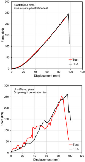
Figure 1.
Force–displacement curves for the unstiffened plate simulations.
In both quasi-static and dynamic simulations, failure was associated with localized necking. Figure 2 presents the localized necking indicator plot before and after fracture initiation, followed by the formation of petals. The predicted failure pattern was in good agreement with the post-mortem test model photo reported elsewhere [31]. Fracture initiated around the necking circle at multiple locations. This was followed by the formation of cracks propagating in the direction perpendicular to the necking circle and petalling. Crack propagation was simulated by successively deleting the failed elements. Note that the process associated with petalling, which involves tearing of the plate due to in-plane stretching, was also driven by localized necking. Of particular interest in the dynamic simulations was the temperature increase and strain rate magnitudes that may affect fracture initiation. Figure 3 presents plots of these two state variables before the predicted instant of fracture initiation. The temperature increase was of negligible order, while the strain rates reached locally high values.
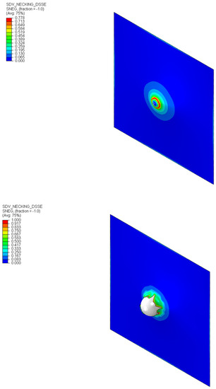
Figure 2.
Localized necking indicator plots before and after fracture initiation.
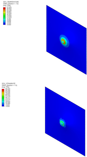
Figure 3.
Temperature increase and strain rate plots before fracture initiation.
The results obtained for the stiffened panel were also comparable to the test results. Figure 4 shows the predicted force–displacement curve and compares it with the test result. Although the predicted force levels were slightly higher than the test, the fracture initiation was predicted quite accurately. The predicted values did not differ much from the unstiffened plates, where failure was again driven by localized necking and initiated in the necking circle. Further penetration of the indenter caused a fracture in the stiffener. The predicted failure modes were the same as in the test reported elsewhere [32]. Therefore, the simulations of panel penetration tests were deemed successful, and the material model was validated.
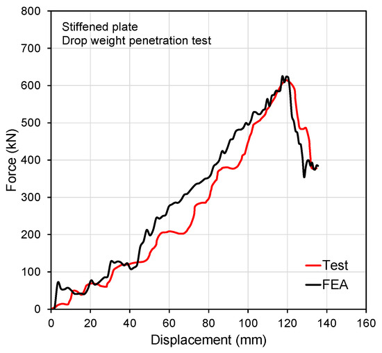
Figure 4.
Force–displacement curves for the stiffened panel simulations.
4. Ship Collision Analysis
4.1. Collision Sceanario
The structural performance of ship structures against collisions is generally assessed by decoupling the external dynamics and internal collision mechanics. This study considered the internal collision mechanics of the side structures of a struck ship/ship-shaped offshore installation (FPSO—floating production storage and offloading-unit), emphasizing the influence of the material rate-dependent behavior. The adopted collision scenario involves a typical case, where a striking supply vessel bow penetrates with the double hull side structure of an idealized FPSO, as shown in Figure 5. The collision angle was assumed to be 90° (right-angled collision). The striking collision occurred at the mid-length of the struck ship. The first contact point of the striking ship was with the bulbous bow between two side longitudinal stiffeners and two transverse frames in the struck ship. The stem of the striking ship hit the deck corner between the two transverse frames. The spacing of the double hull was 2.9 m, the transverse frame spacing was 3.64 m, and the stiffener spacing was 0.8 m. The side-shell plate thickness at the impact point was 16 mm. The FPSO was assumed to be at a standstill and fully laden, whereas the supply vessel was close to full draught. The total mass of the supply vessel, including the added mass, was assumed to be 10,000 tons. The initial velocity of the supply vessel was 6, 8, 10, and 14 knots, which yielded a kinetic energy of 47.63, 84.67, 132.3, and 259.32 MJ, respectively.
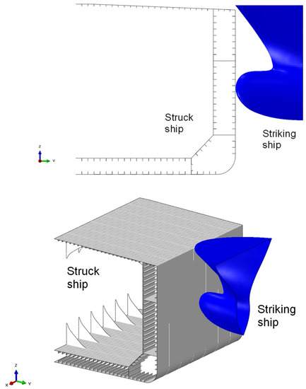
Figure 5.
Considered collision scenario and modeling extents.
4.2. Finite Element Modeling
Based on the described collision scenarios, the simulations were performed using the Abaqus/Explicit computer program. One mid-ship cargo hold of the struck ship between the adjacent transverse bulkheads was taken as the extent of structural crashworthiness analysis. The effects of the global hull girder horizontal bending were limited by taking the relative size of the supply vessel and FPSO into account [33]. Like the FE model used by Paik et al. [34] and Haris and Amdahl [35], all degrees of freedom were constrained at the transverse bulkheads and along the ship centerline. These assumptions were based on the observations reported by Liu et al. [36] on the coupled and decoupled analysis techniques for right-angled ship collisions. They concluded that the decoupled method is appropriate for appraising ship-side structures subjected to a collision load and plastic deformation. Moreover, failure is not affected by the motions of the struck ship and boundary conditions in right-angled collisions.
In ship collision analysis, the mesh density should be selected considering the computational cost and accurately capturing the folding, tearing, and rupture of the structural components in the vicinity of the contact position between the hit bodies. In the adopted shell-element fracture model, which combines a localized necking model and ductile fracture model, the element size should be in the order of several multiples of the plate thickness/neck size.
In the present case study, a finer mesh employing 100 mm × 100 mm elements was applied on the parts, where large plastic deformation occurs (certain parts of the outer and inner shell and deck corner). This element size corresponds to approximately six times the side shell thickness. On the other hand, an element size of approximately 400 mm was applied to other parts. As shown in Figure 6, transition elements were applied between the fine and coarsely meshed areas. Four node linear shell elements with reduced integration were applied. The bow model was comprised of meshed rigid elements, as shown in Figure 6. This assumption was made to focus solely on the structural crashworthiness of the struck ship. In an actual collision scenario, however, the bow structure could deform and absorb the impact energy to some extent based on its relative stiffness. The total number of elements was 50,563.
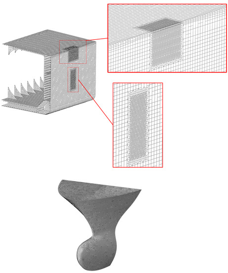
Figure 6.
Finite element models and mesh of the struck FPSO and striking supply vessel bow.
The struck ship was made of high-tensile strength steel. The assumed material parameters under quasi-static conditions were obtained from reference [37]. The additional parameters related to the rate-dependency were assumed to be similar to those reported by Roth and Mohr [21] for DP590 grade high-tensile strength steel. Table 2 lists the adopted material parameters. When choosing the material parameters, attention was given on obtaining decreasing strain hardening due to thermal softening. Figure 7 presents plots of the flow stress at different strain rates. In the adiabatic domain, the thermal softening effect becomes dominant at considerable strain, which is typically observed for steels used in ship construction [37,38]. Figure 8 presents the ductile fracture and localized necking loci under proportional loading paths for the same strain rates, where the former and latter are plotted using the continuous lines and dashed lines, respectively.
Table 2.
Material model parameters used in ship collision analysis.
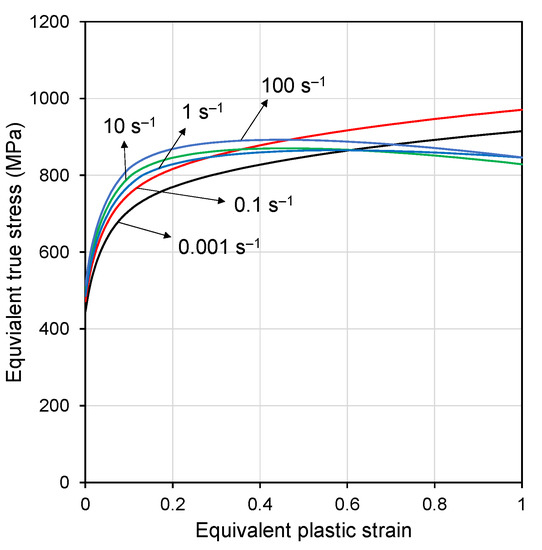
Figure 7.
Flow stress curves at different strain rates.
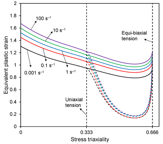
Figure 8.
Ductile fracture and localized necking loci under proportional loading paths at different strain rates.
The contact between the colliding bodies and the self-contact of surfaces was modeled using the general contact algorithm in Abaqus. The friction coefficient was assumed to be 0.3, which is generally applied in ship collision analysis [35]. No shear stress limit was set to allow for sliding because it has a minor influence on the outcome of the simulations.
The simulations were run using two different methods to assess the influence of incorporating strain-rate effects. In the first method, the initial velocity was set to the striking ship. The analysis was run until the struck structure dissipated the total impact energy. Rate-dependent material behavior was fully considered in the first approach. In the second method, displacement-controlled analysis was conducted by allowing the striking ship to penetrate the inner shell of the struck ship in a quasi-static manner. The analysis was run for a sufficiently long time such that the inertial effects were negligible. In this second approach, rate-dependent behavior was not included.
5. Computational Results and Discussion
Figure 9 shows the collision force as a function of the penetration curves of the struck side ship with or without considering the rate-dependent material and dynamic effects. The collision force and displacement corresponded to the impact force component and displacement in the direction of the striking ship penetration. Depending on the kinetic energy, the instant at which the striking ship comes to a standstill differs, and only the case of a 14-knot collision speed caused the rupture of the inner shell. The predicted instant of the rupture of the outer shell was relatively unaffected when the rate-dependent material behavior was considered. Rupture of the outer shell was followed by a sudden decrease in force. Some differences between the structural responses of different impact velocities and quasi-static analysis were evident after the outer shell was ruptured when the striking ship penetrated further. This can be attributed to buckled and folded structural members, which experience relatively high strain rates. On the other hand, these differences are marginal, and the collision velocities considered yielded similar results. Moreover, the agreement between the quasi-static and dynamic analysis results for the inner shell rupture prediction was noticeable. In general, the global response in terms of collision force-penetration and the absorbed energy–penetration curves were governed mainly by the failure of the outer and inner side panels. In all simulations, the failure mode of the deck was folding and crushing of the deck-stiffened panel without any tensile tearing but localized surface cracking on the folded plating. The occurrence of this type of fracture had a minor influence on the global response. In addition, as the striking ship velocity range considered covered the generally encountered ship collision velocities, it was concluded that the structural crashworthiness assessment using a displacement-controlled analysis under quasi-static assumption was deemed appropriate.
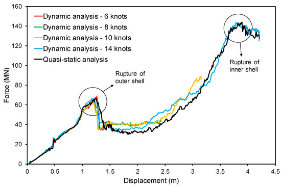
Figure 9.
Force–displacement curves obtained for different speeds and analysis models.
The energy absorption capacity of the struck structure and the extent of structural damage are essential in ship collision analysis. Figure 10 presents the deformation stages of the outer shell predicted by dynamic (14 knots) and quasi-static analyses. The snapshots in Figure 10 show bulb penetration and illustrate the rupture process of the outer shell. The sub-figures on the top-left correspond to the first peak observed in the force–displacement curve. The other sub-figures correspond to the instants associated with the decrease in force after the first peak. The contours show the necking indicator. The rupture mechanism of the outer (and inner) side panel, subjected to biaxial pre-dominantly membrane stretching, is localized necking preceding fracture. The location of fracture initiation and propagation of the crack predicted with the rate-dependent and -independent DSSE models were similar. In addition, the adopted mesh size was fine enough for modeling the collision footprint of the striking bulbous bow accurately. The damage extent was significant for residual strength assessments of the ship hull girder using simplified approaches.
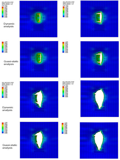
Figure 10.
Different stages of rupturing of the outer shell predicted in dynamic and quasi-static analyses.
Figure 11 shows the instantaneous equivalent plastic strain rate and temperature increase in the outer shell panel, including longitudinal stiffeners, as obtained from dynamic analysis. Before fracture initiation in the outer shell plating, the strain rates were very low. Temporal high strain rates up to 30 s−1 were observed in the stiffeners after the progression of structural damage. On the other hand, the temperature increased gradually in a broader area of the outer shell plating but did not reach high values or cause significant thermal softening before a fracture initiation. Locally, large temperature increases were observed in the secondary members. Note that this temperature increase, which is due to the transformation of plastic work into heat, occurs only during a very short period of impact and is affected by the ambient temperature (adiabatic process). Similar observations were made on deck crushing and folding. Highly strained elements failed by ductile fracture without necking, which was predicted using the HC model.
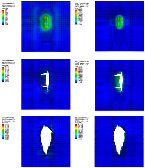
Figure 11.
Equivalent plastic strain rate and temperature increase in the outer shell panel at various stages of rupturing.
Fracture preceded by necking is the dominant failure mechanism in a typical ship-side collision. The adopted rate-dependent combined necking and fracture model provided insights into the local strain rate variations and temperature increase in deforming and failing structural members. On the other hand, necking-based fracture modeling ignored the post-necking response and did not attempt to model the localization associated with high strain rates and temperature increases. In a low-velocity impact, the strain rate and thermal softening only have marginal influence on the fracture initiation preceded by localized necking.
Further analyses were conducted following the common practices used in the ship collision analysis. The Cowper-Symonds model is used mainly for the inclusion of dynamic effects on flow stress. Following the Cowper–Symonds model, the deformation resistance function can be written as follows:
where the Cowper–Symonds dynamic hardening power law is given by the following:
The commonly cited Cowper–Symonds coefficients in the literature for high-tensile strength steels were C = 3400 s−1 and q = 5 [6]. Note that these coefficients were calibrated based on the initial flow stress. Storheim and Amdahl [7] attempted to calibrate these coefficients for DH36 grade steel, considering the average flow stress. They suggested that the coefficient C can be as large as 400,000 s−1. An increasing C means a decreasing strain-rate hardening effect. Only marginal differences between the dynamic and quasi-static simulations of ship collision were observed [7] when the calibrated coefficient based on average flow stress was used.
The current practices do not consider the combined effects of strain-rate hardening and dynamic fracture. A constant fracture strain of 0.23 was adopted in the present study, which is close to the average localized necking limit (equivalent plastic strain) in the domain bounded by plane strain tension and equi-biaxial tension. Note that strain-rate effects are relatively low in this region.
Figure 12 shows the simulation results for the same cases, as described earlier. A significantly larger first peak force and energy dissipation were predicted compared to the quasi-static simulation ignoring any dynamic effect. The deviations became large as the collision speed increased. Considering early remarks by Storheim and Amdahl [7], this is certainly an overestimation of the dynamic hardening factor (increase rate of flow stress), as the dynamic hardening factor varies significantly from initial yield to large plastic strains (see Figure 7). The results obtained using the Cowper–Symonds model and a stress state- and rate-independent fracture model highlights that the inclusion of dynamic effects following the common practice overestimate the energy absorption of the struck ship. On the other hand, with this constitutive modeling approach, the effects of strain rate on fracture cannot be assessed directly.
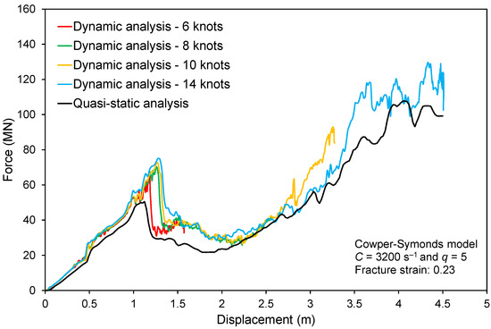
Figure 12.
Force–displacement curves obtained for different speeds using the Cowper–Symonds model and comparison with quasi-static analysis results.
6. Conclusions
In the present study, an advanced rate-dependent plasticity and shell fracture model was used to assess the importance of strain-rate effects in large-scale ship collision analysis. Based on numerical computations, the following conclusions were drawn:
- Inclusion of strain rate hardening and thermal softening yields comparable results to the quasi-static simulation of ship collision problem. Therefore, these effects should be omitted from a practical assessment of ship structural crashworthiness analysis against collisions.
- Dynamic material behavior was considerably different from the quasi-static case; however, the plasticity and fracture strain-rate sensitivity lost their importance in low-velocity impact simulations of large-scale problems.
- The impact velocity has a minor effect on the structural response, which is observed only after a complete rupture of the outer shell plating and during the failure process of secondary members by buckling, folding, and tearing.
- Fracture preceded by localized necking is the dominant failure mode observed in ship-side collision. In the case of low-velocity impact, strain rate and thermal softening have a negligible influence on the fracture initiation of this type of failure.
- The commonly used Cowper–Symonds model for inclusion of strain rate effects and using a constant fracture strain yields a significant overestimation of absorbed energy by the struck ship, and the differences between quasi-static and dynamic simulations were significant. It is concluded that the common practice yields non-conservative results.
Future work in this area may involve exploiting the temperature effect term for extreme ambient temperatures, such as the low-temperature conditions in the Arctic Sea [39], cryogenic conditions in an LNG tank [40,41], and elevated temperatures associated with fire [42,43].
Author Contributions
Conceptualization, B.C.C. and J.C.; methodology, B.C.C.; software, B.C.C.; validation, B.C.C.; formal analysis, B.C.C.; investigation, B.C.C.; resources, J.C.; data curation, B.C.C.; writing—original draft preparation, B.C.C. and J.C.; writing—review and editing, J.C.; visualization, B.C.C.; supervision, J.C.; project administration, J.C.; funding acquisition, J.C. All authors have read and agreed to the published version of the manuscript.
Funding
This work was supported by the Brain Pool Program through the National Research Foundation of Korea (NRF), funded by the Ministry of Science and ICT (2017H1D3A1A01055137), and by an INHA Research Grant.
Institutional Review Board Statement
Not applicable.
Informed Consent Statement
Not applicable.
Data Availability Statement
The data presented in this study are available on request from the corresponding author. The data are not publicly available due to funding requirements.
Conflicts of Interest
The authors declare no conflict of interest.
Nomenclature
| Weighting factor in combined Swift-Voce hardening law | |
| Voce hardening law parameter | |
| Fracture strain rate sensitivity parameter | |
| Reference strain rate for adiabatic condition | |
| Localized necking strain under proportional loading | |
| Fracture strain under proportional loading | |
| Reference strain rate for isothermal condition | |
| Pre-strain in Swift hardening law | |
| Reference strain rate | |
| Equivalent plastic strain | |
| Equivalent plastic strain rate | |
| Stress triaxiality | |
| Taylor-Quinney coefficient | |
| Lode angle parameter | |
| Material density | |
| Cauchy stress tensor | |
| von Mises equivalent stress | |
| Regulating term for transition from isothermal to adiabatic condition | |
| A | Swift law parameter |
| C | Strain-rate hardening sensitivity parameter |
| Cp | Material specific heat |
| D | Ductile fracture indicator |
| E | Young’s modulus |
| I1 | First invariant of stress tensor |
| J2, J3 | Second and third invariants of deviatoric stress tensor |
| N | Localized necking indicator |
| Q | Voce law parameter |
| T | Temperature |
| Tm | Material melting temperature |
| Tr | Reference temperature |
| a, b, c | Hosford-Coulomb model parameters |
| f2, f2, f3 | Lode angle-dependent functions in Hosford-Coulomb model |
| g1, g2 | Stress triaxiality-dependent functions in DSSE model |
| k | Deformation resistance function |
| Strain hardening function | |
| Strain-rate hardening function | |
| Voce hardening law parameter | |
| Swift hardening law | |
| Thermal softening function | |
| Voce hardening law | |
| m | Thermal softening exponent |
| n | Swift law exponent |
| nf | Hosford-Coulomb model transformation coefficient |
| pf | DSSE model exponent |
| q | Cowper-Symonds model exponent |
References
- Liu, B.; Pedersen, P.T.; Zhu, L.; Zhang, S. Review of experiments and calculation procedures for ship collision and grounding damage. Mar. Struct. 2018, 59, 105–121. [Google Scholar] [CrossRef] [Green Version]
- Kim, J.H.; Baeg, D.Y.; Seo, J.K. Numerical investigation of residual strength of steel stiffened panel exposed to hydrocarbon fire. J. Ocean. Eng. Technol. 2021, 35, 203–215. [Google Scholar] [CrossRef]
- Ki, M.S.; Park, B.J. An experimental study on the h-beam under fire load in open space. J. Ocean. Eng. Technol. 2021, 35, 59–74. [Google Scholar] [CrossRef]
- Jeong, H.J.; Koo, W.; Kim, S.J. Numerical study on wave run-up of a circular cylinder with various diffraction parameters and body drafts. J. Ocean. Eng. Technol. 2020, 34, 245–252. [Google Scholar] [CrossRef]
- Jones, N. Some recent developments in the dynamic inelastic behaviour of structures. Ships Offshore Struct. 2006, 1, 37–44. [Google Scholar] [CrossRef]
- Paik, J.K. Practical techniques for finite element modeling to simulate structural crashworthiness in ship collisions and grounding (Part I: Theory). Ships Offshore Struct. 2007, 2, 69–80. [Google Scholar] [CrossRef]
- Samuelides, M. Recent advances and future trends in structural crashworthiness of ship structures subjected to impact loads. Ships Offshore Struct. 2017, 10, 488–497. [Google Scholar] [CrossRef]
- Storheim, M.; Amdahl, J. On the sensitivity to work hardening and strain-rate effects in nonlinear FEM analysis of ship collisions. Ships Offshore Struct. 2017, 12, 100–115. [Google Scholar] [CrossRef]
- Storheim, M.; Alsos, H.S.; Amdahl, J. Evaluation of nonlinear material behaviour for offshore structures subjected to accidental actions. J. Offshore Mech. Arctic Eng. 2018, 140, 041401. [Google Scholar] [CrossRef] [Green Version]
- Gruben, G.; Sølvernes, S.; Berstad, T.; Morin, D.; Hopperstad, O.S.; Langseth, M. Low-velocity impact behaviour and failure of stiffened steel plates. Mar. Struct. 2017, 54, 73–91. [Google Scholar] [CrossRef]
- Cerik, B.C.; Shin, H.K.; Cho, S.R. On the resistance of steel ring-stiffened cylinders subjected to low-velocity mass impact. Int. J. Impact Eng. 2015, 84, 108–123. [Google Scholar] [CrossRef]
- Cowper, G.; Symonds, P. Strain hardening and strain rate effects in the loading of cantilever beams. In Technical Report, No. 28; Division of Applied Mathematics, Brown University: Providence, RI, USA, 1957. [Google Scholar]
- Jones, N. Dynamic inelastic response of strain rate sensitive ductile plates due to large impact, dynamic pressure and explosive loadings. Int. J. Impact Eng. 2014, 74, 3–15. [Google Scholar] [CrossRef]
- Choung, J.; Nam, W.; Lee, J.Y. Dynamic hardening behaviors of various marine structural steels considering dependencies on strain rate and temperature. Mar. Struct. 2013, 32, 49–67. [Google Scholar] [CrossRef]
- Johnson, G.R.; Cook, W.H. A constitutive model and data for metals subjected to large strains, high strain rates and high temperatures. In Proceedings of the 7th International Symposium on Ballistics, The Hague, The Netherlands, 19–21 April 1983; pp. 541–547. [Google Scholar]
- Ko, Y.G.; Kim, S.J.; Sohn, J.M.; Paik, J.K. A practical method to determine the dynamic fracture strain for the nonlinear finite element analysis of structural crashworthiness in ship-ship collisions. Ships Offshore Struct. 2018, 13, 412–422. [Google Scholar] [CrossRef] [Green Version]
- Cerik, B.C.; Lee, K.; Park, S.J.; Choung, J. Simulation of ship collision and grounding damage using Hosford-Coulomb fracture model for shell elements. Ocean. Eng. 2019, 173, 415–432. [Google Scholar] [CrossRef]
- Cerik, B.C.; Park, S.J.; Choung, J. Use of localized necking and fracture as a failure criterion in ship collision analysis. Mar. Struct. 2020, 73, 102787. [Google Scholar] [CrossRef]
- Storheim, M.; Alsos, H.S.; Hopperstad, O.S.; Amdahl, J. A damage-based failure model for coarsely meshed shell structures. Int. J. Impact Eng. 2015, 83, 59–75. [Google Scholar] [CrossRef]
- Park, S.J.; Choung, J. Punching fracture experiments and simulations of unstiffened and stiffened panels for ships and offshore structures. J. Ocean. Eng. Technol. 2020, 34, 155–166. [Google Scholar] [CrossRef]
- Cerik, B.C.; Choung, J. Rate-dependent combined necking and fracture model for predicting ductile fracture with shell elements at high strain rates. Int. J. Impact Eng. 2020, 146, 103697. [Google Scholar] [CrossRef]
- Cerik, B.C.; Ringsberg, J.W.; Choung, J. Revisiting MARSTRUCT benchmark study on side-shell collision with a combined localized necking and stress-state dependent ductile fracture model. Ocean. Eng. 2019, 187, 106173. [Google Scholar] [CrossRef]
- Roth, C.C.; Mohr, D. Effect of strain rate on ductile fracture initiation in advanced high strength steel sheets. Int. J. Impact Eng. 2014, 56, 19–44. [Google Scholar] [CrossRef]
- Swift, H. Plastic instability under plane stress. J. Mech. Phys. Solids 1952, 1, 1–18. [Google Scholar] [CrossRef]
- Voce, E. The relationship between stress and strain from homogenous deformation. J. Inst. Met. 1948, 74, 537–562. [Google Scholar]
- Mohr, D.; Marcadet, S.J. Micromechanically-motivated phenomenological Hosford-Coulomb model for predicting ductile fracture initiation at low stress triaxialities. Int. J. Solids Struct. 2015, 67–68, 40–55. [Google Scholar] [CrossRef]
- Cerik, B.C.; Park, B.; Park, S.J.; Choung, J. Modeling, testing and calibration of ductile crack formation in grade DH36 ship plates. Mar. Struct. 2019, 66, 27–43. [Google Scholar] [CrossRef]
- Park, S.J.; Lee, K.; Cerik, B.C.; Choung, J. Comparative study on various ductile fracture models for marine structural steel EH36. J. Ocean. Eng. Technol. 2019, 33, 259–271. [Google Scholar] [CrossRef]
- Pack, K.; Mohr, D. Combined necking & fracture model to predict ductile failure with shell finite elements. Eng. Fract. Mech. 2017, 182, 32–51. [Google Scholar]
- Gruben, G.; Langseth, M.; Fagerholt, E.; Hopperstad, O. Low-velocity impact on high-strength steel sheets: An experimental and numerical study. Int. J. Impact Eng. 2016, 88, 153–171. [Google Scholar] [CrossRef] [Green Version]
- Liu, K.; Liu, B.; Villavicencio, R.; Wang, Z.; Guedes Soares, C. Assessment of material strain rate effects on square steel plates under lateral dynamic impact loads. Ships Offshore Struct. 2018, 13, 217–225. [Google Scholar] [CrossRef]
- Liu, K.; Wang, Z.; Tang, W.; Zhang, Y.; Wang, G. Experimental and numerical analysis of laterally impacted stiffened plates considering the effect of strain rate. Offshore Eng. 2015, 99, 44–54. [Google Scholar] [CrossRef]
- Hong, L.; Amdahl, J.; Wang, G. A direct design procedure for FPSO side structures against large impact loads. J. Offshore Mech. Arct. Eng. 2009, 131, 031105-1. [Google Scholar] [CrossRef]
- Paik, J.K.; Park, J.H.; Samuelides, E. Collision-accidental limit states performance of double-hull tanker structures: Pre-CSR versus CSR designs. Mar. Tech. 2009, 46, 183–191. [Google Scholar]
- Haris, S.; Amdahl, J. Analysis of ship-ship collision damage accounting for bow and side deformation plates. Mar. Struct. 2013, 32, 18–48. [Google Scholar] [CrossRef]
- Liu, B.; Villavicencio, R.; Zhang, S.; Guedes Soares, C. Assessment of external dynamics and internal mechanics in ship collisions. Ocean. Eng. 2017, 141, 326–336. [Google Scholar] [CrossRef]
- Cerik, B.C.; Choung, J. Ductile fracture behavior of mild and high-tensile strength shipbuilding steels. Appl. Sci. 2020, 10, 7034. [Google Scholar] [CrossRef]
- Klepaczko, J.R.; Rusinek, A.; Rodríguez-Martinez, J.A.; Pęcherski, R.B.; Arias, A. Modelling of thermo-viscoplastic behaviour of DH-36 and Weldox 460-E structural steels at wide ranges of strain rates and temperatures, comparison of constitutive relations for impact problems. Mech. Mat. 2009, 41, 599–621. [Google Scholar] [CrossRef] [Green Version]
- Nam, W. Numerical analysis of iceberg impact interaction with ship stiffened plates considering low-temperature characteristics of steel. J. Ocean Eng. Technol. 2019, 33, 411–420. [Google Scholar] [CrossRef] [Green Version]
- Son, Y.M.; Kim, J.D.; Oh, H.K.; Kim, Y.-T.; Park, S.-B.; Lee, J.M. Analysis of shear behavior and fracture characteristics of plywood in cryogenic environment. J. Ocean. Eng. Technol. 2019, 33, 394–399. [Google Scholar] [CrossRef] [Green Version]
- Lee, D.J.; Shin, S.B.; Kim, M.H. Modeling of the temperature-dependent and strain rate-dependent dynamic behavior of glass fiber-reinforced polyurethane foams. J. Ocean. Eng. Technol. 2019, 33, 547–555. [Google Scholar] [CrossRef] [Green Version]
- Park, W.C.; Song, C.Y. Evaluation on sensitivity and approximate modeling of fire-resistance performance for A60 class deck penetration piece using heat-transfer analysis and fire test. J. Ocean. Eng. Technol. 2021, 33, 141–149. [Google Scholar] [CrossRef]
- Park, W.C.; Song, C.Y. Heat transfer characteristics of bulkhead penetration piece for A60 Class compartment II: Fire resistance test for piece material and insulation types. J. Ocean. Eng. Technol. 2019, 33, 340–349. [Google Scholar] [CrossRef] [Green Version]
Publisher’s Note: MDPI stays neutral with regard to jurisdictional claims in published maps and institutional affiliations. |
© 2021 by the authors. Licensee MDPI, Basel, Switzerland. This article is an open access article distributed under the terms and conditions of the Creative Commons Attribution (CC BY) license (https://creativecommons.org/licenses/by/4.0/).