
Modelling the Laser Cladding of Geometrically More Complex Tracks and Its Experimental Verification


Abstract
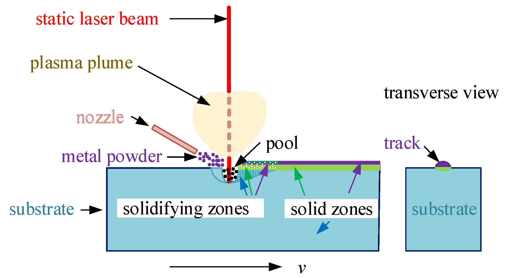
:1. Introduction
- Choosing an appropriate powder material for the given application;
- Achieving the required coating quality;
- The accuracy of individual patterns;
- Problems with the discretization of the examined area, where the coated substrate continuously changes its phase and geometry;
- The inclusion of various stochastic phenomena (not all powder material is used during the process, the defocusing of the laser beam, and the reduction in its power due to plasma plume formation above the irradiated area);
- The significant amount of time (usually many hours) needed for the computation of one variant of the task.
2. Mathematical Model
2.1. Temperature Field
2.2. Field of Flow
2.3. Field of Mechanical Stresses
2.4. Numerical Solution
- The area matrix itself is mathematically much easier and faster to work with than the deformed geometry;
- It is possible to define an arbitrary shape of the spot of the pattern, therefore it is possible that the final shape of the deposited track will be closer to the real shape;
- The mesh is always generated without problems and faster using such a geometry, which also reduces the overall simulation computation time;
- Any overlapping of the deposited tracks can be performed;
- The amount of material deposited can be easily calculated;
- It can be found that the height of the track is also dependent on the welding speed and the flow rate of the powder.
3. Illustrative Example
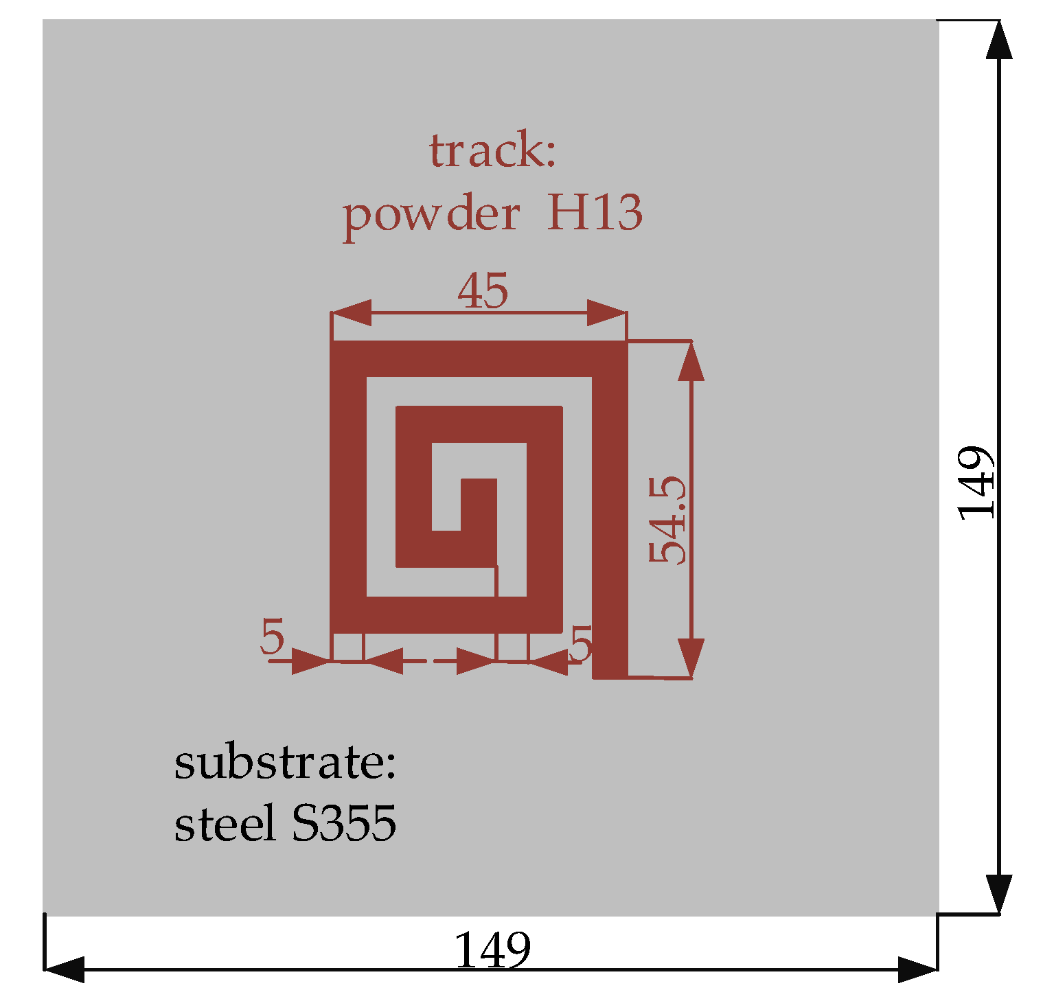
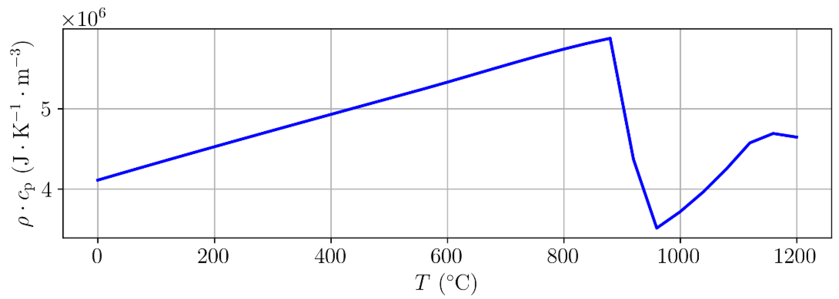
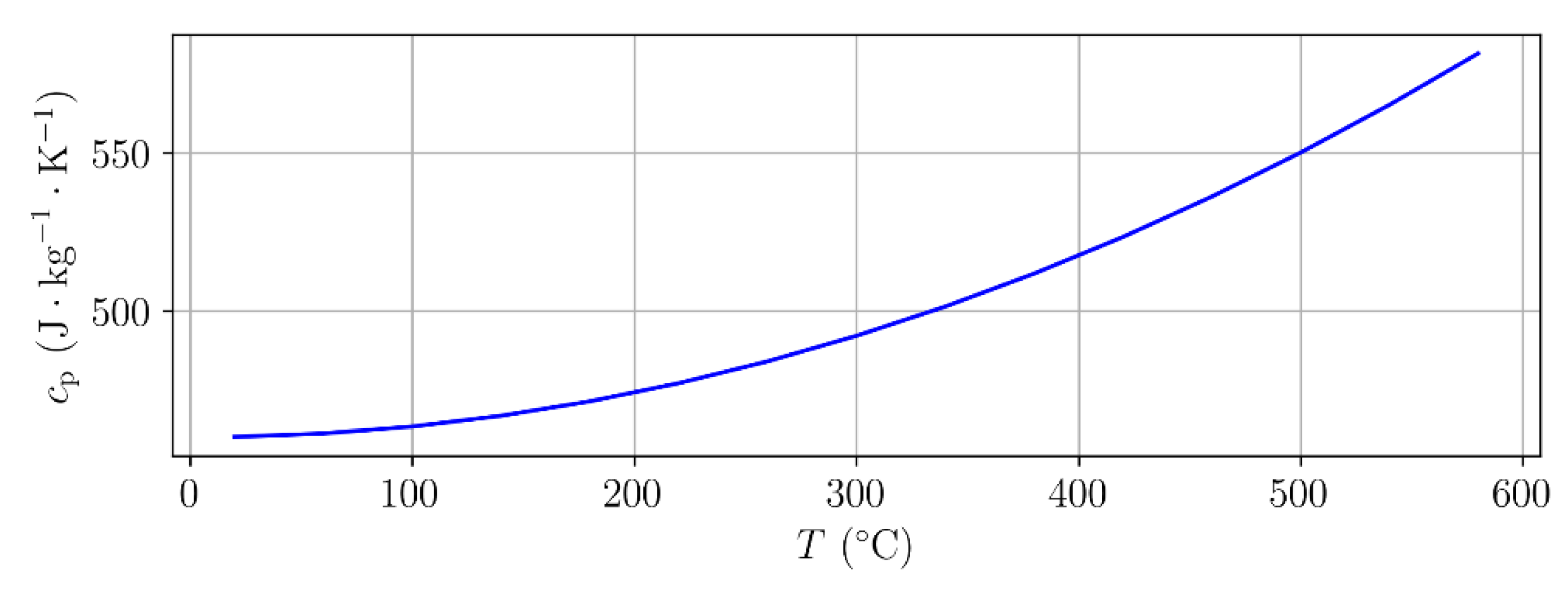
3.1. Input Data
3.2. Computations
3.3. Experiment
4. Conclusions
Author Contributions
Funding
Data Availability Statement
Conflicts of Interest
References
- von Starck, A.; Mühlbauer, A.; Kramer, C. Handbook of Thermoprocessing Technologies: Fundamentals, Processes, Components, Safety; Vulkan: Essen, Germany, 2005. [Google Scholar]
- Toyserkani, E.; Khajepour, A.; Corbin, S.F. Laser Cladding, 1st ed.; CRC Press: Boca Raton, FL, USA, 2005. [Google Scholar]
- Liu, J.; Yu, H.; Chen, C.; Weng, F.; Dai, J. Research and Development Status of Laser Cladding on Magnesium Alloys: A Review. Opt. Lasers Eng. 2015, 93, 195–210. [Google Scholar] [CrossRef]
- Zhong, M.; Liu, W. Laser surface cladding: The state of the art and challenges. Proc. Inst. Mech. Eng. Part C J. Mech. Eng. Sci. 2010, 224, 1041–1060. [Google Scholar] [CrossRef]
- Birger, E.M.; Moskvitin, G.V.; Polyakov, A.N.; Arkhipov, V.E. Industrial laser cladding: Current state and future. Weld. Int. 2011, 25, 234–243. [Google Scholar] [CrossRef]
- Lu, P.; Lewis, S.R.; Fretwell-Smith, S.; Engelberg, D.L.; Fletcher, D.I.; Lewis, R. Laser Cladding of Rail: The Effects of Depositing Material on Lower Rail Grades. Wear 2019, 438–439. [Google Scholar] [CrossRef]
- Zhang, H.; Pan, Y.; He, Y.; Jiao, H. Microstructure and properties of 6FeNiCoSiCrAlTi high-entropy alloy coating prepared by laser cladding. Appl. Surf. Sci. 2011, 257, 2259–2263. [Google Scholar] [CrossRef]
- Vilar, R.; Santos, E.C.; Ferreira, P.N.; Franco, N.; da Silva, R.C. Structure of NiCrAlY coatings deposited on single-crystal alloy turbine blade material by laser cladding. Acta Mater. 2009, 57, 5292–5302. [Google Scholar] [CrossRef]
- Yi, P.; Liu, Y.; Fan, C.; Zhan, X.; Xu, P.; Liu, T. Impact analysis of the thermal mechanical coupling characteristics of graphite morphologies during laser cladding of gray cast iron. Opt. Laser Technol. 2017, 90, 52–64. [Google Scholar]
- Javid, Y.; Ghoreishi, M. Thermo-mechanical analysis in pulsed laser cladding of WC powder on Inconel 718. Int. J. Adv. Manuf. Technol. 2017, 92, 69–79. [Google Scholar] [CrossRef]
- Zhang, Z.; Farahmand, P.; Kovacevic, R. Laser cladding of 420 stainless steel with molybdenum on mild steel A36 by a high power direct diode laser. Mater. Des. 2016, 109, 686–699. [Google Scholar] [CrossRef] [Green Version]
- Wen, S.; Shin, Y. Modeling of transport phenomena during the coaxial laser direct deposition process. J. Appl. Phys. 2010, 108, 044908. [Google Scholar]
- Kovaleva, I.; Kovalev, O.; Zaitsev, A.; Smurov, I. Numerical Simulation and Comparison of Powder Jet Profiles for Different Types of Coaxial Nozzles in Direct Material Deposition. Phys. Procedia 2013, 41, 870–872. [Google Scholar] [CrossRef] [Green Version]
- Yang, N. Concentration model based on movement model of powder flow in coaxial laser cladding. Opt. Laser Technol. 2009, 41, 94–98. [Google Scholar] [CrossRef]
- Huang, Y.; Khamesee, M.B.; Toyserkani, E. A Comprehensive Analytical Model for Laser Powder-fed Additive Manufacturing. Addit. Manuf. 2016, 12, 90–99. [Google Scholar] [CrossRef]
- Lee, Y.; Farson, D.F. Simulation of transport phenomena and melt pool shape for multiple layer additive manufacturing. J. Laser Appl. 2016, 28, 012006. [Google Scholar]
- Li, C.; Liu, C.; Li, S.; Zhang, Z.; Zeng, M.; Wang, F.; Wang, J.; Guo, Y. Numerical Simulation of Thermal Evolution and Solidification Behavior of Laser Cladding AlSiTiNi Composite Coatings. Coatings 2019, 9, 391. [Google Scholar] [CrossRef] [Green Version]
- Ghorashi, M.S.; Farrahi, G.H.; Movahhedy, M.R. Considering Cyclic Plasticity to Predict Residual Stresses in Laser Cladding of Inconel 718 Multi Bead Samples. J. Manuf. Processes 2019, 42, 149–158. [Google Scholar] [CrossRef]
- Nazemi, N.; Urbanic, J. An Experimental and Simulation Study for Powder Injection Multitrack Laser Cladding of P420 Stainless Steel on AISI 1018 Steel for Selected Mechanical Properties. J. Manuf. Sci. Eng. 2017, 140, 011009. [Google Scholar]
- Diez, M.; Campana, E.F.; Stern, F. Design-space Dimensionality Reduction in Shape Optimization by Karhunen–Loève Expansion. Comput. Methods Appl. Mech. Eng. 2015, 283, 1525–1544. [Google Scholar] [CrossRef]
- Solin, P.; Segeth, K.; Dolezel, I. Higher-Order Finite Element Methods; Chapman and Hall/CRC: Boca Raton, FL, USA, 2003. [Google Scholar]
- Ibarra-Medina, J.; Vogel, M.; Pinkerton, A.J. A CFD Model of Laser Cladding: From Deposition Head to Melt Pool Dynamics. In Proceedings of the Proc. ICALEO 2011, Orlando, FL, USA, 23–27 October 2011. [Google Scholar]
- Holman, J.P. Heat Transfer; McGraw-Hill: New York, NY, USA, 2009. [Google Scholar]
- Panek, D.; Kotlan, V.; Hamar, R.; Dolezel, I. Novel Algorithm for Modeling Combined Laser and Induction Welding Respecting Keyhole Effect. Appl. Math. Comput. 2018, 319, 254–263. [Google Scholar] [CrossRef]
- Courtois, M.; Carin, M.; le Mason, P.; Gaied, S.; Balabane, M. A Complete Model of Keyhole and Melt Pool Dynamics to Analyze Instabilities and Collapse during Laser Welding. J. Laser Appl. 2014, 26, 042001. [Google Scholar] [CrossRef] [Green Version]
- Tan, C.; Zhao, L.; Chen, M.; Cheng, J.; Wu, C.; Liu, Q.; Yang, H.; Yin, Z.; Liao, W. Experimental and theoretical investigation of localized CO2 laser interaction with fused silica during the process of surface damage mitigation. Results Phys. 2020, 16, 102936. [Google Scholar]
- Xu, J.; Luo, Y.; Zhu, L.; Han, J.; Zhang, C.; Chen, D. Effect of shielding gas on the plasma plume in pulsed laser welding. Measurement 2018, 134, 25–32. [Google Scholar]
- Zhang, Z.; Kovacevic, R. A thermo-mechanical model for simulating the temperature and stress distribution during laser cladding process. Int. J. Adv. Manuf. Technol. 2019, 102, 457–472. [Google Scholar] [CrossRef]
- Elmesalamy, A.S.; Abdolvand, H.; Walsh, J.N.; Francis, J.A.; Suder, W.; Williams, S.; Li, L. Measurement and modelling of the residual stresses in autogenous and narrow gap laser welded AISI grade 316L stainless steel plates. Int. J. Press. Vessel. Pip. 2016, 147, 64–78. [Google Scholar] [CrossRef] [Green Version]
- Zhu, J.; Khurshid, M.; Barsoum, Z. Accuracy of computational welding mechanics methods for estimation of angular distortion and residual stresses. Weld. World 2019, 63, 1391–1405. [Google Scholar]
- Dzioba, I.; Lipiec, S. Fracture Mechanisms of S355 Steel—Experimental Research, FEM Simulation and SEM Observation. Materials 2019, 12, 23. [Google Scholar] [CrossRef] [PubMed] [Green Version]
- Narvan, M.; Al-Rubaie, K.S.; Elbestawi, M. Process-Structure-Property Relationships of AISI H13 Tool Steel Processed with Selective Laser Melting. Materials 2019, 12, 2284. [Google Scholar] [CrossRef] [PubMed] [Green Version]
- Gunasegaram, D.R.; Murphy, A.B.; Barnard, A.; DebRoy, T.; Mathews, M.J.; Ladani, L.; Gu, D. Towards Developing Multiscale-Multiphysics Models and their Surrogates for Digital Twins of Metal Additive Manufacturing. Addit. Manuf. 2021, 46, 102089. [Google Scholar]


Publisher’s Note: MDPI stays neutral with regard to jurisdictional claims in published maps and institutional affiliations. |
© 2021 by the authors. Licensee MDPI, Basel, Switzerland. This article is an open access article distributed under the terms and conditions of the Creative Commons Attribution (CC BY) license (https://creativecommons.org/licenses/by/4.0/).
Share and Cite
Doležel, I.; Kotlan, V.; Hamar, R.; Slobodník, K. Modelling the Laser Cladding of Geometrically More Complex Tracks and Its Experimental Verification. Metals 2021, 11, 1403. https://doi.org/10.3390/met11091403
Doležel I, Kotlan V, Hamar R, Slobodník K. Modelling the Laser Cladding of Geometrically More Complex Tracks and Its Experimental Verification. Metals. 2021; 11(9):1403. https://doi.org/10.3390/met11091403
Chicago/Turabian StyleDoležel, Ivo, Václav Kotlan, Roman Hamar, and Karel Slobodník. 2021. "Modelling the Laser Cladding of Geometrically More Complex Tracks and Its Experimental Verification" Metals 11, no. 9: 1403. https://doi.org/10.3390/met11091403
APA StyleDoležel, I., Kotlan, V., Hamar, R., & Slobodník, K. (2021). Modelling the Laser Cladding of Geometrically More Complex Tracks and Its Experimental Verification. Metals, 11(9), 1403. https://doi.org/10.3390/met11091403